MCU-Based Solar Powered Chicken Feeder
Elenor M. Reyes1 , Arnold D. Arellano2, John Paolo B. Dela Vega3, Joriel R. Jimenez4 , Rupert John C. Quindong5
College of Engineering, Architecture and Fine Arts, Batangas State University, Alangilan, Batangas City, Philippines
1
[email protected], [email protected], 3
[email protected], [email protected], 5
Date Received: November 9, 2015; Date Revised: December 19, 2015
Asia Pacific Journal of Multidisciplinary Research
Vol. 3 No.5, 111-118 December 2015 Part II P-ISSN 2350-7756 E-ISSN 2350-8442 www.apjmr.com
Abstract - Poultry is a great potential industry particularly in Batangas Province. The method of feeding chicken needs to be considered as chicken must be fed regularly to be more productive. The conventional method of feeding chicken is the need to continuously provide the food, be alert and conscious on the food remaining in cages and to feed the chickens in a correct period of time to avoid the decline of the production. Growers also find it difficult to manage their businesses effectively because they need to be around the cages every now and then to monitor the poultry. Timing and exactness are the key to provide a uniform time in feeding the chickens. This will benefit the owner of the business in terms of time and effort. Another advantage of this project is in terms of savings to the owner of the poultry business.
This technology was designed to automatically feed chickens at a given period of time and to give alarm when the feeds are running out of supply. The power to be supplied to this prototype will be drawn from the sun by means of solar panels and will be stored in typical car battery. The feeds will be stored in a container and evenly distributed by using a conveyor to the feeding basin of the poultry. It will be more efficient than manual conventional way of feeding because less effort will be needed in feeding the chickens and less feeds will be wasted. In addition to that, the stored power can also be used for lighting purposes for the growers to save energy and energy bills.
Keywords - Chicken Feeder, Microcontrollers, Solar energy, Smart Relays, Poultry farming
INTRODUCTION
Electricity is the most used energy nowadays. Most of the equipment and gadgets used by people need electrical energy to provide comfort and to make their life simpler and easier. There are different sources of energy that can be converted or transferred to electrical energy like energies from sun, water, wind, and even from mechanical movement. Energy from these sources can be converted to electrical energy by means of windmills for wind energy, water turbines for hydro-energy, and solar panels for solar energy. These forms of renewable energy have a great contribution to power or energy consumption.
One of the applications of electricity is the automation of different equipment which can have a large role in making life easy. Automation is the use of machines, control systems and information technologies to optimize productivity in the production of goods and delivery of services
and more reliable with its service. Automation has entered many fields, in production, manufacturing and
even in some simple gadgets used in people’s daily
life. One of the fields that automation has entered is agricultural business.
Agriculture is facing a challenge as well as an opportunity as doubling food production in four to five decades is needed due to population growth. Greater investment is vital to ensure agricultural development, especially in funding international research institutions designed to promote development [2].Indeed, from a world perspective, we already are in crisis with one person out of seven starving [3]. But in the Philippines, the livestock subsector which shared 18.45 percent in total agricultural production grew by 3.25 percent in the recent year [4].Philippines, being an agriculture-dependent country, uses automation to improve agricultural output.
such as hog, cattle and poultry. Among these is a great potential industry because of its production efficiency. In Batangas Province, there are poultry businesses with at least 500 chickens in one building of cages. In this type of business, the method of feeding chicken needs to be considered as chickens must be fed regularly at a desired period of time to be more productive.
According to Amogbai[5], before the development of the automatic feeder technology, people were used to the conventional method of feeding chicken which is by filling containers with grains and feeds manually. In this method, owner of the business must be alert and conscious on the food remaining in cages and feed the chickens in a correct period of time to avoid the decline of production. The sufficient amount of the food provided also cannot be determined clearly. It is such a waste and non-economical.
Poultry growers also find it difficult to manage their businesses effectively because they need to be around the cages every now and then to monitor the poultry [6]. Timing and exactness are the keys to provide chickens what they need and to be more productive. The advantage of the automated feeder is in terms of savings to the owner of the poultry business who would have more precise and accurate method of feeding.
Nowadays, there are feeding systems available in the market but they cannot be used by small scale poultry entrepreneurs because the automatic feeder is suitable more for commercial purpose and would not be applicable for them. The feeding system in the market needs high investment for equipment and devices. Second, more workspace is needed to put and assemble the automatic system. The system would be installed in front of the cages, therefore consuming lot of space in the structure.
According to poultry raisers, to maintain healthy chickens, fresh feeds should be kept at all times. The amount of feeds at the feeders should be enough in order to avoid waste. Therefore, this automatic chicken feeder system will provide the food efficiency
and also chicken’s feeding time. The controller system provides an efficient solution for exact quantity of the food distribution, fixed feeding time and hassle free automatic feeding in order to help breeders. User
could set desired time and save it to microcontroller’s
memory[6].
OBJECTIVES OF THE STUDY
The design project primarily aimed to design and develop a MCU- Based Solar Powered Chicken Feeder. Specifically, the study aimed to evaluate the existing Automatic Chicken Feeder in terms of Design, Construction, and Operation; determine the
project’s design considerations and requirements as to Philippine Electrical Code (PEC) and National Electrical Manufacturer’s Association (NEMA); to prepare the project’s design plan and specifications: General Description of the Project; Construction Layouts; Design Computation and Analysis; Circuit Diagrams; and Program and its Implementation; to determine the methods of fabrication and assembly; to test the performance as to its efficiency, time response, maintenance and current drain: Procedure and Results and discussions.
MATERIALS AND METHODS
In conducting the study, the researchers used engineering and planning type of research which involved the use of plans, procedures and strategies to come up with the working prototype.
The Internet greatly helped the researchers gather additional information and ideas for the study. They started the design as they analyzed and took into considerations published theories, ideas and facts about the solar power generation and automatic chicken feeding and how it works. Conceptual literature and related studies were considered in the construction of the proposed project. By reviewing some of the related literature, the researchers identified the problem of the study to avoid any mistakes and to improve the research design and instrumentation plan.
Moreover, the study took into consideration the requirement and standards of the PEC, IEEE, NEMA and the knowledge of the existing technology to be modified to come up with the design of the MCU-based solar-powered chicken feeder.
RESULTS AND DISCUSSION
1.1Evaluation of the existing chicken feeder. The existing automatic chicken feeder allows the dispensing of feeds in time using motor- and actuator-controlled microcontroller. The feed dispenser uses pneumatic cylinder which is powered by 220V AC. The actuator opens and closes the feeds dispenser at desired time to feed the flocks as set in the microcontroller.
1.1.1 Design. The automatic feeder has a feed bin that was designed to hold feeds capacity of 60kg that will dispense feeds, during specified time, in pans. There are approximately 40 pans each building with a distance of 90 cm from each other. A PIC 40 pin type microcontroller was used to automatically actuate the 220-230V, 0.5MPa pneumatic cylinder through 220V AC source. Moreover, the 0.75kW, 3.5A stepper motor convey the pans assembly to catch the dispensed power feeds. 1.1.2 Construction. The feeds dispenser is made up of aluminum materials and is located at the center of the existing automatic feeder. The forty (40) circular pans of 360mm diameter each was attached to a placed 90 cm away from each other. The stepper motor is located in line with the pans connected by galvanized steel pipes.
1.1.3 Operation. The main operation of the existing feeder is to maintain the schedule for chicken feeding in a specific time with the exact and sufficient amount of feeds. The system is operated according to the time that has been set in the microcontroller. Powering on the system, the LCD will initialize. User can set the time needed to feed the chicken and will run for 24 hours. Once the system detected the time given, the microcontroller sets ON the motor to dispense feeds. The amount of feeds depends on the delay set in the software.
The design of the existing chicken feeder is supplied by a 220V AC source. Its construction is for the bulk number of flocks in a single cage only. It maintains the schedule for chicken feeding in a specific time. It helps people to feed the chicken with exact and sufficient amount and operates according to the time set. Breeders then do not have to worry if they forget to feed the chicken or if they want to leave the chicken for a few days.
1.2 Design Considerations and Requirements Some provisions of the following standards were cited and considered as guides for the development
and operation of a MCU based Solar Powered Chicken Feeder.
1.2.1 Philippine Electrical Code (PEC).
PEC provides standard for the following areas: Solar Photovoltaic Systems – Installation. In Article 6.90.1.4 (b), photovoltaic source circuits and photovoltaic output circuits shall not be contained in the same raceway, cable tray, cable, outlet box, junction box, or similar fitting as feeders or branch circuits of other systems, unless the conductors of the different systems are separated by a partition or are connected together[7].
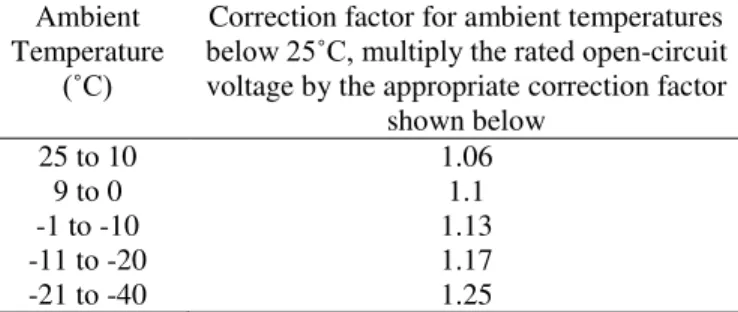
According to Article 6.90.2.1 (a), In a dc photovoltaic source circuit or output circuit, the maximum system voltage for that circuit shall be computed as the sum of the rated open-circuit voltage of the series-connected photovoltaic modules corrected for the lowest expected ambient temperature. For crystalline and multi-crystalline silicon modules, the rated open circuit shall be multiplied be the correction factor provided in Table 1. This voltage shall be used to determine the voltage rating of cables, disconnects, over current devices, and other equipment. Where the lowest expected ambient temperature is below -40 ˚C, or where other than crystalline or multi-crystalline silicon photovoltaic modules are used, the system voltage adjustment shall be made in accordance with the manufacturer’s instructions.
Moreover Article 6.90.4.1 (b), stated that types SE, UF, USE and USE-2 single conductor cable shall be permitted in photovoltaic source circuit where installed in the same manner as a type UF multi-conductor cable in accordance with Art. 3.39. Where exposed to direct rays of the sun, type UF cable identified as sunlight-resistant or type USE cable shall be used.
Table 1. Voltage Correction Factors for silicon Crystalline and Modules Multi-Crystalline
Ambient Temperature
(˚C)
Correction factor for ambient temperatures
below 25˚C, multiply the rated open-circuit voltage by the appropriate correction factor
shown below 25 to 10 1.06
As gleaned Art. 6.90.4.1 (a), all raceway and cable wiring methods included in this code and other wiring systems and fittings especially intended and identified for use on photovoltaic arrays shall be permitted. Where wiring devices with integral enclosures are used, sufficient length of cable shall be provided to facilitate replacement.
Art. 6.90.4.1 (d), mandates that single conductor cables listed for outdoor use that are sunlight-resistant and moisture-resistant with sizes 1.25mm2(1.25mm dia.) and 0.75mm2 (1.0mm dia.) shall be permitted for modules interconnections where such cables met the ampacity requirements of Circuit Sizing and Current (Art 6.90.2.2) shall be used to determine the cable ampacity and temperature derating factors.
Article 6.90.4.4, junction, pull, and outlet boxes located behind modules or panels shall be installed so that the wiring contained in them can be rendered accessible directly or by displacement as a module(s) or panel(s) secured by a removable fasteners and connected by a flexible wiring systems.
According to Art. 6.90.8.2 (a), equipment shall be provided to control the charging process of the battery. Charge control shall not be required where the design of the photovoltaic source circuit is matched to voltage rating and charge current requirements of the interconnected battery cells, and the maximum charging current multiplied by 1 hour is less than 3 percent of the rated battery capacity expressed in ampere-hours or as recommended by the battery manufacturers
All adjusting means for control of the charging process shall be accessible only to licensed electrical practitioner or non-licensed electrical practitioner under the supervision of the licensed electrical practitioner.
Art. 6.90.8.4 states that flexible cables, as identified in Article 4.0, in sizes 60mm2 and larger shall be permitted within the battery enclosure from battery terminals to nearby junction box where they shall be connected to an approved wiring method. Flexible battery cables shall also be permitted between batteries and cells within the battery enclosure. Such cables shall be listed for hard service use and identified as moisture-resistant.
1.2.2 National Electrical Manufacturer’s Association (NEMA)
The NEMA standard was referred for the proper selection of motors and contactors.
Selection and use of Single-Phase Motor.NEMA MG 11-1977, Section 4.4, provides that the most important consideration in selecting a motor of the appropriate type is to obtain a motor that will perform satisfactorily for the application involved. Universal motors are used where high speeds are required, where increasing the speed of induction motors is not feasible, or when varying speeds are desired[8].
Universal Motors.NEMA MG 1-2003, Section 1.2, states that a universal motor is a series-wound type motor designed to operate at approximately the same speed and output on either direct-current or single phase alternating current of a frequency not greater than 60 Hz and approximately the same rms voltage.
Contactors. NEMA ICS 7.1, Section 2.6.1 Where a definite-purpose contactor is used in conjunction with gate interlocking, the contactor shall be capable of interrupting current up to the maximum current limit setting at maximum voltage at least once, independent of the gate interlocking.
Conductor Size.NEMA ICS 7.1, Section 2.8.2, states that conductors for panel wiring shall be no smaller than No. 18 AWG and those for electronic and solid state control subassemblies no smaller than No. 30 AWG.
1.3 Design Plans and Specifications
Figure 1.1 MCU Based Solar Powered Chicken Feeder
1.3.2 Construction Layouts. The MCU based Solar Powered Chicken Feeder prototype is made up of three main parts: the solar power source, the conveyor set and auxiliaries. The solar power source consists of the solar panel and the battery. However, the conveyor set has the motor, motor speed controller and the conveyor itself. The added auxiliary compositions are aluminum container, charge controller, inverter, solenoid and the smart relay.
The perspective view of the project is shown in Figure 1.2. Along with it is the component’s dimensions.
Figure 1.2 Perspective View
The 300W solar panel is connected to the battery by means of the charge controller. The controller is inside the panel box along with other auxiliaries. The auxiliaries are wired and connected inside the panel box. The overall length of the conveyor is 2.5m with a 0.7m height. The width of the conveyor is 0.16m which is applicable for feeding the chicken.
1.3.3Circuit diagram. The circuit diagram of the project and the connection of all components of
project is shown in figure 4.5. It composes of Solar panel, charge controller, microcontroller, solenoid valve and the conveyor motor.
Figure 1.3 Circuit Diagram
Figure 1.3 shows the circuit diagram of the project study. As gleaned from the diagram, the solar panel is connected to the charge controller and to the battery then connected to the inverter that supplies power to the smart relay which controls the conveyor motor and solenoid.
1.3.4 Program and its implementations.
The automatic chicken feeder uses a smart relay. This smart relay is an MCU based relay which also needs a program to be installed to function on desired time and desired sequence.
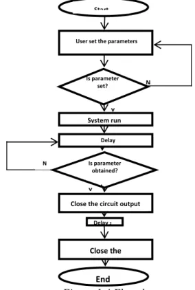
Figure 1.4 Flowchart
N Start
User set the parameters
Is parameter set?
System run
Delay
Is parameter obtained?
Close the circuit output
Delay 2
Close the
End Y
N
1.3.4.1 Flow Chart
Flowchart shows the main sequence of the program that is installed in the smart relay. Figure 1.4 shows the flowchart of the program.
In the flowchart, the sequence is to first set together with the parameters. As the parameters is set, the system will run. When the system meets the parameters with the set program. The system will stop and open the loop on the output part of the program.
1.3.4.2 Implementation. The program installed in the Smart Relay(MCU based) lets the user to set the desired time of feeding. The main circuit is supplied with 220V AC which serves as switch to its input and output. The parameters that can be changed are the clock in the program, the desired time of switching that can be set at a maximum of three times a day and the duration of which the program is running.
1.4. Testing Methodologies
The MCU Based Solar Powered Chicken Feeder was evaluated and analyzed to test its performance. Three tests were performed for the
project’s efficiency and calibration. These were (a)
Performance Test (Feeding Test) (b) Break-In Test and (c)Current Drain.
1.4.1 Performance Test. The test includes two sets and three trials each having different setting time. Each setting time had its corresponding time response. This time response would determine the efficiency of the project. To get the efficiency of the project in terms of exactness of feeding, the proponents divided the setting time by its corresponding time response. This is represented by the equation:
%eff = � � � � �
� � � � x 100
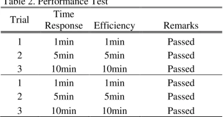
Table 2. Performance Test
Trial Time
Response Efficiency Remarks
1 1min 1min Passed
2 5min 5min Passed
3 10min 10min Passed
1 1min 1min Passed
2 5min 5min Passed
3 10min 10min Passed
Table 2 contains the test results of the model’s performance upon setting it to perform its task on a 1min,5mins and 10mins basis. Three trials were made in each specified time. As the time arrived on the set time, the conveyor started its operation with the duration set by the proponents to last. And in the second time set by the proponents, the conveyor also operates at its desired output. This means that the model worked on the desired output which is set by the proponents. This also indicated efficiency of the project as it responded exactly on the time set to it.
1.4.2 Break-In Test. This test was conducted to identify equipment problems, diagnose equipment problems or to confirm that repair measures were effective in the project. Maintenance test was done within the range of time that the proponents set. Three trials on 48hrs, three trials on 72hrs and three trials on 96hrs. If after these tests were done, and no problems occur, then the project passed the said test.
Table 3. Break-In Test
Trial Time Remarks
1 48 Passed
2 48 Passed
3 48 Passed
1 72 Passed
2 72 Passed
3 72 Passed
1 96 Passed
2 96 Passed
3 96 Passed
This was done within the range of time that proponents set. Three trials on 48hrs, three trials on 72hrs and three trials in 96hrs. After the maintenance test, Table 3 shows the results in the test done. It was concluded that the model functioned as the proponents desired. This means that along the operations, the model did not encountered any problems in different equipment used.
connected to the load and its discharging rate limits were measured.
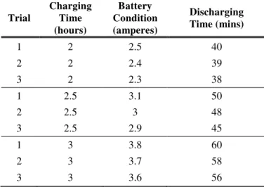
Table 4. Current Drain (Load : 50 watt motor and Internal resistance)
Trial
Charging Time (hours)
Battery Condition (amperes)
Discharging Time (mins)
1 2 2.5 40
2 2 2.4 39
3 2 2.3 38
1 2.5 3.1 50
2 2.5 3 48
3 2.5 2.9 45
1 3 3.8 60
2 3 3.7 58
3 3 3.6 56
This was done within the range of time that proponents set. Three trials on 2hrs, three trials on 2.5hrs and three trials in 3hrs. Table 4 shows the results in the test done. Results revealed that the prototype drained current ranging from 38-60 mins. This means that as the charging time becomes longer, the discharging time of the battery connected to the load also becomes longer.
CONCLUSIONS
1. The existing automatic chicken feeder feeds chicken confined in one cage only. This automatic feeder operates in the ground which feed dispenser is rotating around the cage.
2. The completed study complies with the design requirement stated in the Philippine Electrical Code (PEC) in terms of size of wire, the solar panel and the storage batteries; the National Electrical Manufacturers Association (NEMA) in terms of electrical motors; the IEEE on the provisions on the sizing of batteries and the IEC standards and provisions in association with the electrical wires and the photovoltaic device up to the programmable devices.
3. The preparation of the project’s electrical plan
and specifications are of great significance in lessening the errors in fabricating the completed project. Selecting the right parts of the feeder is considered for more efficient output.
4. Smart relays are more reliable and user friendly in terms of programs related to time control.
5. The methods and processes are easily followed in making the prototype. Knowing the right tools and preparing them at hand before the fabrication, lessened the time in assembling the device.
6. Since the operation of the chicken feeder is not continuous, the discharging time of the battery becomes longer that it will not require having a backup supply. And as the charging time becomes longer, the discharging time also lasts longer. Also, the chicken feeder is an efficient project as it responds exactly to the time set by the user.
RECOMMENDATIONS
Based from the findings and conclusions, the following recommendations are suggested:
1.In order to complete the operation in a farm, the researchers recommend including in the automation system the water consumption of the chicken.
2.Since the size of the motor used in the conveyor system is proportional to the length of the conveyor, it is recommended to replace the motor rating.
3.To avoid the rapid consumption of the feeds when the feeding operation began to operate, a barrier must be equipped in front of the chicken cages and should be remove automatically after the operation of the conveyor.
4.Since the automated chicken feeder was only applied to a single row of chicken cages, application of the smart relay should be functional to all layers of the cages.
5.Size of the feeds container should be proportional to the number of cages covered by the automatic chicken feeder.
6.In order to increase the efficiency of the conveyor system, more rollers must be equipped.
REFERENCES
[1] Drishti Kanjilal, Divyata Singh, Rakhi Reddy, Prof Jimmy Mathew (2014). Smart Farm: Extending Automation to the Farm Level, International Journal of Scientific & Technology Research Volume 3, Issue 7, 109 – 113
[2] Ryan, John, Norwood, Colin and Diekmann, Juergen (2012). Features of an Experimental Station at an International Agricultural Research Center that Enhance Regional Impact. Sustainable Agriculture Research; Vol. 1, No. 2 (Aug 2012), 88-99
[4] Performance of Philippine Agriculture: retrieved from http://agstat.psa.gov.ph
[5] Amogbai, V.I. (2013), Development of a Mechanical Family Poultry Feeder, Journal of Emerging Trends in Engineering and Applied Sciences (JETEAS) 4(6): 837-846
[6] Zain, A. (2008), Automatic Chicken Feeder System Using Microcontroller, Asian Journal of Agriculture and Development, Vol. 2, Nos. 1 & 2
[7] Philippine Electrical Code Part I Volume I, Institute of Integrated Electrical Engineers of the Phils.,Inc., Philippines, 2009
[8] ANSI/NEMA MG 1: Motors and Generators: retrieved from www.nema.org
Copyrights