Original article (full paper)
A robot for verifying the precision of total
reaction time measurement
Tânia Brusque Crocetta
Santa Catarina State University, Florianópolis, SC, Brazil
Tiago Kroich
Federal University of Santa Catarina, Florianópolis, SC, Brazil
Argeu Carlos Thiesen Lucas Borges Noé Gomes Borges Júnior
Santa Catarina State University, Florianópolis, SC, Brazil
Luiz Carlos de Abreu
School of Medicine of ABC, Santo André, SP, Brazil
Alexandro Andrade
Santa Catarina State University, Florianópolis, SC, Brazil
Abstract—The level of variability in psychomotor behavior and the use of several distinct sets of equipments in Reaction Time (RT) assessments might jeopardize the validity and reliability of such measures. This study presents the
develop-ment and veriication of Emboici Robot—a robot capable of performing accurate RT assessments consisting of response to a visual stimulus by pressing a button—whose purpose is to measure the accuracy of RT assessments. We evaluated the accuracy and precision on four different days, each providing 300 measurements. These assessments generated a RT of 46.95ms (+6.04). No signiicant effects were found in the RTs obtained and, as a result, there is evidence that the
Emboici Robot is stable, reliable, and precise. The robot can be a viable solution for verifying precision and accuracy of any given software with simple RT assessments with visual stimulus requiring as response the pressing of a button or key.
Keywords: movement sciences, robotics, software, innovation
Resumo—“Um robô para veriicar a precisão da medição do tempo de reação total.” A variabilidade do comportamento psicomotor e o uso de diferentes equipamentos para medidas de Tempo de Reação (TR) podem comprometer a vali
-dade e idedigni-dade destas medidas. Este estudo desenvolve e valida o Emboici Robot—um robô capaz de responder
a estímulos visuais com o pressionamento de um botão—para medir a precisão e acurácia das medidas de TR visual. Avaliou-se as medidas de TR em quatro ocasiões, com 300 medidas em cada uma. Estas medidas geraram um TR de
46,95ms (+6,04). Não foram encontradas diferenças signiicativas nos TRs obtidos pelo Emboici Robot, e os resultados demonstram evidências de que o Emboici Robot é estável, idedigno e preciso para a obtenção de medidas de TR, po
-dendo ser uma solução viável para veriicar a precisão e acurácia de qualquer software com testes de TR simples com estímulo visual que requeira o pressionamento de um botão ou tecla para a resposta.
Palavras chave: ciências do movimento, robótica, software, inovação
Resumen—“Un robot de veriicar la precisión de la medición del tiempo total de reacción.” La variabilidad de comportamiento psicomotor y el uso de diferentes equipos para medidas de tiempo de reacción (TR) pueden poner en peligro la validez y iabilidad de estas medidas. Este estudio desarrolla y valida Emboici Robot—capaz de responder con precisión a los estímulos visuales
con sólo pulsar un botón—para medir la precisión y la exactitud de las medidas de TR visuales. Se evaluaron las medidas de
TR en cuatro ocasiones, con 300 pasos cada uno. Estas medidas generaron un TR de 46,95ms (+6,04). No se encontraron
dife-rencias signiicativas en los TR obtenidos por Emboici Robot. Los resultados mostraron que Emboici robot es estable, coniable y preciso para la obtención de mediciones de TR, y puede ser una solución viable para veriicar la exactitud y la precisión de
cualquier software con pruebas de TR con estímulo visual simple que requieren presionar un botón o clave para la respuesta.
Introduction
Reaction Time (RT) is a simple measure of the time elapsed in milliseconds between the receiving of a stimulus and the
onset of a motor response to it (Erickson et al., 2011). This is
currently used by modern psychology as a signiicant method
of diagnosis (Zajdel & Nowak, 2007). When we apply a test to measure RT using computer software, we can record the time elapsed between the receiving of a stimulus and the conclusion
of a task—this is named Total Reaction Time (TRT).
Since computers are normally associated with precision and certainty—not to mention the possibility of introducing more complex stimuli (Spruyt, Clarysse, Vansteenwegen, Baeyens, & Hermans, 2010)—it is expected that the improvement and availability of platforms used in cognitive computerized testing platforms (such as the RT assessments) allow the application of monitoring tests, producing precise measures and speed of processing (Coppel, 2011).
Many researchers have examined the precision in RT as-sessments by computer systems (Ohyanagi & Sengoku, 2010).
This is a major concern of studies on RT testing, chiely using computers not speciically designed to manage time with milli -second precision (Myors, 1998) or those requiring additional hardware for the task (Xie, Yang, Yang, & He, 2005).
It is clear that video monitors, the devices used in responding to stimuli, the computers’ operational systems, and the software
used in presenting the stimuli are technical factors that inluence
precision (Ohyanagi & Sengoku, 2010).
The obstacles faced when using Windows Operational System and computer devices (monitor, keyboard, and mouse) were widely discussed in previous literature (Beaumont, 1981, 1982, 1985a, 1985b; Cernich, Brennana, Barker, & Bleiberg, 2007; Lincoln & Lane, 1980; Plant, Hammond, & Turner, 2004; Plant, Hammond, & Whitehouse, 2002, 2003; Plant & Turner,
2009; Stoet, 2010), with signiicant delays when using one or
other device, or even between different manufacturers of the same device.
On account of these setbacks, it may be that data obtained from one computer should not be strictly compared with data from another (Segalowitz & Graves, 1990), or that one test performed in a study with a certain mouse might produce
sig-niicantly different results in another using a different mouse
(Plant et al., 2003). Hence, it poses a problem for establishing valid, accurate measures.
In order to attain more legitimate and trustworthy results with RT tests, some researchers seek to access time regardless
of the operational system time (Eichstaedt, 2001) through low
-level programming languages (Xie et al., 2005), measuring time with a secondary computer, separate from the one assessing RT (De Clercq, Crombez, Buysse, & Roeyers, 2003), developing software that guarantees precision of time (Deary, Liewald, & Nissan, 2011; Forster & Forster, 2003), and, more recently, in-troducing external devices managed by microprocessors (Neath,
Earle, Hallett, & Surprenant, 2011; Ohyanagi & Sengoku, 2010).
There is commercial software that uses external
accesso-ries for recording responses—such as the “Response Panel”
in the Vienna Test System (Schuhfried & Prieler, 2005), or the
SR-BOX (Serial Response Box) in the E-Prime® (Cavézian et al., 2010)—in order to eliminate the delays already known to be present in the use of mouse devices (Cernich et al., 2007; Chambers & Brown, 2003) or keyboards (Damian, 2010; Neath
et al., 2011).
The dificulty of comparing the results obtained from the
performance of RT tests in one given system and another
(chiely due to the variability of human beings) calls for a
common, consistent element that is accurate and precise, such as a robot, so that these different systems might be matched and analyzed.
Easy-to-use, low-cost sensors with integrated open source
boards such as Arduino are being used with reasonable results in studies, e.g. as further encouragement for paraplegic patients to move their limbs (Rush & Acm, 2009), aiding in the daily recovery of patients (Bin Ambar, Bin Mhd Poad, Bin Mohd Ali, Bin Ahmad, & Mahadi bin Abdul Jamil, 2012), or even
working in a system that classiies different sorts of lights for
the blind (Ando, 2005).
A study by D’ausilio (2012) demonstrated the accuracy and precision of an Arduino microcontroller board—which ensures portability and precision entirely independent of the computer or external software—for typical experiments with psychological and neurophysiological assessments requiring proper control over time and input/output signals. The rese-archer performs eight different assessments with common input/output evaluation in order to show which operations might lessen precision.
There is also an increasing interest in operations involving the interaction between humans and robots in the areas of medicine, housekeeping, manufacturing, and entertainment (Dongjun, Irene, Yong-Lae, Oussama, & Mark, 2010).
With these inquiries in mind and considering both the variability of psychomotor behavior and the use of different
measuring equipment for RT that might compromise the eficacy
of such measures, the present study presents the formulation,
development, and veriication of a solution: the Emboici Robot, a robot built from low-cost components to perform accurate Total Reaction Time assessments consisting of the response to a visual stimulus by pressing a button or key.
Presenting the Emboici Robot
The Emboici Robot (whose name is a reference to the arms of a praying mantis, known in Tupy language as “Emboici”)
was developed with the intent of measuring the Total Reac-tion Time (TRT) in millisecond precision (see Figure 1). In searching for a solution to the validation of precision in TRT measurements by software, we reasoned that there must be a solution outside the computer where the software is being used and which could provide less possible variability while still being affordable.
This device also allows data acquisition with no signiicant
deviation, making it possible to monitor the measurement of any given software with visual TRT in different computer hardware
and stability in measurements made by the software as well as the variation to which the software is prone when used in computers with different hardware.
The monitoring of stimulus alteration is performed by a microprocessor through the use of a light-sensitive photodiode with the same color spectrum as the human eye—370nm (violet) to 750nm (red) (Cassares & Petrella, 2001). The photodiode sends an electric signal representing the color intensity, which
in turn is codiied into a digital signal by the microprocessor. The microprocessor identiies the expected color and activates
a digital servo (with a metal shaft bolted to a propeller) to the point of pressing the button or key, and then turning to its ori-ginal position and awaiting the next stimulus.
A box was made using Medium-density iberboard (MDF)
to hold the Arduino board and the protoboard (see Figure 1-B), while a second MDF box contained the digital servo (see Figure 1-A), providing support for the metal shaft used in pressing the button or key. These components were assembled in separate
boxes for the sake of lexibility. In this way, adjustments can
be made to suit different keyboards, buttons, etc.
The diagram illustrating the electronic components inside the Emboici Robot—an Arduino board, a digital servo, and a photodiode—is shown in Figure 2. Besides these components,
six resistors were used, as well as a BC548 ampliier, three keys for coniguring the robot, and three light-emitting diodes (LED)
in the colors red, white, and green.
The robot was assembled with an open source Arduino UNO, a BPW21 photodiode for identifying color alteration in the visual stimulus, and a metal shaft triggered by a digital servo (SC-1267SG), detailed as follows:
Arduino UNO. An Arduino board is an open source
electro-nic prototyping platform based on lexibility, with easy-to-use
hardware and software (Arduino, 2012; D’Ausilio, 2012), de-signed to promote physical interaction between computer and environment. For this purpose, it utilizes electronic devices in a simple way, based on free software and hardware (Cavalcante, Tavolaro, & Molisani, 2011).
We connected the Arduino board to a 5 Volt commercial
AC-DC power supply. Every sensor was connected to the Arduino
board so that it recognized the voltage in the analog signal. The analog signal was then forwarded to the 10 bit analog-to-digital converter (ADC) for data processing (Bin Ambar et al., 2012).
Photodiode (BPW21). We used silicon BPW21 photodiode in order to discern light alteration within the visual stimulus. It was positioned in a hermetically sealed casing with a built-in glass, adequate for color correction and ideal for adjusting the total light exposure (Ando, 2005).
This photodiode (BPW21) is tuned to the sensitivity of the human eye (Vλ) and thus distinguishes between the visible spectrum of 370nm (violet) up to 750nm (red) (Cassares & Petrella, 2001).
Digital servo (SC-1267SG). We used a SC-1267SG Digital Servo manufactured by Savöx. Digital servos are a special kind of direct current motors designed to rotate their axes in a 180-degree arc (Bingol & Aydogan, 2012). The precision achie-ved with these motors is considered good and is obtained by measuring the width of incoming pulses and the period between these pulses (Dias, Grehs, Mendes, Moura, & Ferrugem, 2011). The digital servo is powered by a 5V supply, provided here by the Arduino board.
Arduino programming. The Arduino is programmed in C/
C++ using an IDE (Integrated Development Environment) of its own. This IDE—which is available on Windows and Linux—
allows the program to be uploaded to Arduino. The software
written for the Arduino is called “sketches” and is saved with the ile extension .ino (Arduino, 2012). The ATmega 328 chip
assembled in the Arduino handles the program and interacts with the peripherals (Bin Ambar et al., 2012).
Method
The present study presents the formulation, development, and evaluation of a robot (the Emboici Robot) built with low-cost components. The Emboici Robot was designed as a solution to measure accurately Total Reaction Time (TRT) assessments consisting of the response to a visual stimulus by pressing a button or key.
The color alteration in the visual stimulus is monitored by a microprocessor through the use of a photodiode. This
photodiode identiies the previously-designated color and
triggers the digital servo, which in turn triggers the propel-ler to rotate the metal shaft up to the point where it presses the response key or button, and then returns to its original position.
For the Emboici Robot to perform a TRT assessment, sof-tware or another device was needed to generate the stimulus and measure the response time. In the present study, we opted to use another device to generate a stimulus and to measure the response time with as little variability as possible in terms of hardware and software used. To this end, we assembled a device
named “TRT Simulator”—also using an Arduino board—as
described below.
TRT simulator (TRTsim) including an Arduino board
We opted to assemble a device whose purpose is to simulate a
TRT assessment by lighting a green light-emitting diode (LED),
the response to which consists of pressing an on/off button.
Since this value stood for the total amount of time
elapsed between the stimulus (stimulus-LED) and the
pressing of the response key (SR-key), we also measured the time between the Emboici Robot’s sensor perceiving the stimulus and the time precisely prior to the triggering of the digital servo.
In order to achieve this, we altered the Emboici Robot’s
source code so that the red LED is lit before issuing the trigge -ring command to the digital servo. One channel is linked to the
cable triggering the light of the stimulus-LED in the TRTsim
and another channel is linked to the cable triggering the red
LED in the Emboici Robot. Through this coniguration we can
measure the TRTsim and Emboici Robot response time before the digital servo is triggered (therefore bypassing the mechanical
components). The time measured falls below 1ms, or 248.0 μs
(see Figure 3-B)
Making use of these measures, we were able to overlook the time spent by the Arduino board and the photodiode, considering the time measured by the TRTsim as the same as measured by the Emboici Robot.
Procedure
The irst step was to identify the time spent by the TRT
Simulator (TRTsim) to record the TRT assessments obtained by the Emboici Robot, through the use of a Tektronix TDS 1002 60MHz 1GS/s oscilloscope. By measuring the time elapsed between the pressing of the SR-key and the fading
of the green LED (stimulus-LED), we could determine the
TRTsim’s precision. One channel from the oscilloscope was connected to the SR-key’s power supply and another to the
stimulus-LED’s power supply, making sure that this measure
was under 1ms.
Figure 3. Measurements obtained by the oscilloscope during tests made by the Emboici Robot. In (A): a TRT assessment by the Emboici Robot—
with channel 1 (CH1) connected to the stimulus-LED and channel 2 (CH2) connected to the stimulus response key (SR-key)—resulting in 47ms. And in (B): a measurement of the time elapsed between the activation of the stimulus-LED and the triggering command sent to the digital servo, amounting to less than 1ms (=248 μs)—after which we can infer that the time recorded with the Emboici Robot is due to the mechanical process through which the digital servo moves to press the SR-key.
The TRT Simulator (TRTsim) consists of an Arduino board
with a white LED (to aid in monitoring the functioning and preparation of the TRTsim), a green LED (the stimulus remains
on until the on/off key is pressed), an on/off switch (to record the response to the stimulus), and a HanRun HR911105A 10/49 network adapter (to recover the response time recorded by the TRTsim). The Arduino microcontroller was programmed to
trigger the green LED at random times, thus generating the
visual stimulus the Emboici Robot expects. Stimulus response consists of pressing the on/off key (SR-key).
For studies that require stimulus control with millisecond
precision, the use of LEDs might be a satisfying solution, since the effort needed to conigure a tiny LED lamp is minimal
(Stoet, 2010). In this way, the Arduino microprocessor’s delay
in μs can be discarded without compromising the recorded
measurement by the TRTsim.
A WebService was set up in order to receive TRT data taken by the TRTsim only after the completion of TRT measures, so that the transmission time presents no interference in the TRT recording by the microcontroller.
With this TRT Simulator we have a stimulus generator with inaccuracy of less than 1 millisecond, enabling us to analyze the precision with which the Emboici Robot can operate.
Verifying the execution time of the TRT Simulator
For the veriication of time as recorded by the TRT (TRT -sim), we used the Tektronix TDS 1002 60MHz 1GS/s oscillos-cope, with one channel connected to the cable triggering the
green LED (stimulus-LED) and the other connected to the cable
After we were certain the time spent by the TRTsim would not compromise the TRT assessments made by the Emboici Robot (under 1ms), we began gathering the TRT assessments.
These tests were performed on the 1st, 5th, 7th, and 8th day
(interleaved to ensure uniformity and avoid fatigue) of the same month. On each of these days 300 assessments were made,
amounting to 1.200 TRT assessments. Each day the Emboici Robot was used, we redid the robot’s setup in the way described below.
There were stops at every 100 TRT assessments made, when the TRTsim would stop the stimulus signaling and wait until the results were transferred. This transfer was carried out through the TRTsim’s network adapter. In a computer with network access, we could connect to the WebService address http://10.14.0.111, which in turn was available only when the
TRTsim entered on-hold/transfer mode (white LED turned on). The 100 assessments were then stored in TXT iles for
later evaluation.
TRT assessment
The TRTsim worked this way: the green LED (stimulus-LED) was lit and the on/off switch (SR-key) was pressed. The
time elapsed between the stimulus and its response was
identi-ied as the total reaction time (TRT). The TRT assessments were
stored in the TRT Simulator and uploaded for later evaluation.
Emboici Robot settings
We can see in Figure 4-B the primary control keys for the
Emboici Robot: the armKey (1) used in setting up and moni-toring the robot arm’s position in relation to the SR-key; the
colorKey (2) which conigures stimulus color; and the startEn
-dKey (3) used in initiating and inishing a set of tests.
Each of these keys was designed to ine-tune one of the Emboici Robot’s functions. Their settings are described below.
Setting up the arm’s position for pressing the on/off switch (armKey)
For the digital servo to press the response key (SR-key) we
had to conigure the correct position of the Emboici Robot’s
“arm” (the metal shaft attached to the digital servo). Pressing
the armKey made the arm rotate 1 degree clockwise (step = 1º). The armKey was pressed once more when the arm came to
the point of pressing the SR-key, so that the inal position was
stored in the Emboici Robot’s memory.
Figure 4.Presenting the robot and TRT Simulator used in this study. The Emboici Robot in two MDF boxes, A+B, containing an Arduino board, a photodiode sensitive to color alteration, and a digital servo with a metal shaft attached for pressing the on/off switch (SR-key); C+D = TRT Simulator, which consists of an Arduino board, a network adapter, an on/off switch, and an LED for signaling the stimulus. The Emboici Robot contains three control keys: the startEndKey used in initiating and inishing a set of tests; the colorKey for designating the color of the stimulus
The robot arm was connected manually to the bearing gear at approximately 180º (horizontal) in relation to the table
surface. Then the armKey was pressed once and the red LED
lit up signaling that the arm rotated 1 step clockwise (1º = one degree) at a time until the armKey was pressed again.
Once the SR-key was completely pressed we pressed the
armKey to indicate its inal position (thus ensuring that the
SR-key would be pressed in the TRT assessments). Then, the
red LED was turned off and the arm rotated 3º (three degrees)
counterclockwise, to what is the initial position for all.
Setting up the stimulus color (colorKey) shown to the photodiode
In order for the photodiode to identify the stimulus alteration, the
stimulus color had to be conigured (the color chosen in this study
was the green). The photodiode connected to the Emboici Robot was
positioned above the stimulus-LED. When we pressed the colorKey
the color then showing was stored in the Emboici Robot’s memory. In this study we attached the photodiode to the
stimulus-LED with electrical tape, enclosing the TRTsim’s green stimulus-LED
(see Figure 4-C).
Subsequently, the TRTsim was turned on to light up the
stimulus-LED (green LED turned on = stimulus-LED). The
colorKey was pressed once (the Emboici Robot’s green LED then lit up) and the digital value of the stimulus-LED color was stored (that is to say, the digital value of the stimulus-LED’s green color was stored). To inish adjusting the color settings
we had to press the colorKey once again (the Emboici Robot’s
green LED was then turned off).
The Emboici Robot was then started. Every time the sti
-mulus-LED was lit and identiied by the photodiode, the robot
arm was triggered.
The start/end monitoring key (startEndKey)
For the Emboici Robot to start testing, the startEndKey had to be pressed once. Right after this, the red and green LEDs
were lit and the arm pressed the SR-key, then returned to wait
for the startEndKey to be pressed again. The TRT Simulator
was ready to initiate a set of tests.
When the startEndKey was pressed for the second time, the red and green LEDs went out and the white LED lit up, indica
-ting that the photodiode was wai-ting for the predeined stimulus.
Data analysis
Descriptive statistics were used to characterize the time per-formance of robot, and Friedman’s test, Intra Class Correlation
coeficient and Bland Altman tests to infer the reliability of the
robot.
Results
A total of 1200 total reaction time (TRT) assessments were performed by the Emboici Robot over four interspersed days (1st,
5th, 7th, and 8th days of the same month). On each day 300 TRT
performance measurements were taken. The test was generated
and controlled by a “TRT Simulator” (TRTsim) built for the sake
of measuring the time elapsed between the activation of the
stimulus-LED and the pressing of the on/off switch (SR-key).
Descriptive statistics regarding the TRT obtained by the Em-boici Robot in each of the four sets of tests are shown in Table 1; such measures were taken in order to evaluate the reliability of the Emboici Robot detailed in this study. At every 100 TRT assessments performed the data were uploaded to a WebService by means of a network adapter. Before and after each set of 100 tests the TRTsim was also rebooted.
There was no signiicant change in the TRT results obtained
in the four days of testing, reporting the time elapsed between
identifying the stimulus (green stimulus-LED) and the response
(pressing the TRTsim’s SR-key) to be an overall average of 46.95ms (SD, 6.04). As we can observe in Table 1, little variation
occurred between sets of tests. The average TRT luctuated 0.29
from the lowest mean (46.71ms 5th day) to the highest mean
(47.00ms 1st day). The standard deviation was also relatively
Day 1 Day 5 Day 7 Day 8 All days
Occurrences 300 300 300 300 1200
Average 47.00 46.71 46.95 46.92 46.95
Standard deviation 5.84 6.05 6.01 6.25 6.04
Mode (frequency - %) 42 (20 – 6.7)
46 (20 – 6.7) 42 (27 – 9.0) 41 (20 – 6.7) 43 (20 – 6.7) 42 (72 – 6.0)
Skewness 0.115 0.164 0.144 0.132 0.136
Range 26 24 26 24 27
Minimum (frequency) 35 (1) 35 (1) 34 (1) 35 (1) 34 (1)
Maximum (frequency) 61 (1) 59 (1) 60 (1) 59 (2) 61 (1)
1st Quartile 42.00 42.00 42.00 41.25 42.00
2nd Quartile 47.00 46.00 46.00 46.00 46.00
3rd Quartile 52.00 52.00 52.00 53.00 52.00
Note: The measures were stored in a TRT simulator built with an Arduino board and an on/off switch for recording the stimulus response. This stimulus consisted
of turning on a green LED prompting the Emboici Robot’s photodiode. The robot then reacted by using its arm to press the stimulus response key.
low, ranging from 5.84ms to 6.25ms—a difference amounting to 0.41ms. Skewness ranged from 0.115 to 0.164, and the standard deviation for asymmetry (0.141) was the same for all samples.
Application of Friedman’s test shows that there are not statistically significant changes in the distribution of TRTs
measurement over the four days, χ2=3.360, df = 3, p = .339.
The alpha coefficient for the four items is .855, suggesting that the items have relatively high internal consistency.
The ICC for single measures is much lower at 0.544 than the reliability for all the performance averaged together which is at
0.855 (95% conidence interval = 0.826-0.880) (average measures).
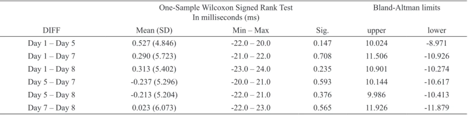
Using the Bland and Altman that discuss the option of using confidence interval bounds, based on the standard error of the mean, for the upper and lower reference lines, and could verify if the two methods are comparable, then differences should be small, with the mean of the differen-ces close to 0 (Table 2). The spread of performance on the day 1 is comparable to the spread on the day 5 (and so far all others combined days). The limits of agreement plotted do fit better, although some skewness remains (Figure 5).
The data collected show that the TRT assessments obtained with the Emboici Robot average the duration of 46.92ms. There
is no signiicant deviation between the samples collected.
Discussion
One thousand and two hundred total reaction time (TRT) assessments were collected by a TRT simulator and performed by a robot named Emboici Robot. This robot was designed to react to a stimulus by pressing a button or key. The measure-ments were obtained over the period of four different days to ensure that the Emboici Robot was stable.
The present study made use not only of computer software but also of an external accessory (the TRT Simulator) to generate and collect stimulus. We could verify the simulator’s accuracy and reliability by monitoring it with a precise oscilloscope. Some studies evaluated the precision in RT assessments made by computer software through the use of external devices; such research, however, typically used the same computer for genera-ting and/or measuring time (De Clercq et al., 2003; McKinney, MacCormac, & Welsh-Bohmer, 1999).
A study by Neath et al. (2011) proposed assembling a device consisting of a photodetector used in identifying changes in brightness on a monitor. This then triggered a solenoid, which in turn pressed the keyboard. The device was used to simulate RT assessments in three different software systems, on two distinct
keyboards and two different iMac hardware speciications. As
a result, a difference of 5-10ms was found. Using open-source Arduino microcontroller boards Schubert, D’Ausilio, and Canto (2013) demonstrated the reliability, robustness, and precision
of this communication in six studies conirmed that the error
added to the measurement had an SD of less than 1 ms (Schubert, D’Ausilio, & Canto, 2013).
In the present study, the TRT simulator generates the stimu-lus, calculates the TRT, and stores the results. This simulator is an autonomous system, composed of its own high-performance microprocessor consisting of no circuit other than its own.
Accordingly, the Emboici Robot is another autonomous circuit, powered by a 5V power supply which—as shown in the study of Neath et al. (2011)—was capable of identifying alteration in light stimulus and trigger a digital servo to press a response key.
Analysis of agreement produced by the Bland-Altman’s test showed that variability between the combined days is near zero and revealed that measurements obtained by tests meet the expected agreement by each day.
The Emboici Robot can be suitable not only for users with technical expertise, but also those with limited budget, because of its accessible, low-cost components. The Arduino board is a relatively inexpensive option (D’Ausilio, 2012), costing less than a hundred Reais (approximately 45 dollars as of April, 2014). Furthermore, the whole set of components used in as-sembling the Emboici Robot did not exceed the value of 200 Reais (approximately 90 dollars as of April, 2014).
Researchers in the area of sport psychology and motor behavior show great interest in the performance of reaction time (RT) tests, either among athletes (Hung, Spalding, Santa
Maria, & Hatield, 2004) or in studies examining the inluence
of sport and physical exercise on athletes and non-athletes (Chan, Wong, Liu, Yu, & Yan, 2011). As Kornspan (2007) notes,
one of the irst studies to investigate the psychological aspects
of sport in a psychology lab in 1894 used RT tests on fencers (Kornspan, 2007).
One-Sample Wilcoxon Signed Rank Test In milliseconds (ms)
Bland-Altman limits
DIFF Mean (SD) Min – Max Sig. upper lower
Day 1 – Day 5 0.527 (4.846) -22.0 – 20.0 0.147 10.024 -8.971
Day 1 – Day 7 0.290 (5.723) -21.0 – 22.0 0.708 11.506 -10.926
Day 1 – Day 8 0.313 (5.402) -23.0 – 24.0 0.235 10.901 -10.274
Day 5 – Day 7 -0.237 (5.296) -20.0 – 21.0 0.593 10.144 -10.617
Day 5 – Day 8 -0.213 (5.204) -22.0 – 21.0 0.376 9.986 -10.413
Day 7 – Day 8 0.023 (6.073) -22.0 – 23.0 0.565 11.926 -11.879 Table 2. Test of whether DIFF has a median of 0 with the One-Sample Wilcoxon Test procedure includes the mean and standard deviation of DIFF,
Minimum and Maximum values and the signiicance level for the test that the median of DIFF equals 0.
Given the importance of studies making use of RT tests and the variability of RT results obtained by different sets of software and hardware, it is highly recommended that researchers using
a computer to collect RT measurements irst evaluate the preci -sion and reliability of the chosen platform (Neath et al., 2011). In short, our study shows evidence that the Emboici Robot
is a trustworthy and precise technical resource, capable of properly evaluating tests based on computer software which require responding to a stimulus by quickly and accurately pressing a button or key.
Conclusion
In this study, a robot named Emboici Robot was developed, evaluated, and equipped with a system capable of monitoring color alteration in the visual stimulus generated by a total reac-tion time (TRT) test. The robot described consists of an Arduino board, a metal shaft attached to a digital servo, and a photodiode capable of monitoring real-time color changes in the visual sti-mulus. The system we propose is easily assembled and requires only low-cost components. The TRT measurements generated enable the researcher—through the use of the Emboici Robot, whose variability proved to be stable—to evaluate properly any TRT software that makes use of a simple visual TRT test.
Researchers may use this system (Emboici Robot), with these low-cost interfaces, to validate the measurements made by a set of hardware and software in RT tests. Future studies will focus on evaluating some previously consolidated RT software and hardware, aiming to improve software that requires precision in the measurement of time.
Making use of the robot to simulate TRT tests may pinpoint issues in the development of software, as well as identify the
most adequate coniguration to be used. This serves not only to
validate a given software, but also to verify other consolidated software currently in use.
References
Ando, B. (2005, 16-19 May 2005). An Environmental Sensor Providing
Home Light Classiication to Blind People. Paper presented at the Instrumentation and Measurement Technology Conference, 2005.
IMTC 2005. Proceedings of the IEEE.
Arduino. (2012). Arduino Main Site. Retrieved jun., 2012, from http://arduino.cc/en/
Beaumont, J. G. (1981). Microcomputer-aided assessment using standard psychometric procedures. Behavior Research Methods & Instrumentation, 13, 430-433. doi: 10.3758/bf03202050
Beaumont, J.G. (1982). System requirements for interactive testing. International Journal of Man-Machine Studies, 17, 311-320. doi: 10.1016/s0020-7373(82)80033-3
Beaumont, J.G. (1985a). Speed of response using keyboard and screen -based microcomputer response media. International Journal of Man -Machine Studies, 23, 61-70. doi: 10.1016/s0020-7373(85)80024-9 Beaumont, J.G. (1985b). The effect of microcomputer presentation
and response medium on digit span performance. International Journal of Man-Machine Studies, 22, 11-18. doi: 10.1016/s0020-7373(85)80074-2
Bin Ambar, R., Bin Mhd Poad, H., Bin Mohd Ali, A.M., Bin Ahmad, M.S., & Mahadi bin Abdul Jamil, M. (2012, 27-28 Feb. 2012). Multi-sensor arm rehabilitation monitoring device. Paper
presen-ted at the Biomedical Engineering (ICoBE), 2012 International
Conference on.
Bingol, O., & Aydogan, O. (2012). Web Based Remote Controlled
Electrical Motor Laboratory used as Educational Tool. Przeglad Elektrotechniczny, 88, 342-346.
Cassares, N.C., & Petrella, Y.L.M.M. (2001). Inluência da radiação
de luz sobre acervos museológicos. Anais do Museu Paulista: História e Cultura Material, 8-9, 177-192.
Cavalcante, M.A., Tavolaro, C.R.C., & Molisani, E. (2011). Física com
Arduino para iniciantes. Rev. Bras. Ensino Fís., 33, 4503-4503. Retrieved from:
Cavézian, C., Gaudry, I., Perez, C., Coubard, O., Doucet, G., Peyrin,
C., . . . Chokron, S. (2010). Speciic impairments in visual pro -cessing following lesion side in hemianopic patients. Cortex, 46, 1123-1131. doi: 10.1016/j.cortex.2009.08.013
Cernich, A.N., Brennana, D.M., Barker, L.M., & Bleiberg, J. (2007). Sources of error in computerized neuropsychological assessment. Archives of Clinical Neuropsychology, 22, Supplement 1, 39-48. doi: 10.1016/j.acn.2006.10.004
Chambers, C.D., & Brown, M. (2003). Timing accuracy under Micro-soft Windows revealed through external chronometry. Behavior Research Methods Instruments & Computers, 35, 96-108. doi: 10.3758/bf03195501
Chan, J.S.Y., Wong, A.C.N., Liu, Y., Yu, J., & Yan, J.H. (2011).
Fencing expertise and physical itness enhance action inhibition. Psychology of Sport and Exercise, 12, 509-514. doi: 10.1016/j. psychsport.2011.04.006
Coppel, D.B. (2011). Use of Neuropsychological Evaluations. Physical Medicine and Rehabilitation Clinics of North America, 22, 653-+. doi: 10.1016/j.pmr.2011.08.006
D’Ausilio, A. (2012). Arduino: A low-cost multipurpose lab equip-ment. Behavior Research Methods, 44, 305-313. doi: 10.3758/ s13428-011-0163-z
Damian, M.F. (2010). Does variability in human performance ou-tweigh imprecision in response devices such as computer keybo-ards? Behavior Research Methods, 42, 205-211. doi: 10.3758/ brm.42.1.205
De Clercq, A., Crombez, G., Buysse, A., & Roeyers, H. (2003). A simple and sensitive method to measure timing accuracy. Behavior Research Methods Instruments & Computers, 35, 109-115. Deary, I.J., Liewald, D., & Nissan, J. (2011). A free, easy-to-use,
com-puter-based simple and four-choice reaction time programme: The Deary-Liewald reaction time task. Behavior Research Methods, 43, 258-268. doi: 10.3758/s13428-010-0024-1
Dias, M., Grehs, É., Mendes, S., Moura, S., & Ferrugem, A. (2011). Construção de um braço mecânico didático de baixo custo. Paper
presented at the XX Congresso de Iniciação Cientíica e III Mostra Cientíica, Pelotas - RS. www.ufpel.edu.br/cic/2011/anais/pdf/CE/ CE_00950.pdf
Dongjun, S., Irene, S., Yong-Lae, P., Oussama, K., & Mark, C. (2010). Design and Control of a Bio-inspired Human-friendly Robot. Int. J. Rob. Res., 29, 571-584. doi: 10.1177/0278364909353956
Eichstaedt, J. (2001). An inaccurate-timing ilter for reaction time
measurement by JAVA applets implementing Internet-based expe-riments. Behavior Research Methods Instruments & Computers, 33, 179-186. doi: 10.3758/bf03195364
Erickson, G.B., Citek, K., Cove, M., Wilczek, J., Linster, C., Bjarnason,
Forster, K., & Forster, J. (2003). DMDX: A Windows display program with millisecond accuracy. Behavior Research Methods, 35, 116-124. doi: 10.3758/BF03195503
Hung, T.M., Spalding, T.W., Santa Maria, D.L., & Hatield, B.D.
(2004). Assessment of reactive motor performance with even-t-related brain potentials: Attention processes in elite table tennis players. Journal of Sport & Exercise Psychology, 26, 317-337.
Kornspan, A.S. (2007). E.W. Scripture and the Yale psychology la -boratory: Studies related to athletes and physical activity. Sport Psychologist, 21, 152-169.
Lincoln, C.E., & Lane, D.M. (1980). Reaction-Time measurement
errors resulting from the use of CRT displays. Behavior Research Methods & Instrumentation, 12, 55-57. doi: 10.3758/bf03208326
McKinney, C.J., MacCormac, E.R., & Welsh-Bohmer, K.A. (1999).
Hardware and software for tachistoscopy: How to make accu-rate measurements on any PC utilizing the Microsoft Windows operating system. Behavior Research Methods Instruments & Computers, 31, 129-136. doi: 10.3758/bf03207703
Myors, B. (1998). A simple graphical technique for assessing timer accuracy of computer systems. Behavior Research Methods Ins-truments & Computers, 30, 454-456. doi: 10.3758/bf03200679
Neath, I., Earle, A., Hallett, D., & Surprenant, A.M. (2011). Response
time accuracy in Apple Macintosh computers. Behavior Research Methods, 43, 353-362. doi: 10.3758/s13428-011-0069-9
Ohyanagi, T., & Sengoku, Y. (2010). A solution for measuring accurate reaction time to visual stimuli realized with a programmable micro-controller. Behavior Research Methods, 42. doi: 10.3758/brm.42.1.242 Plant, R.R., Hammond, N., & Turner, G. (2004). Self-validating pre-sentation and response timing in cognitive paradigms: How and why? Behavior Research Methods Instruments & Computers, 36, 291-303. doi: 10.3758/bf03195575
Plant, R.R., Hammond, N., & Whitehouse, T. (2002). Toward an ex-perimental timing standards lab: Benchmarking precision in the real world. Behavior Research Methods Instruments & Computers, 34, 218-226. doi: 10.3758/bf03195446
Plant, R.R., Hammond, N., & Whitehouse, T. (2003). How choice of mouse may affect response timing in psychological studies. Beha-vior Research Methods Instruments & Computers, 35, 276-284. doi: 10.3758/bf03202553
Plant, R.R., & Turner, G. (2009). Millisecond precision psychological resear-ch in a world of commodity computers: New hardware, new problems? Behavior Research Methods, 41, 598-614. doi: 10.3758/brm.41.3.598 Rush, R.P., & Acm. (2009). Sensation Augmentation to Relieve Pres-sure Sore Formation in Wheelchair Users. Assets’09: Proceedings of the 11th International Acm Sigaccess Conference on Computers and Accessibility, 275-276.
Schubert, T., D’Ausilio, A., & Canto, R. (2013). Using Arduino micro-controller boards to measure response latencies. Behavior Research Methods, 45, 1332-1346. doi: 10.3758/s13428-013-0336-z Schuhfried, G., & Prieler, J. (2005). Manual Vienna Test System - Teste
de Reacções Simples e de Escolha [Vienna Test System Manual - Reaction Time]. Dr. G. Schuhfried Ges.m.b.H. Mödling.
Segalowitz, S.J., & Graves, R.E. (1990). Suitability of the IBM-XT, AT,
and PS/2 keyboard, mouse, and game port as response devices in reaction-time paradigms. Behavior Research Methods Instruments & Computers, 22, 283-289. doi: 10.3758/bf03209817
Spruyt, A., Clarysse, J., Vansteenwegen, D., Baeyens, F., & Hermans, D. (2010). Affect 4.0 A Free Software Package for Implementing
Psychological and Psychophysiological Experiments. Experimental Psychology, 57, 36-45. doi: 10.1027/1618-3169/a000005 Stoet, G. (2010). PsyToolkit: A software package for programming
psychological experiments using Linux. Behavior Research Me-thods, 42, 1096-1104. doi: 10.3758/brm.42.4.1096
Xie, S., Yang, Y., Yang, Z., & He, J. (2005). Millisecond-accurate synchronization of visual stimulus displays for cognitive research. Behav Res Methods, 37, 373-378.
Zajdel, R., & Nowak, D. (2007). Simple and complex reaction time measurement. A preliminary evaluation of new approach and diag-nostic tool. Computers in Biology and Medicine, 37, 1724-1730. doi: 10.1016/j.compbiomed.2007.04.008
Authors’ note
Tânia Brusque Crocetta ([email protected]) is afiliated with
the School of Medicine of ABC, Santo André, SP, Brazil; and also
afiliated with the Laboratory of Sport and Exercise Psychology, Cen -ter for Health Sciences and Sports, Santa Catarina State University, Florianópolis, SC, Brazil.
Alexandro Andrade ([email protected]) is a PhD, working with physical education, physical activity and health and sports psy-chology. He was Tânia Brusque Crocetta’s advisor on this project about reaction time, a topic under investigation in his laboratory for many years.
He is a full professor in the Department of Physical Education, and he
is advisor of master’s and doctoral degrees students at Santa Catarina State University, Florianópolis, SC, Brazil. Currently is a professor and researcher - PQ – CNPq. Dr. Andrade is coordinator of this project and
coordinator of the Laboratory of Sport and Exercise Psychology.
Luiz Carlos de Abreu ([email protected]) is afiliated with the School
of Medicine of ABC, Santo André, SP, Brazil.
Tiago Kroich ([email protected]) is afiliated with the Federal
University of Santa Catarina, Florianópolis, SC, Brazil.
Argeu Carlos Thiesen ([email protected]) and Lucas Borges ([email protected]) are computer Technicians in Center for Health Sciences and Sports, Santa Catarina State University, Florianópolis, SC, Brazil.
Noé Gomes Borges Júnior ([email protected]) is Laboratory of Instrumentation coordinator, Center for Health Sciences and Sports, Santa Catarina State University, Florianópolis, SC, Brazil.
Acknowledgments
Santa Catarina Pos-Graduate Program UNIEDU.
Corresponding author
Tânia Brusque Crocetta Santa Catarina State University
Rua Pascoal Simone, 358, Coqueiros, Florianópolis, SC 88080-350, Brazil Phone: +55 48 3321-8677
E-mail: [email protected]
Manuscript submitted on May 7, 2014 Manuscript accepted on October 27, 2014
Motriz. The Journal of Physical Education. UNESP. Rio Claro, SP, Brazil