Abstract
This work presents an investigation on wear prediction of multibody system including dry revolute clearance joint using a computational methodology. A procedure to analyze multibody system in which wear is present at revolute joints is presented. The study involves integrating a dynamics model of the mutibody system with clearance joint into a wear prediction procedure. The contact model in clearance joint is established using a hybrid nonlinear contact force model and the friction effect is considered by using a modified Coulomb friction model. The wear modeling of revolute clearance joint in multibody systems is presented based on the Archard’s wear model. Finally, an academic four-bar multibody mechanical system with revolute clearance joint is used as numerical example application to perform the investigation.
Keywords
Wear prediction; contact force; clearance joint; multibody dynamics; numerical simulation.
Wear prediction for dry revolute joint with clearance in multibody
system by integrating dynamics model and wear model
1 INTRODUCTION
Clearances in mechanism are unavoidable due to assemblage, manufacturing errors and wear. Clearance occurs in each active joint with the movement of mechanism. The movement of the real mechanisms is deflected from the ideal mechanism and the motion accuracy is decreased due to joint clearances. It is known that the performance of mechanisms is degraded by the presence of the clearance. These clearances modify the dynamic response of the system, justify the deviations between the numerical predictions and experimental measurements and eventually lead to important deviations between the projected performance of mechanisms and their real outcome (Bauchau and Rodriguez, 2012; Erkaya and Uzmay, 2010, 2012; Flores et al., 2004, 2006, 2010; Garcia, 2005; Schwab et al., 2012; Tian et al., 2009).
Over the last few decades, effects of clearance on dynamic responses of planar and spatial mechanisms using theoretical and experimental approaches have been studied by many researchers.
Z.F. Baia H.B. Zhangb Y. Sunc
aDepartment of Mechanical Engineering, Harbin Institute of Technology at Weihai, Weihai, 264209, Shandong, P.R. China bDepartment of Astronautic Engineering, Harbin Institute of Technology, Harbin 150001, Heilongjiang, P.R. China cDepartment of Astronautic Science and Mechanics, Harbin Institute of Technology, Harbin 150001, Heilongjiang, P.R. China
a
Corresponding author: [email protected]
Latin American Journal of Solids and Structures 11 (2014) 2624-2647
Stoenescu and Marghitu (2003) investigated the dynamic response of a planar, rigid-link mechanism with a sliding joint clearance and the response of the system with clearance was chaotic at relatively high crank speeds and low values of the coefficient of restitution. Bauchau and Ju (2006) focused on the development of methodologies for the analysis of unilateral contact conditions in joints with clearance and of the resulting normal and friction forces. Khemili and Romdhane (2008) investigated the dynamic behaviour of a planar flexible slider-crank mechanism having joint with clearance. And simulation and experimental tests were carried out for this goal. Bin and Ye (2008) presented a general methodology for dynamic characterization of the reheat-stop-valve mechanism with revolute clearance joints, in which the leading ingredients of the model proposed were the contact force model in consideration of the manufacturing tolerance and the thermal effects of the high temperature steam in working condition. Paulo Flores (2010) presented a parametric study on the dynamic response of planar multibody systems with multiple clearance joints. An elementary slider-crank mechanism was used to perform the parametric study. The main functional parameters were used for this study, namely, the diametric clearance size, the input crank speed and the number of joints modeled as clearance joints. Zhao and Bai (2011) studied the dynamics of a space robot manipulator with one joint clearance. The nonlinear equivalent spring-damper model is established for the contact model in joint clearance. Also, the friction effect is considered using the Coulomb friction model. Koshy (2013) presented a computational and experimental study on the contact forces developed in revolute clearance joints. A well-known slider-crank mechanism with a revolute clearance joint was used to perform the study. Muvengei (2013) studied the behavior of planar rigid-body mechanical systems due to the dynamic interaction of multiple revolute clearance joints. A slider-crank mechanism with two revolute joints with clearance is used as a demonstrative example. In conclusion, a great deal of researches on dynamic characteristics of mechanism with clearance are progressing and lots of productions are obtained, which have played a positive role in dynamic design, optimization analysis and performance improvement of mechanism with joint clearance.
However, there are less focuses on wear at joint with clearance in mltibody system. Most researches are based on the assumption of regular clearance model, which assumes that wear is not nonexistent in the joint, and the findings may be limited to the idealized case in which wear is not considered. This is contrary to a realistic situation in which wear is expected to increase the clearance size. The existence of clearances in kinematic joint causes the surface wear and incessant material loss of surface during the motion of joint elements, which increases the clearance size and changes the dynamic characteristics of mechanical system. The large amount works and models have been presented to show how wear in multibody systems is important over the last decades (Meng and. Ludema, 1995; Tasora et al., 2004; Mukras et al., 2010). In addition, in some mechanical systems, especially close-loop dynamic systems, wear in the joints significantly affects system dynamics, and the change in system dynamics greatly affects the wear progress.
Latin American Journal of Solids and Structures 11 (2014) 2624-2647
wear of the contacting surfaces can change the kinematics of the system as well as the contact pressure distribution, resulting in changes in future wear patterns.
The objective of this work is to study the wear phenomenon of dry revolute clearance joint in multibody systems based on the Archard’s wear model using a computational methodology. The wear prediction of clearance joint in multibody system is investigated by integrating the dynamics model of mutibody system with wear model. The main computational process for wear prediction of clearance joint includes two steps, which are dynamics analysis and wear analysis. The contact force model of revolute joint with clearance in multibody systems is established using a hybrid nonlinear continuous contact force model. And the friction effect is considered by using a modified Coulomb friction model. Finally, a four-bar multibody mechanical system is used as numerical example application to perform the investigation.
This paper is organized as follows. Section 2 establishes the dynamics model of multibody system with revolute clearance joint. Section 3 establishes the wear model in revolute clearance joint for multibody system. Section 4 presents the integration of the dynamics analysis and wear analysis. In section 5, a four-bar multibody mechanical system is used as numerical example application to perform the simulation and predict the wear of clearance joint in multibody system. Finally, section 6 ends the paper with the concluding remarks.
2 DYNAMICS MODELING OF MULTIBODY SYSTEM WITH REVOLUTE CLEARANCE JOINT
2.1 Definition of clearance
Joint clearance of mechanical system is necessary to allow the relative motion of connected bodies, as well as to permit the assemblage of the mechanical system. These clearances modify the dynamic response of the system and eventually lead to important deviations between the projected performance of mechanisms and their real outcome as well as unwanted shake responses and wear. In general, a clearance joint can be included in mechanism much like a revolute joint. The classical approach, known as zero-clearance approach, considers that the connecting points of two bodies linked by a revolute joint are coincident. The introduction of clearance in a joint separates these two points.
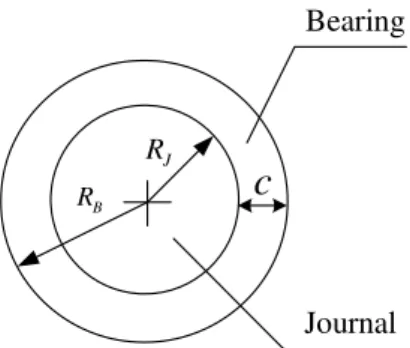
Figure 1 depicts a revolute joint with clearance. The difference in radii between the bearing and journal defines the size of radial clearance. Although, a revolute joint with clearance does not constrain any degree of freedom from the mechanical system like the ideal joint, it imposes some kinematic restrictions, limiting the journal to move within the bearing. Thus, when clearance is present in a revolute joint, two kinematic constraints are removed and two degrees of freedom are introduced instead. The dynamics of the joint are then controlled by forces working on the journal and bearing. Thus, whilst a perfect revolute joint in a mechanical system imposes kinematic constraints, a revolute clearance joint leads to force constraints. When contact exists between the journal and bearing, a contact force is applied perpendicular to the plane of collision.
Latin American Journal of Solids and Structures 11 (2014) 2624-2647
The radial clearance is defined as follow,
B J
c = R - R (1)
where RB and RJ are the radii of bearing and journal, respectively.
J
R
B
R
c
Bearing
Journal
Figure 1: Schematic representation of a revolute joint with clearance.
2.2 Mathematic model of revolute joint with clearance
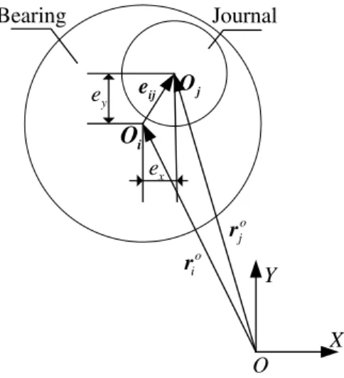
As shown in Figure 2, Oi and Oj define the centers of bearing and journal, respectively. rio and rjo are the vectors donating the positions of bearing and journal in the global inertia coordinate, respectively. Thus, in Figure 2, clearance vector is represented as Eq. (2):
o o
ij = j - i
e r r (2)
where eij represents the eccentric vector of journal relative to bearing. So the eccentricity of clearance vector can be represented as following:
2 2
ij = ex +ey
e (3)
The unit normal vector of bearing and journal at the point of their contact is represented as Eq. (4):
/eij ij
n = e (4)
That is
2 2
x y
e +e ij e
n = .
Figure 3 describes the collision between bearing and journal. Qi and Qj are the contact points on bearing and journal, respectively. Q
i
Latin American Journal of Solids and Structures 11 (2014) 2624-2647
ij
e c
d = - (5)
where c represents the radial clearance and it is a constant.
i
O
ij
e
Journal
j
O
X Y
O o i
r
o j
r
x e y e
Bearing
Figure 2: Clearance model in revolute joint of multibody system.
X i
O ij
e Journal
j
O
Y
Q i
r rjQ j
Q
i
Q
Bearing
Figure 3: Revolute joint clearance with contact.
Thus, d can be used to decide whether the bearing and journal have contacted. The kinematic contact condition between the bearing and journal can be given by Eq. (6):
2 2 0
x y
e e c
d= + - ³ . (6)
Latin American Journal of Solids and Structures 11 (2014) 2624-2647
the facet of contact, we can get the normal speed and tangential speed of the potential points of contact between the bearing and journal, as shown in Eq. (7):
( ( ) ) T T d d n t
v = n
v = t . (7)
where the unit tangential vector t can be achieved by reversing the unit normal vector n for 90.
2.3 Contact force model in revolute clearance joint 2.3.1 Normal contact force model
It is known that the performance of mechanisms is degraded by the presence of clearance due to the contact-impact forces. Contact and impact, such as it happens in a revolute clearance joint, is one of the most common types of dynamic loading conditions that give rise to impulsive forces, which in turn excite higher vibration modes and more severe wear of the mechanical systems. Thus, in this work, for a revolute joint with clearance, the contact between the journal and bearing is modeled using a hybrid nonlinear contact force model (Bai and Zhao, 2012):
mod n
n n
F =K d +D d (8)
where the elastic deformation force is represented by the first item of the right side of Eq. (8) and the energy losing is represented by the second item. d is the deformation, d is the relative deformation velocity. Kn is the nonlinear stiffness coefficient of the impact body and Dmod is the modified damping coefficient.
The nonlinear stiffness coefficient, Kn, is obtained from the following:
2 *
3
2 (3( ) 2 )
1
8 ( )
B J n B J R R K E R R d d p d - + =
- + (9)
where RB and RJ are radii of the bearing and journal, E* is compound elastic modulus and the expression is represented as:
2 2
*
1 1
1 i j
i j v v E E E
-= + (10)
where v and E are Poisson ratio and Young modulus, respectively.
The nonlinear stiffness coefficient, Kn, is related to the material property, geometry property, clearance size and deformation of contact bodies, and it varies with d and is not constant during the contact process.
Latin American Journal of Solids and Structures 11 (2014) 2624-2647
2(1 )
2
mod ( )
3 (1 )
4
e
c n
n e
K c e
D d
d
-= (11)
where ce is coefficient of restitution and d( )- is initial relative velocity of the impact point.
The above hybrid nonlinear continuous contact model was applied in dynamics analysis of mechanical systems with revolute clearance joint and the dynamics responses obtained with numerical models are compared with that of experimental results. It shows that the nonlinear continuous contact force model can effectively describe the dynamics response and contact forces of mechanism with clearance (Bai and Zhao, 2012)
2.3.2 Tangential Friction Force Model
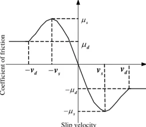
The tangential contact characteristic of clearance is represented using tangential friction force model. The most famous one is Coulomb friction model, which is used to represent the friction response in impact and contact process. In this paper, the friction effects in joints are considered as dry friction and a modified Coulomb friction model is used to represent the friction response between the journal and bearing. Friction coefficient, which is not a constant, is introduced in the modified Coulomb friction model. Friction coefficient is a function of tangential sliding velocity, which can represent the friction response in impact and contact process as well as the viscous and micro-slip phenomenon in relative low-velocity case more accurately. And also, the modified Coulomb friction model can avoid the case of abrupt change of friction in numerical calculation as the change of velocity direction.
The expression tangential friction force is shown as Eq. (12):
( ) t
t t n
t F = -mv F v
v (12)
where, friction coefficient m( )vt is a function of tangential sliding velocity and which can be expressed as:
2
( )
( ) ( ) 3 2 ( )
d t t d
t s t s
t d s d t s t d
d s d s
sign v v v
v v v v
v sign v v v v
v v v v
m
m m m m
m
- >
ì ü
ï æ - ö é æ - öùï
ï ç ÷ ç ÷ï
ï ç ÷ ê ç ÷úï
= -íï + - çç ÷÷÷ ê - çç ÷÷÷úýï £ £
-
-è ø ê è øú
ï ë ûï
ï ï î þ for for 2 2 3 2
t s t s
s s t s
s s
v v v v
v v v v m ìïï ïï ïï ïï ïïï íï ïï ïï
ï æ + ö æ + ö
ï ç ÷÷ ç ÷÷
ï - ç ÷ ç - ÷ <
ï çç ÷ çç ÷
ï è ø è ø
ïî for
(13)
Latin American Journal of Solids and Structures 11 (2014) 2624-2647
v
d
v
sv
sv
ds
d
s
d
Slip velocity
C
o
eff
icient of
friction
Figure 4: Coefficient of friction vs. slip velocity.
3 WEAR MODELING IN REVOLUTE CLEARANCE JOINT FOR MULTIBODY SYSTEMS
3.1. Wear modeling of clearance joint
In the case of a revolute clearance joint in a multibody system, wear would occur when the elements of the joint are in contact and in relative motion. A lot of effort has been placed in developing models to predict wear occurring in components similar to those of the revolute joint. Majority of these models are based on the Archard’s wear model (Tasora et al., 2004; Mukras et al., 2010).
The Archard’s wear model is correlates the wear volume with some physical and geometrical properties of the sliding bodies, such as applied load, sliding distance and hardness. The Archard’s approach is, in fact, the most popular and widely used model to predict the wear in gear and cam-follower mechanisms (Põdra and Andersson,1999; Flodin and Andersson, 2000; Nayak et al., 2006). Thus, in this work, the Archard’s wear model is used to calculate the wear amount of revolute clearance joint in multibody systems. This model was developed and based on experimental tests and can be expressed by (Flodin and Andersson, 2000; Bhushan,2002),
n V
s = H
kF
(14)
where V is the wear volume, s represents the sliding distance, k is the dimensionless wear coefficient, Fn represents the normal contact force, H is the hardness of the softer material. Further, dividing Eq. (14) by Aa results in,
h s = H
kp
(15)
Latin American Journal of Solids and Structures 11 (2014) 2624-2647
The wear process is generally considered to be a dynamic process (rate of change of the wear depth with respect to the sliding distance). So, during the motion of mechanism, the contact point of joints keeps on changing, and the contact force and slide distance are different in different moment. Therefore, the actual equation is in the form of differential coefficient:
dh ds = H
kp
(16)
Thus, the wear process can be understood as a dynamic problem. Therefore, the wear depth can be obtained by integrating Eq.(16) over the sliding distance ds . During the mechanism motion period, considering multiple contacts and wear in one discrete region, the total amount of wear depth in this region can be expressed by,
i
h =
å
h (17)where hi refers to the wear depth up to the ith contact and wear step.
Based on the revolute joint geometric properties, the new journal and bearing radii at each discrete region are given by,
2
2 f
J J
f
B B
h
R R
h
R R
=
-= +
(18)
where RJ and RB are, respectively, the nominal or initial journal and bearing radii and h is the total amount of wear depth along the joint surface, given by Eq.(17). Therefore, the new radii of bearing and journal are evaluated. It is assumed that the total amount of wear is uniformly distributed between the journal and the bearing, that is, the wear depth in the journal is equal to the wear depth in the bearing, being this valued evaluated as half of the total wear depth.
3.2. Sliding Distance Modeling
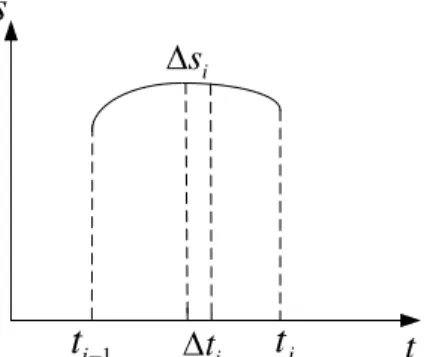
During the motion of mechanism, the contact point of joints keeps on changing, and the contact force and slide distance are different in different moment. Assuming that the contact between journal and bearing is not changed at each instant, the wear amount at each increment is considered as constant. Therefore, the continuous contact process is discreted. The curve s, as shown in Figure 5, represents a continuous sliding curve of journal relative to bearing. Ds represents a sliding distance in a sufficiently small time, Dti. Thus, the sliding distance can be obtained as(Mukras, 2010):
( ) ( )
i J i
s R d t
D = + DF (19)
Latin American Journal of Solids and Structures 11 (2014) 2624-2647
i
s
i
t
t
i1
i
t
t
s
Figure 5: Discretization sliding distance.
4 DYNAMICS ANALYSIS AND WEAR ANALYSIS INTEGRATION
In order to predict the wear at the joint during the service life of the system, it is necessary to integrate the wear prediction procedure into the system dynamics. The main computational process for wear prediction of multibody system considering clearance joint includes two steps, which are dynamics analysis and wear analysis.
The first step of the integration process is dynamics analysis of multibody system with clearance joint. The dynamics model of multibody system with clearance is established and the dynamics simulation is implemented to analyze the dynamics characteristics of mechanical system with clearance and determine the contact forces of clearance joint.
The second step of the integration process is wear analysis. The wear depth of clearance joint is calculated based on the Archard’s wear model. The amount of wear is determined at each region based on the reaction force and sliding distance from the previous analysis and is summed (according to Eq.(17)) up to obtain the total wear. Then, the geometric surfaces of journal and bearing are re-configured.
The wear is estimated and the geometry is updated to reflect the wear. The evolving geometry must also be reflected in the dynamics analysis. This can be done by noting that the value of the clearance will no longer be a constant but will depend on the new radii of bearing and journal, as defined in Eq. (18), at the contact point (as shown in Figure 3). Once the value of the clearance at the contact point has been obtained, the penetration at that point can then be obtained using Eq. (5). Besides, the contact force model can then be updated with the new values of radii of bearing and journal, that is, the nonlinear stiffness coefficient, as defined in Eq. (9), is updated according to the new radii of bearing and journal.
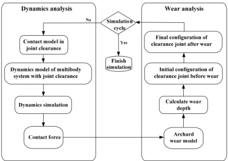
The integration frame of dynamics analysis and wear analysis is shown as Figure 6. The computational process of clearance joint wear prediction integrating dynamics analysis and wear analysis is shown in Figure 7.
The detailed processes are as follows:
(1) Establish the contact force model of clearance joint, including normal contact force model and tangential friction force model;
(2) Establish the dynamics model of multibody system with joint clearance;
Latin American Journal of Solids and Structures 11 (2014) 2624-2647
(4) Calculate the wear depth of clearance joint based on the Archard’s wear model; (5) Put the wear amount to the initial configuration of clearance joint before wear; (6) Determine the final journal and bearing radii after wear.
(7) Return to step (1) and the contact force model is updated with the new values of radii of bearing and journal.
Dynamics Analysis Wear Analysis Contact force determination
Joint geometry re-configuration Dynamics responses analysis
Wear characteristics analysis
Figure 6: Dynamics and wear analysis integration frame.
Figure 7: Computational frame of dynamics and wear analysis integration.
5 DEMONSTRATIVE APPLICATION TO A FOUR-BAR MECHANISM
Latin American Journal of Solids and Structures 11 (2014) 2624-2647
x
y
4
l
3
l
2l
O
C
B
A
Crank
Couple
Follower
Ground
1
l
Figure 8: Four-bar mechanism with a clearance joint between couple and follower (Joint B).
The four-bar mechanism consists of four rigid bodies that represent the crank, coupler, follower and ground. Figure 8 depicts the kinematic configuration of the four-bar mechanism. The joints of this mechanism include three ideal revolute joints connecting the ground to the crank, the crank to the coupler and the ground to the follower. A revolute joint with clearance exists between the couple and follower, in which the clearance is zoomed-in. The length and inertia properties of the four-bar mechanism components are listed in Table 1 and the parameters used in the dynamic simulations are given in Table 2.
In the dynamic simulation, the crank is the driving link and rotates at a constant angular velocity of 600 r/min. The initial clearance size is considered as 0.5 mm. The initial configuration corresponds to crank and ground is vertical and initial angular velocity is zero. Initially, the journal and bearing centers are coincident. Long time simulations are performed and the results presented below are plotted against to full crank rotations after steady-state has been reached.
Body Length(m) Mass(kg) Moment of inertia(kgm2)
Crank 0.55 3.6235 0.10214
Couple 0.36 2.4394 0.031428
Follower 0.64 4.1894 0.15796
Ground 0.21 - -
Table 1: Geometric and inertia properties of the four-bar mechanism.
Restitution coefficient 0.9
Dynamic friction coefficient 0.1
Young’s modulus 207GPa
Poisson’s ratio 0.3
Dimensionless wear coefficient 1.736×10⁻⁴ Hardness of the material 2.17×10⁹Pa
Latin American Journal of Solids and Structures 11 (2014) 2624-2647
5.1 Dynamics analysis
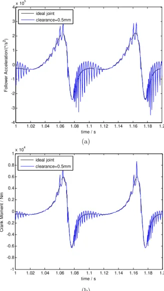
The dynamic responses of the four-bar mechanism with initial clearance are obtained and represented in Figure 9. Two different kinds of results are presented. One is all the joints of four-bar mechanism are considered as ideal, in which no clearances exist. The other is the mechanism is simulated with a revolute joint clearance, which between couple and follower (as shown in Figure 8).
(a)
(b)
Figure 9: Dynamic characteristics of mechanism with initial constant clearance ((a) Follower angular
acceleration; (b) Crank moment required to maintain the crank angular velocity constant).
Figure 9(a) by the time plots is the angle acceleration of the follower. The moment acting on the crank, which is required to maintain the crank angular velocity constant, is represented in Figure 9(b). The contact force in revolute clearance joint is plotted in Figure 10. The relative motion between the journal and bearing centers is plotted in Figure 11. Note that results are plotted against those obtained for ideal joints, being reported for two full crank rotations after steady-state has been reached.
1 1.02 1.04 1.06 1.08 1.1 1.12 1.14 1.16 1.18 1.2 -4
-3 -2 -1 0 1 2 3 4x 10
5
time / s
F
o
llow
er
A
c
c
e
le
ra
ti
on
/(
°/
s
2)
ideal joint clearance=0.5mm
1 1.02 1.04 1.06 1.08 1.1 1.12 1.14 1.16 1.18 1.2 -1
-0.8 -0.6 -0.4 -0.2 0 0.2 0.4 0.6 0.8
1x 10
4
time / s
C
ra
n
k
Mo
me
n
t /
N
m
Latin American Journal of Solids and Structures 11 (2014) 2624-2647
In Figure 9(a), the angular acceleration of the follower shows significant differences between the dynamic response of the mechanism when modeled with and without joint clearance. The existence of clearance affects the angular acceleration of follower by leading to vibration. The sudden changes in angular acceleration of follower are due to the impact between the journal and bearing for the clearance joint. The angular acceleration of follower with clearance is obviously shaky and presents high peaks of its values, which indicates that, when considering the clearance, the existence of clearances will cause oscillation of the four-bar mechanism and influence the dynamic responses of the system. The same phenomenon can be observed in the curve of crank moment, which is required to maintain the crank angular velocity constant, presented by Figure 9(b). Furthermore, the system’s response repeats itself from cycle to cycle clearly.
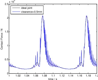
Figure 10 shows that the existence of clearance leads to the impact force in joint increase, and the impact force is high-frequency oscillation. The contact force changes periodically, repeatedly and severely. In each cycle, the contact force is very large in certain range of revolute angle, which explains the acceleration characteristics in Figure 9(a). Figure 11 shows that the journal is always in contact with the bearing wall. This observation is logical since the two bodies are moving in the same direction. And the journal and bearing contact frequently in some special regions.
Figure 10: Contact force in clearance joint.
5.2 Wear analysis
Further, the wear amount of revolute clearance joint is analyzed. As far as the wear is concerned, it must be highlighted that the wear coefficient used to perform the numerical simulations was selected upon the best published data (Bhushan, 2002). In order to analyze the wear phenomenon of revolute clearance joint in multibody mechanical system, long time simulations are performed. Due to the wear amount of clearance joint is very small in one crank rotation, here, for wear phenomenon analysis purposes only, wear period is proposed and defined for a certain crank rotations, that is, the final journal and bearing radii of revolute clearance joint caused by wear are determined and re-configured when a wear period are reached. Therefore, when the mechanism is working for one wear period, the wear amount of clearance joint is calculated and
1 1.02 1.04 1.06 1.08 1.1 1.12 1.14 1.16 1.18 1.2 0
0.5 1 1.5 2 2.5x 10
4
time / s
C
o
nt
ac
t F
or
c
e /
N
Latin American Journal of Solids and Structures 11 (2014) 2624-2647
the journal and bearing radii caused by wear are determined and re-configured. The clearance is also calculated and updated. Due to the wear amount of clearance joint is very small in one crank rotation, here, for improving the computational efficiency purposes only, the dynamics simulation is carried out in the new profile of the joint assuming the clearance is not changed in one wear period.
Figure 11: Journal center trace relative to the bearing center.
For the first wear period of mechanism motion, the wear depth of clearance joint is presented in Figure 12. In Figure 12, the wear depth is plotted against the crank angle. It is well visible that the wear phenomenon does not affect the entire joint surface in the same manner with crank motion position during the mechanism motion period, but mostly the wear occurs on specific regions. The wear is much more accentuated in the range 260-300° of the crank angle. This observation is supported by the fact that the contact between the journal surface and bearing wall is wider and more frequent in this angular range of crank, it also can be observed by Figure 10 and Figure 11.
Figure 12: Wear depth of clearance joint.
-6 -4 -2 0 2 4 6
x 10-4 -6
-4 -2 0 2 4 6x 10
-4
X / m
Y /
m
Clearance Circle
0 90 180 270 360
0 0.2 0.4 0.6 0.8 1 1.2 1.4x 10
-4
Crank angle /°
Wear
dept
h /
Latin American Journal of Solids and Structures 11 (2014) 2624-2647
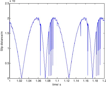
Figure 13 represents the sliding distance of clearance joint. It shows that the sliding distance of journal relative to bearing is not continuous and smooth. The sliding distance is dynamic changing. It indicates that the severe changes of sliding distance will cause journal wear severely. Figure 14 shows the contact angle curve of journal and bearing. Contact angle represents the angle in continuous contact of journal and bearing in clearance joint. It shows that the contact angle curve is not smooth. The contact angle is obvious oscillating in some positions due to the high speed of the mechanism, which indicates that the repeating contact deformations are existence in these positions of clearance joint. Therefore, the contact forces in the positions are higher and oscillating, which leads to wear severely of the clearance joint. Compare Figure 13 and Figure 14, it can be found the severe wear position is the same.
Figure 13: Sliding distance.
Figure 14: Contact angle.
1 1.02 1.04 1.06 1.08 1.1 1.12 1.14 1.16 1.18 1.2 0
0.5 1 1.5 2 2.5x 10
-3
time/ s
S
lip di
s
tanc
e/
m
1 1.02 1.04 1.06 1.08 1.1 1.12 1.14 1.16 1.18 1.2 -2
-1.5 -1 -0.5 0 0.5 1 1.5 2
C
ont
ac
t an
gl
e
/
rad
Latin American Journal of Solids and Structures 11 (2014) 2624-2647
Further, the effect of the wear depth on the journal surface is illustrated in Figure 15, where the initial and final geometric configurations are presented and compared. Here, and for wear phenomenon analysis purposes only, the wear profile on the journal is subtracted to a circle of 100 µm, in order to illustrate the wear phenomenon. As it is shown, the final configuration is not regular due to the non-uniform wear produced around the journal surface. After wear of clearance joint, the radius of journal is not a constant value, but various around the journal surface. In addition, the surface of journal is smooth, indicating that the journal and bearing continuous contact during steady-state work of mechanism and there are no pits in the surface of journal, which is agree with the actual situation.
Figure 15: Wear profile on the journal (subtracted to a circle of 100 µm).
Similarly, after clearance joint wear, the clearance size is increased and not a constant value, which can be seen from Figure 16. This observation is supported by the fact that the contact between the journal surface and bearing wall is wider and more frequent in special regions of clearance joint, which causes that joint wear non-regularly.
Figure 16: Clearance change after joint wear.
5e-005 0.0001
0.00015m
30
210
60
240
90°
270° 120
300 150
330
180° 0°
Initial profile Final profile
0.0002 0.0004
0.0006m
30
210
60
240
90°
270° 120
300 150
330
180° 0°
Latin American Journal of Solids and Structures 11 (2014) 2624-2647
Further, in order to predict the wear of clearance joint throughout a long time working of the system, the wear prediction of clearance joint for two wear periods and three wear periods are presented and discussed.
Figure 17(a) shows the wear depth accumulated for two wear periods. Figure 17(b) shows the wear depth accumulated for three wear periods. In Figure 17, the wear depth is plotted against the crank angle. It is well visible that the wear phenomenon does not affect the entire joint surface in the same manner with crank motion position during the mechanism motion period, but mostly the wear occurs on specific regions. Compare Figure 12, it can be found the severe wear positions are the same. However, the wear depth increases as the mechanism motion time extends.
(a)
(b)
Figure 17: Sum wear depth of clearance joint ((a): two wear periods; (b) three wear periods).
0 90 180 270 360
0 1 2 3x 10
-4
Wear D
ept
h/
m
Crank Angle/°
0 90 180 270 360
0 0.5 1 1.5 2 2.5 3 3.5 4 4.5x 10
-4
W
ear
D
ept
h/
m
Latin American Journal of Solids and Structures 11 (2014) 2624-2647
The effect of the wear depth on the journal surface is illustrated in Figure 18, where the initial and final geometric configurations are presented and compared. Figure 18(a) shows the wear depth on the journal surface for two wear periods, here, for wear phenomenon analysis purposes only, the wear profile on the journal is subtracted to a circle of 100 µm, in order to illustrate the wear phenomenon. Figure 18(b) shows the wear depth on the journal surface for three wear periods, here, for wear phenomenon analysis purposes only, the wear profile on the journal is subtracted to a circle of 200 µm, in order to illustrate the wear phenomenon.
(a)
(b)
Figure 18: Wear profile on the Wear profile on the journal ((a): two wear periods, subtracted to a circle of 100
µm; (b): three wear periods, subtracted to a circle of 200 µm).
As it is shown, the final configuration is not regular due to the non-uniform wear produced around the journal surface. The wear depth on journal increases as the mechanism motion time extends. Besides, the final configurations of journal are different.
5e-005 0.0001
0.00015m
30
210
60
240
90°
270° 120
300 150
330
180° 0°
initial profile final profile
0.0001 0.0002m
30
210
60
240
90°
270° 120
300 150
330
180° 0°
Latin American Journal of Solids and Structures 11 (2014) 2624-2647
Similarly, after clearance joint wear, the clearance size is increased and not a constant value, which can be seen from Figure 19. Figure 19(a) shows the clearance for two wear periods. Figure 19(b) shows the clearance for three wear periods.
Figure 19 shows that the clearance size is increasing with the mechanism motion time extends and not regular. This observation is supported by the fact that the contact between the journal surface and bearing wall is wider and more frequent in special regions of clearance joint, which causes that joint wear non-regularly. Figure 19 (a) shows that the maximum clearance size is 0.6806 mm for two wear periods, however, the initial regular clearance size is 0.5mm. So the clearance size after wear increases by 36.12% than the initial clearance. Figure 19 (b) shows that the maximum clearance size is 0.7659 mm for three wear periods and the clearance size after wear increases by 51.38% than the initial clearance. It can be found that the wear depth and clearance size increase as the mechanism motion time extends. These values represent how the level of clearance is increased because of the wear within the joint clearance.
(a)
(b)
Figure 19: Clearance after wear ((a): two wear periods; (b): three wear periods).
0.0002 0.0004
0.0006 0.0008m
30
210
60
240
90
270° 120°
300 150
330
180° 0°
initial clearance final clearance
0.0002 0.0004
0.0006 0.0008
0.001m
30
210
60
240
90°
270° 120
300 150
330
180° 0°
Latin American Journal of Solids and Structures 11 (2014) 2624-2647
Figure 20 shows the journal center traces in each wear period, respectively. It shows that the journal traces are different. Compare Figure 16 and Figure 19, it can be found the journal center traces are according to the clearance configuration. In addition, the journal is always in contact with the bearing wall for the three cases. This observation is logical since the two bodies are moving in the same direction. And the journal and bearing contact frequently in some special regions.
(a) (b)
(c)
Figure 20: Journal center trace ((a): in first wear period; (b): in second wear period; (c) in third wear period)).
6 CONCLUSIONS
In this work, the wear phenomena of multibody mechanical system considering dry revolute clearance joint are investigated using a computational methodology. The wear prediction of
-8 -6 -4 -2 0 2 4 6 8
x 10-4 -8
-6 -4 -2 0 2 4 6 8x 10
-4
X / m
Y / m
ideal joint(without clearance)
1st periodic trace(initial clearance=0.5mm)
-1 -0.8 -0.6 -0.4 -0.2 0 0.2 0.4 0.6 0.8 1 x 10⁻³ -1
-0.8 -0.6 -0.4 -0.2 0 0.2 0.4 0.6 0.8
1x 10
-3
X / m
Y / m
ideal joint( without clearance) 2nd periodic trace(non-regular clearance)
-1 -0.8 -0.6 -0.4 -0.2 0 0.2 0.4 0.6 0.8 1 x 10⁻³ -1
-0.8 -0.6 -0.4 -0.2 0 0.2 0.4 0.6 0.8
1x 10
-3
X / m
Y / m
Latin American Journal of Solids and Structures 11 (2014) 2624-2647
clearance joint is presented by integrating the dynamics model of mutibody system with wear model. The main computational process for wear prediction of multibody system considering clearance joint includes two steps, which are dynamics analysis and wear analysis. The first step of the integration process is dynamics analysis of multibody system with clearance joint. The second step of the integration process is wear analysis. The contact force model of revolute joint with clearance in multibody systems is established using a hybrid nonlinear continuous contact force model. And the friction effect is considered by using a modified Coulomb friction model. The wear modeling of revolute clearance joint in multibody systems is presented based on the Archard’s wear model. Then the integration frame of dynamics analysis and wear analysis is presented. Finally, a four-bar multibody mechanical system is used as numerical example application to perform the investigation.
The numerical simulation results indicate that wear of clearance joint in multibody mechanical system can not be ignored. The existence of clearance leads to impact force in joint increase and the impact force is oscillation with high amplitude. In addition, the amplitude of impact force increases from the mechanism without clearance, which indicates that the impact force causes by clearance will lead to severe wear of joint.
Further, the wear amount of revolute clearance joint is predicted. It shows that the wear depth along the joint surface is not uniform, but more severe in some regions, due to the face that the contact between the joint elements is wider and more frequent in some specific regions. After wear of clearance joint, the radius of journal is not a constant value, which leads to the clearance size increase and not constant.
Besides, the maximum clearance sizes are 0.6806 mm and 0.7659 mm for two wear periods and three wear periods, respectively. However, the initial regular clearance size is 0.5mm. So the clearance size after wear increases by 36.12% and 51.38% than the initial clearance. It can be found that the wear depth and clearance size increase as the mechanism motion time extends. These values represent how the level of clearance is increased because of the wear within the joint clearance.
This work presents an effective method to predict wear of revolute joint with clearance by integrating dynamics model and wear model. The work indicates that wear leads to the clearance larger and non-regular change. It is not precise that the clearance joint is not wear and clearance considered as a constant value throughout the service life of the system. It is importance to take into consideration the effects of wear in the geometrical changes on the joint surfaces and clearance.
Acknowledgments
Latin American Journal of Solids and Structures 11 (2014) 2624-2647
References
Bai, Z.F. and Zhao, Y., (2012). Dynamic behaviour analysis of planar mechanical systems with clearance in revolute joints using a new hybrid contact force model, International Journal of Mechanical Sciences, 54: 190-205.
Bauchau, O.A., Rodriguez, J., (2002). Modeling of Joints with Clearance in Flexible Multi-body System. International Journal of Solids and Structures, 34: 41-63.
Bauchau, O.A., Ju, C.K., (2006). Modeling friction phenomena in flexible multibody dynamics. Computer Methods in Applied Mechanics and Engineering, 195: 6909-6924.
Bhushan, B., (2002). Introduction to Tribology, New York: John Wiley and Sons Press
Bing, S., Ye, J., (2008). Dynamic analysis of the reheat-stop-valve mechanism with revolute clearance joint in consideration of thermal effect. Mechanism and Machine Theory, 43(12): 1625-1638.
Erkaya, S., Uzmay, I., (2010). Experimental investigation of joint clearance effects on the dynamics of a slider-crank mechanism. Multibody System Dynamics, 24: 81-102.
Erkaya S., (2012). Investigation of joint clearance effects on welding robot manipulators. Robotics and Computer-Integrated Manufacturing, 28: 449-457.
Flodin, A., Andersson, S., (2000). Simulation of mild wear in helicoidal gears, Wear 241:123-128.
Flores, P., Ambrósio, J., Claro, J.P., (2004). Dynamic Analysis for Planar Multibody Mechanical Systems with Lubricated Joints, Multibody System Dynamics, 12: 47-74.
Flores, P., Ambrosio, J., Claro, J.C.P., Lankarani, H.M., Koshy, C.S., (2006). A study on dynamics of mechanical systems including joints with clearance and lubrication. Mechanism and Machine Theory, 41: 247-261.
Flores, P., (2010). A parametric study on the dynamic response of planar multibody systems with multiple clearance joints. Nonlinear Dynamics, 61: 633-653.
Garcia, O.J.C., (2005) Analysis of Clearance in Multibody System, Multibody System Dynamics 13: 401-420.
Khemili, I., Romdhane, L., (2008). Dynamic analysis of a flexible slider-crank mechanism with clearance. European Journal of Mechanics A/Solids 27: 882-898.
Koshy, C.S., Flores, P., Lankarani, H.M., (2013). Study of the effect of contact force model on the dynamic response of mechanical systems with dry clearance joints: computational and experimental approaches. Nonlinear Dynamics, 73: 325-338
Meng, H.C., Ludema, K.C., (1995). Wear models and predictive equations: their form and content, Wear, 181-183: 443-457.
Muvengei, O., Kihiu, J., Ikua, B., (2013). Dynamic analysis of planar rigid-body mechanical systems with two-clearance revolute joints. Nonlinear Dynamics, 73: 259-273
Mukras, S., Kim, N.H., Mauntler, N.A., Schmitz, T., Sawyer, W.G., (2010). Comparison Between Elastic Foundation and Contact Force Models in Wear Analysis of Planar Multibody System, Trans Transactions of the ASME: Journal of Tribology, 132: 1-11.
Nayak, N., Laksminarayanan, P.A., Badu, M.K.G., Dani, A.D., (2006). Predictions of cam follower wear in diesel engines, Wear, 260: 181-192.
Põdra, P., Andersson, S., (1999). Finite element analysis wear simulation of a conical spinning contact considering surface topology, Wear, 224: 13-21.
Schwab, A.L., Meijaard, J.P., Meijers, P.A., (2002). Comparison of Revolute Joint Clearance Model in the Dynamic Analysis of Rigid and Elastic Mechanical Systems. Mechanism and Machine Theory, 37(9): 895-913.
Latin American Journal of Solids and Structures 11 (2014) 2624-2647
Tasora, A., Prati, E., Silvestri, M., (2004). Experimental investigation of clearance effects in a revolute joint, in: Proceedings of the 2004 AIMETA International Tribology Conference, Rome, Italy, September 14-17, 1-8
Tian, Q., Zhang, Y.Q., Chen, L.P., Flores, P., (2009). Dynamics of Spatial Flexible Multibody Systems with Clearance and Lubricated Spherical Joints. Computers and Structures, 87: 913-929.