Marcia M. Maru
[email protected]and Deniol K. Tanaka
Escola Politécnica da Universidade de São Paulo Department of Mechanical Engineering Av. Prof. Mello Moraes 2231 05508-900 São Paulo, SP. Brazil [email protected]Influence of Loading, Contamination
and Additive on the Wear of a Metallic
Pair under Rotating and
Reciprocating Lubricated Sliding
This paper deals with an experimental study of wear and friction responses from lubricated sliding. Tests were carried out using a tribometer having devices for both continuous and reciprocating motion. The tested specimens were pins of AISI 52100 steel and counter-faces of AISI 8640 steel. The lubricant was paraffin mineral oil, VI 100. The presence of additives and contamination in the lubricant was investigated under two mechanical loading levels, determined by the velocity/load relation. Wear was evaluated in terms of morphology of the worn surfaces and by dimensional analysis of worn area of the pins. It was possible to obtain a ranking of influences on wear of mechanical loading, mechanical motion, oil additive and contamination presence in oil.
Keywords: Wear, paraffin oil, abrasive contaminant, rotating motion, reciprocating motion, mechanical loading, mixed lubrication
Introduction
It is known that surface interactions control the performance of most mechanical systems. In lubricated systems, lubricant plays the essential role in wear and friction reduction of the sliding parts. According to Persson (1998), even a monolayer of lubricant at contact interface is able to change the tribological response of the system. Advancement in oil-surface interaction knowledge is needed for development of better lubricants and materials for tribological purposes. In practice, new lubricant alternatives for tribological purposes are often investigated through laboratory-simulated mechanical systems. Such experimental approach has a critical point: identification of relevant tribological variables. In order to minimize cost of laboratory simulation, simplified tentative solutions are commonly adopted. However, every simplification involves risks when selecting the relevant variables of a real system. On the other hand, use of conventional laboratory tribometers is frequently seen for variables identification task. In this case, investigations are mostly oriented specifically for evaluating materials performance, seeming that care on lubrication regime simulation of a practical application in the tribometer is considered not important. Lubrication can be affected by variables such as mechanical loading and lubricant characteristics, being examples the presence of additive and contaminant.1
Literature information shows that the chemical nature of lubricant changes friction response of the system. For instance, metal-metal contact and consequent high wear and friction can be avoided with the use of adequate boundary lubricants. They can act by forming protective films with repulsive forces, which are able to prevent solid contact, then reducing growth of metallic junctions (Hutchings, 1992). Chemical nature of films depends on adsorption characteristics of polar groups of the boundary lubricant on the metallic surfaces. Efficiency of boundary lubricant is related to its “oiliness”, sometimes called “lubricity”. Lubricity of base oil can be improved by the use of additives such as fatty acids (Hutchings, 1992). Additives such as EP and anti-wear ones are chemical substances that react with the sliding surfaces in localized areas, forming low shear strength films at the contact regions under severe thermomechanical loading (Hutchings, 1992). Blau (1996) mentioned a mechanism for wear and friction lowering promoted by phosphorus-containing additives through eutectic phosphides
Paper accepted January, 2006. Technical Editor: Paulo Eigi Miyagi.
production at the friction-heated spots. The effect on wear of phosphorus-containing additives is discussed in the present work.
Although most investigations mention wear reduction when lubricant additives are used (Wang, Cheng and Gwan, 1995; Wan, Pu and Xue, 1996), it cannot be generalized. Jahanmir (1987), in lubricated sliding tests at a range of loads (150 to 3,000 N), verified wear reduction when using oil with additives only under low loads. On the contrary, wear increased at high loads and its mechanism changed from ploughing to delamination, which indicates surface material change due to chemical action of oil additive.
Presence of abrasive contaminant is another significant factor to be considered in lubricated systems. Studies have shown that it increases both wear of the contacting bodies and friction coefficient (Mehan, 1988); however, this behavior depends on the nature of materials, as shown by Mehan, Flynn and Glammarise (1991) in reciprocating block-on-ring tests, with diesel oil at 177 ºC, contaminated with Al2O3 abrasive, rings of tungsten carbide and blocks, coated with several materials (tungsten carbide, chromium and chromium carbide). The rings had worn similarly in the tests in clean and contaminated oil, while the blocks, specially those chromium-coated, had wear increase when oil was contaminated, due to their low thermo-mechanical strength.
J. of the Braz. Soc. of Mech. Sci. & Eng. Copyright 2006 by ABCM
Figure 1. Indentation and cut caused by an abrasive particle in lubricated system (Xuan, Hong and Fitch, 1989).
In this Figure, a fluid film with thickness h separates the solid surfaces. Size of the particle is in a critical range able to penetrate the space between the body and the counter-body, to causing abrasion. When differences in hardness are high, particle is able to penetrate the material of lower hardness and cuts the harder surface. When differences are small, particle can either cut both surfaces or be broken, depending on hardness ratio of the abrasive to the surface materials. Critical aspect for the action of those mechanisms is the dependence on the distribution uniformity of particles along oil film layer, besides the particles size and geometry (Williams and Hyncica, 1992).
After considering some influencing parameters on tribological performance of lubricated tribopairs, it is pointed out that conventional laboratory tests are essential since they provide opportunities of studies on basic wear mechanisms. However, in order to evaluate the usefulness of laboratory tests results in practice, it is necessary to analyze existing potentialities and limitations of these tests. For instance, it is known that four-ball tests are able to evaluate tribological performance under extreme operating conditions; however, they could be inadequate for evaluating tribological behavior of systems that do not operate in such conditions. The lubrication regime and the related friction phenomena in conventional tribometer can be very different from practical situation. With wear produced in accelerated way, interaction mechanisms among the surfaces will be more severe than those found in practical situations. In practical sense, as pointed out by Dowson (1997), in order to have real tribossystems adequately simulated in laboratory, it is necessary to know the operation of the real system and their most relevant tribological variables; on the contrary, the laboratory simulation using conventional tribometers can lead to erroneous indications concerning the actual performance. On the other hand, knowledge improvement on potentialities and complexities involved in the conventional tests is also required, in order to gain benefits in the use of tribological studies performed by conventional machines. Investigation of variables and their effects on the tribological performance in the tests with such machines is thought to be required, not only in terms of operational conditions but also regarding the differences among the systems. In the case of lubricated systems, characterization of the lubrication influence is emphasized.
It is largely noticed that fundamental research in lubricated sliding is mostly conducted with systems with continuous motion, such as four-ball, ring-on-block and pin-on-disk assemblies. Sliding lubricated studies through reciprocating pin-on-plate machines (Cavdar, 1997; Culer et al., 1999; Martin et al., 1999; Maru and Sinatora, 2001) are also seen. In general, there is no fundamental reason why the continuous or the reciprocating system is chosen; option is generally based on similarity between the type of motion of the laboratory system and the actual application being studied
(Maru, 1998). In terms of tribological differences between the continuous and the reciprocating systems related to lubrication, no investigations were found. Concerning dry sliding systems, short number of investigations can be found. Some of these showed that both wear and friction are higher for continuous sliding system. Blau and Waluskas (2000) explained the higher wear and friction as caused by the formation of lips at lateral edges of the wear track, called “built-up edge”, more likely to happen in continuous sliding systems. It was also confirmed by Marui and Endo (2001). As sliding proceeds, depending on the test conditions, presence of debris particles in the contact area can change wear and friction behavior. Hwang, Kim and Lee (1999) conducted rotating and reciprocating dry tests with a device to observe particles in the contact area during the test. The authors observed higher wear and friction in continuous than in reciprocating tests, the difference was in particles clustering into the contact area, which was more evident in continuous unidirectional sliding. Odabas and Su (1997) also investigated the comparative performance between unidirectional and reciprocating sliding using pin on sandpaper and also concluded that wear is lower in reciprocating sliding. They explained it by the differences in the run distances and in the amount of particles in the wear track, with larger amount in the unidirectional tests. Larger particles amount in the contact in unidirectional sliding is certainly related to small centrifugal force action on the particles, since track radius of the unidirectional sliding was smaller than the length of the reciprocating stroke (35 mm to 220 mm).
On the other hand, reciprocating, compared to unidirectional machines, can be considered as more severe to wear in terms of surface stressing. Ward (1970) studied reciprocating and rotating tribossystem configurations and their influences on dry wear of steel bodies. He observed that wear in reciprocating sliding condition was higher than in continuous sliding tests. He also observed that the load for wear transition from mild to severe regime was lower in reciprocating sliding. He related it to two main differences: surface stressing and amount of remaining wear particles in the wear track; both larger in reciprocating sliding. Differences in wear of tested specimens related with the type of system motion are also discussed in the present work.
In order to improve practical use of results obtained from laboratorial tests, it is emphasized the need of identifying how wear and friction are affected by simultaneous interaction of variables such as loading, oil contamination, oil additive presence and the mechanical system configuration.
Experimental Procedure
Sliding tests were conducted through a TE-67 Plint & Partners tribometer with two configurations: rotating pin-on-disk (D tests) and reciprocating pin-on-plate (P tests). Figure 2 shows the schematic representation of both tribossystems.
(a)
(b)
Figure 2. (Continued).
Disk track radius (R) is equivalent to ½ plate stroke length. Maximum sliding velocity (V) in reciprocating motion occurs at half-track length of plate and is equivalent to the tangential velocity in continuous motion, being V=2.π.f.R, where f is the disk rotational speed or the plate oscillation frequency. The mean sliding velocity in reciprocating motion is V=4.f.R.
Both devices have normal loading pneumatically applied on the pin specimen. Oil bath lubricates the tribocontact to be tested, heated by electrical resistors under the plate/disk. Friction force can be monitored throughout the tests; data in the performed tests were acquired at every 10 s.
Every sliding test was run with a previous step of 1,200 s (0.33 h) for oil heating up to 100 ºC, at the test velocity without loading. After the previous step, load was applied and then 50,000 pin cycles were run on the disk in the D tests (equivalent to 100,000 pin cycles on the plate in the P tests). Two loading levels were selected, considering the normal load to average sliding velocity (V/W) ratio. Ratios were selected observing, in previous analyses, capability of oil to be kept in the contact during the sliding without being swept away by centrifugal force. The tests with mild loading level were coded as PP and DD and with severe as P and D. Table 1 summarizes the test conditions. According to the IRG diagram, which roughly indicates the transition curves among lubrication regimes based on load and velocity values (Gee, Begelinger and Salomon, 1984), the tests were conducted under mixed lubrication conditions. Figure 3 shows the IRG diagram with the selected test conditions.
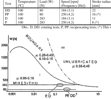
Table 1. Summary of the testing conditions.
Test Temperature [ºC] Load (W) [N] Speed [rpm] (Frequency [Hz]) Stroke radius [mm] Average velocity (V) [m/s] Mechanical loading (V/W) Distance [m] Time [h] Cycles
DD 100 80 184 (3.1) 22 0.42 Mild 6,912 4.5 50,000
PP 100 80 250 (4.2) 16 (*) 0.27 Mild 3,200 3.3 100,000
D 100 283 184 (3.1) 11 0.21 Severe 3,456 4.5 50,000
P 100 283 250 (4.2) 8 (*) 0.13 Severe 1,600 3.3 100,000
Obs.: D, DD: rotating tests; P, PP: reciprocating tests; (*) This value corresponds to the ½ stroke in the reciprocating motion.
Figure 3. IRG Diagram (Gee, Begelinger and Salomon, 1984) showing the selected testing conditions.
The pin material was of AISI 52100 steel, with 3 mm diameter and 23.8 mm long and test surface rounded to 5.5±0.3 mm radius2. Measured hardness was 63±0 HRc (25 kg). Figure 4(a) shows the top view of a pin. Some morphology similar to microcraters can be observed. The Ra (mean height of asperities) roughness of surface was 0.51±0.05 µm (1.25 mm measurement length). The disk and plate material was of AISI 8640 steel, quenched and tempered to 48±1 HRC hardness. The disks were machined to 75 mm diameter and 8 mm thickness and the plates to 58 mm x 38 mm x 4 mm. The surfaces were ground-finished, shown in Fig. 4(b) and 4(c). More randomly finished surface is noticed in the disk than in the plate. Ra roughness of disks was 0.65±0.15 µm, and 1.3±0.2 µm for plates.
2 Needles rollers (NRA code), BR019 Catalogue, Rolamentos Schaeffler do
Brasil, 1998.
As lubricants, paraffin base oils were used, one with and another without additives. Both oils, of same viscosity index (VI 100), are commercial and normally recommended for gearbox lubrication3. Oil with additives had additive pack of less than 3 % in mass, composed by alkyl phosphate and sulfured fatty acids with anticorrosive, antirust, antioxidant, anti-wear, extreme pressure (EP) and anti foaming properties. Optical emission spectrometry analysis in this oil showed 354 µg/g of phosphorus. It was also analyzed by infra-red spectrometry, which detected presence of sulfur. SA code was used for the tests without additive and CA for the tests with additive.
(a)
Figure 4. Microscopic observation of surfaces of the test specimens. (a) Pin; (b) disk; (c) plate.
3 Without additives oil: Vitrea 100 designation, Shell Company. Oil with
J. of the Braz. Soc. of Mech. Sci. & Eng. Copyright 2006 by ABCM
(b)
(c)
Figure 4. (Continued).
Quartz (SiO2) of 1,000 HV average hardness and 15 µm average particle size, was used as abrasive contaminant, in 0.5 mg/ml concentration in oil. Tab. 2 shows the codes used for the tests. At least three tests were run in each condition.
Table 2. Codification for the performed sliding tests.
Code Loading Additive Contaminant System
PP SA Mild No No Reciprocating
DD SA Mild No No Rotating
P SA Severe No No Reciprocating
D SA Severe No No Rotating PPc SA Mild No Yes Reciprocating
DDc SA Mild No Yes Rotating
Pc SA Severe No Yes Reciprocating
Dc SA Severe No Yes Rotating
Code Loading Additive Contaminant System
PP CA Mild Yes No Reciprocating
DD CA Mild Yes No Rotating
P CA Severe Yes No Reciprocating
D CA Severe Yes No Rotating
PPc CA Mild Yes Yes Reciprocating
DDc CA Mild Yes Yes Rotating Pc CA Severe Yes Yes Reciprocating
Dc CA Severe Yes Yes Rotating
After the tests, the contact surfaces were examined by optical and scanning electron microscopes. Wear was evaluated by measurements of the pin worn area, through image analysis software (Leica Qwin Standard V.2.2). Average values of the friction coefficient monitored during the tests were also analyzed.
Results
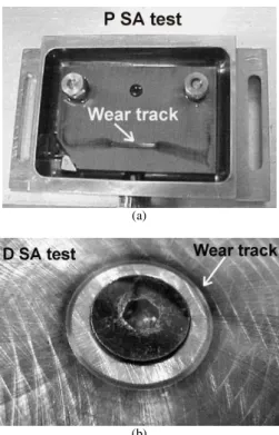
A way to evaluate wear is by measuring the projected area of the pin worn surface. Figure 5 shows an example of the performed measurement, obtained from a P SA test.
Figure 5. Illustrative example of area measurement of a tested pin.
Table 3 shows values of the worn area of the pins. Values were normalized by run distance in order to obtain comparable wear rates. In fact, it is seen that wear ranked from DD series to P series.
Table 3. Average values of wear-affected pin surface areas.
Test code Area
[Φ103
µm2] Std dev [Φ103
µm2] Run distance
[m]
Normalize d area [µm2/m]
Std dev [µm2/m]
DD CA 166 22 6,912 24 3
DDc CA 602 273 6,912 87 40
DD SA 576 218 6,912 83 32
DDc SA 559 78 6,912 81 11
PP CA 298 45 3,200 93 14
PPc CA 455 29 3,200 142 9 PP SA 338 41 3,200 106 13
PPc SA 559 40 3,200 175 12
D CA 541 62 3,456 156 18
Dc CA 655 49 3,456 189 14 D SA 755 79 3,456 218 23
Dc SA 896 33 3,456 259 10 P CA 581 33 1,600 363 20
Pc CA 756 49 1,600 321 35 P SA 727 81 1,600 454 50
Pc SA 849 118 1,600 530 74
Obs.: Std dev = standard deviation of values measured in all performed tests
Figure 6. Normalized values of pin worn area of pin-on-disk tests (a) and pin-on-plate tests (b). Mechanical loading effect.
Figure 7. Normalized values of pin worn area of mild (a) and severe (b) loading tests. Oil contamination effect.
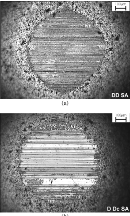
Under mild loading, positive effect of contaminant in oil on pin wear was not evident in DD SA tests. In this test condition, it can be observed (Fig. 8) that the abrasion mechanism was pronounced even without contamination in the oil. Then, abrasive contaminants added into oil acted mainly to polish the pin surface without affecting the size of the worn area. Also, it is seen that all DD tests had high standard deviation, denoting a very random test condition.
(a)
(b)
Figure 8. Microscopic morphology of the pin worn surface after (a) DD SA and (b) DDc SA tests.
Some aspects were considered in order to understand the effect of oil contamination on wear. One possible mechanism is a crush process of larger particles. As sliding proceeded, small particles could have been generated, causing then the abrasive action. Comminution mechanism in oil-contaminated tests had already been mentioned by Mehan, Flynn and Glammarise (1991).
Another possible mechanism is incrustation of abrasive particles in the counter-body surface, considering the abrasive hardness value (about 1.000 HV) compared to the counter-body (48 HRc (480 HV)) and to the pin (63 HRc (770 HV)) ones.
(a)
J. of the Braz. Soc. of Mech. Sci. & Eng. Copyright 2006 by ABCM
(b)
Figure 14. (Continued).
(a)
(b)
Figure 15. Details of cracking in the surfaces of (a) plate after P CA test and (b) disk after D CA test. Secondary electrons image.
Concerning the effect of mechanical system on wear, sub-surface examination confirms occurrence of different wear mechanisms in the tests with reciprocating and rotating motion, mainly under severe mechanical loading and oil with additive. Without additives, the lubricant film should be strongly loaded, resulting in material “dragging”, as seen in Fig. 16. Then, additive in this case acted as EP additives through formation of a protecting tribofilm, since they inhibited severe plastic deformation. In both mechanical systems, despite high dimensional wear of counter-bodies, plastic deformation has reduced due to additive in oil; also, counter-bodies material has undergone structural modification, being it more evident in the plate than in the disk. In the rotating test, tribofilm was not microscopically visible; in contrast, in the reciprocating tests, formation of a darkened tribolayer on the surfaces was very evident. Both observations suggest that stressing level was in fact higher in reciprocating tests than in rotating ones.
(a)
(b)
Figure 16. Wear affected sub-surface region of (a) plate after P SA test and (b) disk after D SA test. Nital 3% etching. Secondary electrons image.
(a)
(b)
Figure 17. Worn tracks on (a) plate and (b) disk, SA tests. Debris agglomeration just after test.
chance for oil to be renewed in the contact area during sliding because of centrifugal action in oil flux. Therefore, compact tribolayer is more difficult to be produced. Figure 17 shows debris particles deposited on the counter-bodies surface just after the test for linear and rotating motion.
There are also other factors that could contribute to the tribological differences among the tested mechanical systems. Difference in initial roughness of counter-body surfaces, 100 % higher for the plates, can also have contributed to the tribological differences among the systems tested with additived oil. Extreme pressure situation in the contact area are more likely to occur with high roughness. Another influence for the difference seen among the
tested mechanical systems is the velocity/load (V/W) ratio, slightly lower for reciprocating tests. This ratio is roughly proportional to the oil film thickness in fluid lubrication. Table 4 summarizes the main characteristics considered in the analysis of wear differences between the mechanical systems.
Despite lower run distance in reciprocating mode, pin wear was equivalent to that observed with rotating system. Figure 18 shows pin wear results normalized by run distance. It clearly shows that reciprocating system is tribologically more severe.
Table 4. Main differences between the tested mechanical systems.
Factor Reciprocating Rotating
Counter-body roughness Transversally oriented, higher Ra (1.3 µm) Randomly oriented, lower Ra (0.65 µm)
Surface stressing Cyclic Continuous
Pin cycling 100,000 cycles 50,000 cycles
Oil flux motion Escape out the contact by the lateral edges of stroke Escape out the contact is by centrifugal action
V/W rate [(mm/s)/N] Lower (0.47) Higher (0.75)
Run distance 1,600 m 3,456 m
Figure 18. Normalized values of pin worn area. Observation of the differences among the used mechanical systems.
Statistical analysis4 of pin wear values has indicated that all studied influences, namely, presences of additive and abrasive in oil, loading level and system motion, had significant effects on wear. Figure 19 shows the results.
Figure 19. Rates of statistically significant effects on wear of the studied variables.
As expected, when oil with additive is used, wear is supposed to decrease, in 65 µm2/m in average. On the other hand, when oil is contaminated, or loading level is shifted from mild to severe or motion is changed from rotating to reciprocating, wear is increased. Lower effect on increasing wear is directed to oil contamination and larger increase to the loading change from mild to severe.
4 Experimental Design section, 2-level factorial design, Statistica for
Windows Software, Release 5.1.
Finally, concerning friction behavior, it was seen that efficiency of lubricant oil in producing low friction film in the contact is lower with rotating system than with the reciprocating one, as seen in Fig. 20. This can be associated to a more efficient cleaning action of the oil flux around the contact in rotating motion, thus wiping possible tribofilms out of the contact area. As pointed out by Bayer (1994), wear debris can also contribute to tribolayer formation. Figure 20 shows average values ranging from 0.05 to 0.14, as mostly expected for mixed lubrication regime. Apparently, no relationship is seen among the tested conditions. However, in general, lower friction is seen with reciprocating motion. Higher wear and consequent higher amount of debris should be a factor for stronger tribofilm formation and, then, for lower friction in the tests under reciprocating motion, when compared to rotating motion.
Figure 20. Friction coefficient resulting from the tested conditions. Observation of differences between rotating and reciprocating systems.
Concluding Remarks
The performed tests through a laboratory tribometer showed that lubricated wear performance in mixed lubrication regime depended on loading level, contaminant and additive in oil and on type of system motion.
J. of the Braz. Soc. of Mech. Sci. & Eng. Copyright 2006 by ABCM motions. Higher values in rotating motion were also related to the
lubricant flux characteristics.
Oil contamination effect was more evident with mild loading level, where increase in wear was clearly detected. For the abrasive action at the contact area, particle “anchoring” at the asperity valleys was suggested.
Additive presence in oil acted to attenuate wear of the tested specimens. However, its effect depended on both loading level and type of motion. Under mild loading, there was dimensional wear reduction due to additive presence only in the rotating system. Under severe loading, additive in oil reduced plastic deformation of worn surfaces in both mechanical systems; however, morphology of worn surfaces was very distinct. In reciprocating tests, the worn surfaces became smooth and darkened, with visible microstructure refining and presence of sub-surface cracks in the counter-bodies. In rotating tests, surfaces showed uniform scratches, with a lesser amount of sub-surface change in the counter-bodies. EP action was more evident in reciprocating tests, although there was no significant reduction in pin wear. In fact, when counter-body worn profiles were compared, it was seen that additive in oil resulted to high wear loss.
Concerning the overall effect of all studied variables on pin wear, it was observed that, as expected, when oil with additive is used, pin wear is decreased. On the other hand, when oil is contaminated, or loading level is shifted from mild to severe or motion is changed from rotating to reciprocating, larger wear is seen. In terms of variables causing increase in pin wear, lower effect is directed to oil contamination and larger one to the loading change from mild to severe.
Acknowledgements
The authors acknowledge FAPESP financial support (Project no. 97/12753-9), INA Rolamentos Ltda. pin specimens supply, CENPES-PETROBRÁS and TRIBOLAB oil chemical analysis.
References
Bayer, R.G., 1994, “Mechanical wear prediction and prevention”,
Marcel Dekker, USA, 657 pp.
Blau, P.J., 1996, “Friction Science and Technology”, Marcel Dekker,
USA, 398 pp.
Blau, P.J., and Walukas, M., 2000, “Sliding friction and wear of magnesium alloy AZ91D produced by two different methods”, Tribology International, 33, pp. 573–579
Cavdar, B., 1997, “Effect of Temperature, Substrate Type, Additive and Humidity on the Boundary Lubrication in a Linear Perfluoropolyalkylether Fluid”, Wear, 206, pp. 15-23
Cutler, J.N., Sanders, J.H., John, P.J., DeStasio, G., Gilbert, B., and Tan, K., 1999, “Chemical Characterization of Antiwear Films generated by Tris-
[p- (perfluoroalkylether) phenyl] phosphine using X-ray Absorption Spectroscopy, Wear, 236, pp. 165–178
Dowson, D., 1997, “History of Tribology”, Professional Engineering Publishing, UK, 759 pp.
Gee, A.W.J., Begelinger, A., and Salomon, G., 1984, “Failure mechanisms in sliding lubricated contacts”, In: Mixed lubrication and lubricated wear, Proceedings of the 11th Leeds-Lyon Symposium, England, pp. 108-116
Hutchings, I.M., 1992, “Tribology: Friction and Wear of Engineering Materials”, Edward Arnold, Great Britain, 273 pp.
Hwang, D.H., Kim, D.E., and Lee, S.J., 1999, “Influence of wear particle interaction in the sliding interface on friction of metals”, Wear,
225-229, pp. 427-439
Jahanmir, S., 1987, “Wear Reduction and Surface Layer Formation by a Zddp Additive”, Journal of Tribology, Transactions of the ASME, 109, pp. 577-586
Martin, J.M., Le Mogne T., Boehm M., and Grossiord, C., 1999, “Tribochemistry in the analytical UHV tribometer”, Tribology International, 32, pp. 617–626
Maru, M.M., 1998, “Estudo tribológico do aço inoxidável nitretado contra ferro fundido cinzento em máquina de ensaio de desgaste com movimento alternado”, Master Dissertation, Universidade de São Paulo, Brazil, 122 pp.
Maru, M.M., and Sinatora, A., 2001, “Comparativo do desempenho tribológico em ensaios de deslizamento com diferentes lubrificantes”, XVI COBEM – Mechanical Engineering Brazilian Congress, Brazil, CD ROM Proceedings, TRB1290 paper
Marui, E., and Endo, H., 2001, “Effect of reciprocating and unidirectional sliding motion on the friction and wear of copper on steel”,
Wear, 249, pp. 582–591
Mehan, R.L., 1988, “The Wear of Selected Materials in Mineral Oil Containing a Solid Contaminant”, Wear, 124, pp. 65-85
Mehan, R.L., Flynn, P.L., and Glammarise, A.W., 1991, “Evaluation of Piston Ring Materials in Oil Containing an Abrasive using a Ring-On-Block Test Machine”, Wear, 147, pp. 41-57
Odabas, D., and Su, S., 1997, “A comparison of the reciprocating and continuous two-body abrasive wear behavior of solution-treated and age-hardened 2014 Al alloy”, Wear, 208, pp.25-35
Odi-Owei, S., and Roylance, B.J., 1987, “Lubricated Three-Body Abrasive Wear-Contaminant Condition Versus Bounding Surface Material Hardness”, Tribology International, 20, 1, pp. 32-40
Persson, B.N.J., 1998, “Sliding Friction – Physical Principles and Application”, Nanoscience and Technology, 462 pp.
Wan, Y., Pu, Q., Xue, Q., and Su, Z., 1996, “Antiwear and Extreme Pressure Characteristics of 2-Mercaptobenzoathiazole Derivative as the Potential Lubricating Oil Additive”, Wear, 192, pp. 74-7
Wang, F., Cheng, Y., and Guan, D., 1995, “On the Tribological Behavior and Surface Analysis of a Sliding PSZ Ceramic-Steel Pair”, Journal of Tribology, Transactions of the ASME, 117, pp. 548-52
Ward, R., 1970, “A comparison of reciprocating and continuous sliding wear”, Wear, 15, pp. 423-34
Williams, J.A., and Hyncica, A.M., 1992, “Mechanisms of abrasive wear in lubricated contacts”, Wear 152, pp. 57-74