Recebido em 31/07/2014, texto inal em 09/09/2014. DOI: http://dx.doi.org/10.1590/0104-9224/SI1903.07
(Efeito da Corrente de Deposição sobre a Microestrutura e Propriedades de Revestimentos de Liga CoCrWC por PTA)
R. M. G. Paes1 and A. Scheid2
1Federal University of Paraná, PGMec , Curitiba, Paraná, Brazil
2 Federal University of Paraná, Mechanical Engineering, Curitiba, Paraná, Brazil
[email protected], [email protected]
Resumo
As ligas a base de Cobalto são largamente aplicadas à superfície de componentes na forma de revestimentos soldados. O sistema CoCrWC reforçado por carbonetos é utilizado para ampliar a vida em serviço em ambientes agressivos que envolvem desgaste e corrosão em diferentes meios. Este trabalho busca avaliar o efeito da corrente de deposição sobre a microestrutura e propriedades de revestimentos obtidos por PTA. Para tal, a liga CoCrWC (Stellite #6) foi depositada sobre chapas de aço inoxidável AISI 316L com as seguintes correntes de deposição: 100, 120, 150, 180 e 200 A. Assim, diferente interação com o substrato é esperada e o seu efeito sobre as características dos revestimentos foi avaliada. A geometria de revestimentos de cordão único, diluição, fases formadas e fração volumétrica de fases foram avaliadas por microscopia laser Confocal, eletrônica de varredura e difração de raios-X. Testes de dureza Vickers e de desgaste foram realizados para correlacionar a microestrutura às propriedades dos revestimentos. Os revestimentos mostraram microestrutura composta por dendritas de Cobalto contendo elementos em solução sólida e carbonetos interdendríticos. A diluição aumentou com a corrente de deposição, variando entre 11,8 e 56,5% o que reduziu a fração de carbonetos e elevou a fração de área com solução sólida em Cobalto, promovendo a redução na dureza desde 500 até 310 HV0,5. Maior corrente de deposição levou a aumento na taxa de perda de massa medida em ensaio de desgaste por deslizamento tipo pino sobre disco, alcançando até 44,38 % de incremento no coeiciente de desgaste, como conseqüência da menor fração de carbonetos e elementos de liga em solução sólida e do grau de reinamento da microestrutura.
Palavras-chave: Plasma com Arco Transferido, Corrente de Deposição, Liga CoCrWC, Microestrutura, Comportamento em Desgaste,
Dureza
Abstract: Cobalt-Based alloys are largely applied to the surface of components as welded coatings. Carbides reinforced CoCrWC
system is used to extend the service life under harsh environments involving wear and corrosion in different media. This work aims to evaluate the effect of deposition current on the microstructure and properties of PTA coatings. So, CoCrWC alloy (Stellite #6) was processed on AISI 316L stainless steel plates with the following main arc current: 100, 120, 150, 180 and 200 A. So, different interaction with the substrate must be expected and its effect on coatings features was evaluated. The geometry of single track coatings, dilution, formed phases and phase volume fraction was assessed by laser Confocal, scanning electron microscopy and X-ray diffraction analysis. Vickers hardness and wear tests were carried out to correlate microstructure to properties of coatings. Coatings showed microstructure composed by hypoeutectic dendrites of Cobalt solid solution and interdendrictic carbides. Dilution increased with deposition current from 11,8 e 56,5% which reduced the carbides fraction and increased the Cobalt solid solution areas, resulting in hardness decrease from 500 to 310 HV0,5. Higher deposition current induced mass loss rate increase on pin-on-disc sliding wear tests, arising 44,38 % increment on wear coeficient, as a consequence of the lower carbides fraction and solid solution alloying and reinement degree of the microstructure.
Keywords: Plasma Transferred Arc, Deposition Current, CoCrWC Alloy, Microstructure, Wear Behavior, Hardness
1. Introduction
Co-based alloys have been used as wear-resistant bulk and hardfacing materials in many applications as bearings, bushings
and roll scrapers, valves, valve seats and dies. Considering the good wear and corrosion resistance, the alloys are also used in chemical, nuclear and petrochemical industry. The wear resistance is mainly dictated by solid solution and carbides strengthening [1-3].
Nuclear power plants may present high risk of operation when Cobalt formed in wear debris of valve seats can be converted into radioactive 60Co, increasing the operation costs.
bearings as a consequence of complex degradation mechanisms, which involves wear under hard dross intermetallic particles, temperature up to 600 ºC and molten metal corrosion, demanding optimized materials [2 - 6].
Plasma transferred arc weld surfacing has been used to protect components by deposition of hardfacing alloys, with several advantages on conventional casting mainly because of microstructure control. In one hand, high wear resistant plasma transferred arc overlays can be produced but requires high hardness alloys such as from CoCrMoSi system reinforced by Laves intermetallic phase, requesting special deposition procedures because of its brittleness. In other hand, there is a possibility to produce good weldability lower hardness hardfacing alloys, and search for a speciic processing condition. In this group, CoCrWC alloy commercially known as Stellite #6, which is reinforced by carbides, presents lower hardness and better weldability [6, 7].
This approach purposes an alternative to the limitation concerning the relationship between weldability performance of hardfacing alloys and evaluated an easier weldability CoCrWC alloy as coatings by plasma transferred arc (PTA) aiming to understand the effect of processing on the coatings features. Based on experimental results, the effect of deposition current on the microstructure and properties of such wear resistant alloy is assessed.
2. Materials and Methods
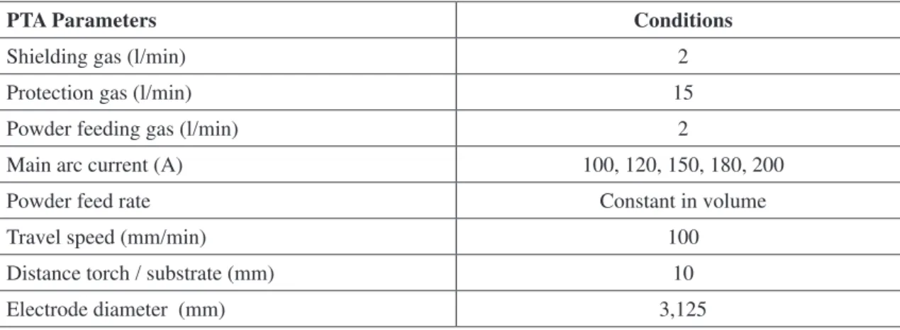
Atomized CoCrWC alloy with particle size range between 90 and 150 μm was deposited on AISI 316L stainless steel plates 100 x 100 x 12,5 mm, without substrate pre-heating or torch oscillation, Table 1. Production of coatings involved deposition current changing as shown on Table 2.
Powder feeding gas (l/min) 2
Main arc current (A) 100, 120, 150, 180, 200
Powder feed rate Constant in volume
Travel speed (mm/min) 100
Distance torch / substrate (mm) 10
Electrode diameter (mm) 3,125
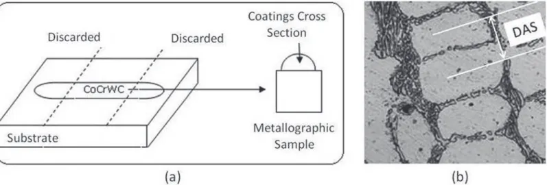
Visual analysis was performed for coatings integrity and track geometry determined according Figure 1. Dilution was measured by area ratio between melted substrate and coating total area on transverse cross section for single tracks. Dendrite arm spacing (DAS) and volume fraction of carbides were deter-mined as an average of ive measurements on coatings cross sec-tions for each deposition condition through Olympus Soft Imag-ing Solutions ® software, Figure 2. Samples were prepared by
standard metallographic procedures and microstructure analysis performed on the middle of the cross section of coatings. Micro-structure was assessed by Laser confocal and scanning electron microscopy. Phase evaluation by X-ray diffraction analysis us-ing KaCu from 20 to 120º for 1 s for each exposure channel was done.
Figure 1.Schematic showing tracks geometry measurement: Wettability angle (Q), reinforcement thickness (t) and width
(w).
on performance of coatings by the wear mass loss rate. Square pins of 4 x 4 mm were machined out from coatings and worn out against Al2O3 paper #220 with 0,5 kgf load and 1,5 m/s tangen-tial speed. Pins were weighted before test and after each 125 m sliding distance at room temperature.
3. Results and Discussion
3.1. Coatings Integrity, Dilution and Track Geometry
Visual inspection revealed sound coatings with no cracks or porosity. Coatings dilution from 11,8 to 55,6 % was obtained and just deposition with 100 A current itted within the expected 5 to 15 % range mentioned for PTA coatings, Table 3 [8, 9].
Geometry of single tracks indicated the wettability angle varied between 52,1 and 27,0 0, decreasing as the current
increased. Higher deposition current induced higher width (ranging: 9,5 – 15,3 mm) and lower reinforcement thickness (ranging: 2,6 – 3,7 mm), Table 3.
3.2. Processing Effect on Microstructure
The consequences of PTA hardfacing with different deposition current were assessed by the microstructure
Figure 2. Schematic showing: (a) Cross section metallographic samples and (b) DAS measurement.
Table 3. Geometry and dilution of single track deposits.
CoCrWC Alloy – PTA Coatings
Substrate Parameter
Deposition Current (A)
100 120 150 180 200
AISI 316L
Dilution (%) 11,8 21,7 35,9 49,5 56,6
Wettability Angle, Q (0) 52,1 42,0 40,7 38,6 27,0
Thickness, t (mm) 3,7 3,4 2,8 2,7 2,6
Width, W (mm) 9,5 11,9 13,5 14,9 15,3
description of CoCrWC alloy coatings. Dendrite arm spacing (DAS), formed phases, morphology and volume fraction were evaluated in the as-deposited condition.
Figure 3. Laser Confocal microstructure of CoCrWC alloy coatings.
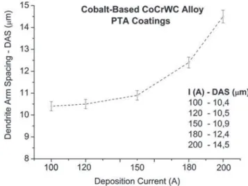
Figure 4. Dendrite Arm Spacing (DAS) for CoCrWC alloy coatings.
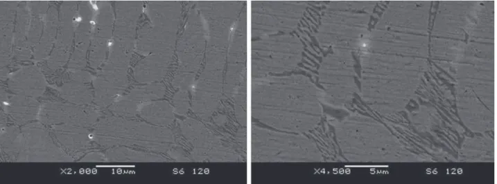
Figure 6. Microstructure of CoCrWC alloy coatings. I (A): 120.
Figure 7. Microstructure of CoCrWC alloy coatings. I (A): 150.
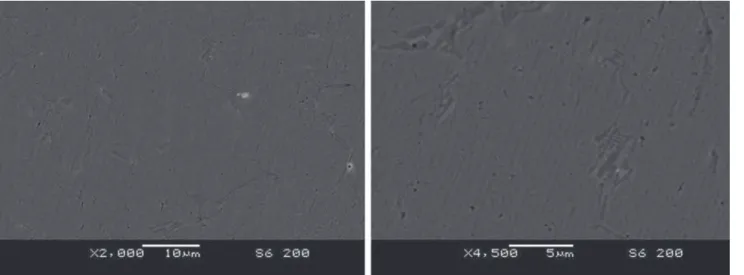
Figure 9. Microstructure of CoCrWC alloy coatings. I (A): 200.
Two different carbides were formed on coatings: M7C3 type (where M: Chromium) on the eutectic lamellar structure and dispersed M2C blocky (where M: Tungsten), as previously reported by literature, Figure 10 [11, 12].
Figure 10. X-ray diffraction analysis on CoCrWC alloy coatings.
Phase quantifying conirmed that the increase on deposition current induces signiicant reduction on the volume fraction of hard phases, as a consequence of higher dilution (or higher iron content), Figure 11 and Figure 12. It leaded to lower Chromium, Tungsten and Carbon content on chemical composition of alloy coatings, and induced carbides fraction decrease. The total carbides fraction decreased 84 % when increasing the deposition current from 100 to 200 A, but the most signiicant reduction was obtained for the current range from 100 to 150 A, which induced 63 % reduction on Chromium and 56 % on Tungsten carbides. The amount of carbides participating of the microstructure is in agreement to the reported by literature for the lower dilution obtained [12].
Figure 11. Chromium lamellar eutectic carbides fraction.
The analysis of microstructure using energy dispersive spectrometry (EDS) showed the Cobalt solid solution dendrites are composed mainly by Cobalt, Chromium and Iron from substrate. The chemical distribution showed concentration of Tungsten on white blocky carbides (BC) and Chromium on lamellar eutectic carbides (LEC). As the Iron content increased, lower alloying was observed on Cobalt solid solution dendrites (Co SS), Table 4.
Table 4. Distribution of main elements on microstructure by energy dispersive spectrometry (EDS).
Current (A)
Region Chemical Composition - Wt%
Co Cr W Fe Si
Atomized
Alloy Bal. 27,9 4,7 1,8 1,2
100
Co SS Bal. 23,7 1,1 8,0 0,9
LEC Bal. 42,2 7,1 6,6
---BC Bal. 21,2 27,4 4,8
---120
Co SS Bal. 22,6 0,9 15,8 0,7
LEC Bal. 40,1 4,9 11,5
---BC Bal. 20,9 31,1 6,8
---150
Co SS Bal. 18,6 0,8 21,7 0,9
LEC Bal. 41,1 4,4 17,4
---BC Bal. 18,5 24,8 14,4
---180
Co SS Bal. 18,1 0,6 32,6 0,5
LEC Bal. 42,6 6,4 24,5
---BC Bal. 17,2 16,7 19,3
---200
Co SS Bal. 17,5 0,5 38,9 0,6
LEC Bal. 42,3 2,8 22,3
---BC Bal. 15,8 13,9 26,6
---Co SS – ---Cobalt Solid Solution LEC – Lamellar Eutectic Carbides BC – White Blocky Carbides
3.3. Coatings Hardness and Wear Behavior
Further assessment of the effect of deposition current on coatings features was analyzed thru the hardness and wear behavior. Aiming to identify the inluence of PTA deposition on the response of each coating to abrasive sliding wear, coatings were evaluated with a constant set of testing parameters.
Coatings showed hardness dependence to the deposition current, associated to the heat input on welding. It induced microstructure coarsening (higher DAS) and dilution increase. The dilution inluenced the hardness by reduction on Cobalt solid solution alloying and volume fraction of hard phases (carbides).
Measured hardness of deposition with 100 and 200 A current were 500 HV and 310 HV respectively, representing a reduction of 38 %, according literature predictions, concerning the inluence of dilution on properties, Figure 13 [10, 13]. Despite the large variation observed as deposition current was altered,
coatings presented uniform hardness throughout each coating.
Figure 13. Hardness depth proiles of CoCrWC alloy coatings.
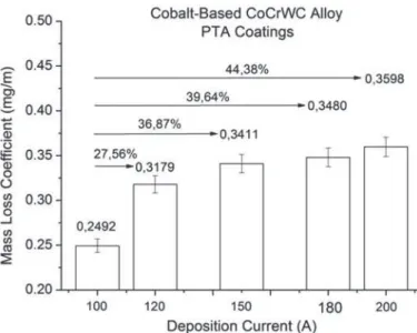
The microstructure and hardness changing obtained as a consequence of processing with higher current, induced increase on mass loss rate, Figure 14. Linear correlation between sliding distance and mass loss and a near constant wear rate were measured with increasing sliding distance, in agreement to previous results [6].
The chemical composition of the CoCrWC alloy developed on coatings inluenced the mass loss rate. Deposits processed with 100 A deposition current showed the lower wear rate (0,2492 mg/m). As dilution increased, the mass loss coeficient increased up to 0,3598 mg/m for 200 A reaching 44,38% increment, Figure 15. Better behavior can be related to the higher hardness dictated by the volume fraction of the hard interdendrictic eutectic and blocky carbides, solid solution alloying and reinement degree [10].
As the Co-based alloy experienced Iron content increase, the solidiication formed large areas of Cobalt solid solution dendrites (the lower hardness phase of alloy coatings) which leaded to poor wear performance. At the same time, the low
Figure 15. Wear mass loss rate coeficient for CoCrWC alloy coatings.
4. Final Remarks
This study analyzed the effect of PTA deposition current on CoCrWC alloy coatings features and included the analysis of soundness and track geometry correlating microstructure to properties and performance. The main contributions can be summarized as follows:
- Sound coatings were obtained for all conditions and, increasing the deposition current, better weldability of the CoCrWC alloy on AISI 316L was obtained.
- The analysis of deposition current of CoCrWC alloy hardfacing showed important effect on reinement degree, solid solution alloying and volume fraction of hard phases. So, the heat input altered the cooling rate on solidiication changing the DAS and, the dilution, the amount of main alloying elements.
- Dilution increased with deposition current and, as a consequence, the higher Iron content leaded to higher volume of Cobalt solid solution areas, reducing the volume of hard phases. So, hardness depended on microstructure reinement and amount of alloying elements, the latter dictating the solid solution and second phase hardening effects.
- Wear behavior of coatings was dictated by ratio between Cobalt solid solution and carbides fraction, which was signiicantly increased with the deposition current. Once Cobalt solid solution is worn out preferentially, important increase on wear mass loss rate was observed for coatings deposited with higher deposition current.
- Higher deposition current induced hardness and wear
[2] LEMAIRE, E., LE CALVAR, M. Evidence of tribocorrosion wear in pressurized water reactors. Wear. v.249, 338-344, 2003. [3] SCHEID, A., SCHREINER, W. H., D’OLIVEIRA, A. S. C. M. Effect of temperature on the reactivity between a CoCrMoSi alloy and 55 wt% AlZn baths. Corrosion Science. V. 55, 363-367, 2012.
[4] ZHANG, K., BATTISTON, L. Friction and wear characterization of some Cobalt- and iron-based superalloys in zinc alloys baths. Wear.v. 252: 332-344, 2002.
[5] ZHANG, K. Effects of test conditions on the tribological behavior of a journal bearing in molten zinc. Wear. v. 259, 1248-1253, 2005.
[6] SCHEID, A., D’OLIVEIRA, A. S. C. M. Effect of temperature and reactivity of molten 55Al–Zn alloy on Co based alloy coatings. Materials Science and Technology. V. 26, 1487-1493, 2010.
[7] GONÇALVES, R. H., DUTRA, J. C. PTA-P Process - A Literature Review as Basis for Innovations. Part 1 of 2: Constructive Elements. Soldagem & Inspeção. v. 17, 076 – 085, 2013.
[8] DAVIS, J. R. Hardfacing, weld cladding and dissimilar metal joining. In: ASM Handbook 6: Welding, Brazing and Soldering. 10th ed. ASM International; 1993. p. 1967-1996.
[9] D’OLIVEIRA, A. S. C. M., VILAR, R., FEDER, C. G. High temperature behaviour of plasma transferred arc and laser Co-based alloy coatings. Applied Surface Science. v. 201, 154 -160, 2002.
[10] ANTOSZCZYSZYN, T. J., PAES, R. M. G., D´OLIVEIRA, A. S. C. M., SCHEID, A. Impact of dilution on the Microstructure and Properties of Ni-Based 625 Alloy Coatings. Soldagem e Inspeção. v. 02, 134-144, 2014.
[11] RAFAEL, G., HENKE, S. L., D´OLIVEIRA, A. S. C. M. Microstructural control of Co-based PTA coatings. Materials Research (São Carlos. Impresso).v. 15, 796–800, 2012.
[12] KLASTROM, D., WU, J. Metallography and Microstructures of Cobalt and Cobalt Alloys. In: ASM Handbook, Metallography and Microstructures. 10th ed. ASM International; 2004. p. 1813 – 1830.