REM: R. Esc. Minas, Ouro Preto, 66(2), 227-232, abr. jun. | 2013 227
Resumo
Esse artigo apresenta os resultados de um estudo experimental que visa a avaliar o efeito do desgaste supericial sobre as propriedades de atrito de interfaces geossintéticas constituídas por geomembranas. Os ensaios foram realizados em equipamento de plano inclinado e os resultados demonstram as diferentes sensibilidades das interfaces, testadas ao processo de desgaste. Para os tipos particulares de interfaces consideradas no programa experimental, constatou-se que o desgaste supericial pode aumentar, diminuir ou manter as propriedades originais de atrito da interface geossintética, repercutindo, diretamente, sobre a estabilidade desta sob condição de serviço.
Palavras-chave: Interface geossintética, desgaste supericial, atrito, geomembrana.
Abstract
This article presents the results of an experimental study which aimed to evaluate the effect of surface wear on the friction properties of geosynthetic interfaces constituted of geomembranes and geospacers. The tests were performed in ramp test device, and the results showed the different sensitivities of the interfaces to the wear process. For the particular types of interfaces considered in the experiment, the surface wear can increase, decrease or maintain the original friction properties of the geosynthetic interface, with direct effects on the stability under service condition.
Keywords: Geosynthetic interface, surface wear, friction, geomembrane, geospacer.
Wear resistance of geosynthetic
interfaces constituted by
geomembranes and geospacers
Resistência ao desgaste de interfaces geossintéticas
constituídas por geomembranas e geoespaçadores
Heraldo Nunes Pitanga
Professor adjunto, DTECH,
Universidade Federal de São João del Rei, Campus Alto Paropeba,
Ouro Branco-MG, Brasil. [email protected]
Orencio Monje Vilar
Professor Titular,
Escola de Engenharia de São Carlos (EESC), Universidade de São Paulo,
São Carlos-SP, Brasil. [email protected]
Jean-Pierre Gourc
Professor titular, LTHE,
Université Joseph Fourier (Grenoble I), Grenoble, França.
Engenharia Civil
Civil Engineering
1. Introduction
Geosynthetics is a generic name of a set of industrial polymeric products, whose properties contribute to the im-provement of civil engineering works, playing one or more of the following func-tions: strengthening, iltration, drainage, protection, separation, waterprooing and control of surface erosion (Koerner, 1998). The advent of geosynthetics revolutionized
several aspects of project and construction of civil engineering works and, in particu-lar, of works for environmental protec-tion. In these works, almost all types of geosynthetics can be employed, fulilling their typical functions (Vilar, 2003).
developed to provide more protection to the environment in order to minimize the percolation of contaminant liquids and gases from the degradation of residuals generated by human activities, preventing them to reach the air, soil and groundwa-ter. This is a two dimensional product of very low permeability, predominantly composed of asphalts, elastomers or plas-tomers, used for low control and separa-tion, under service conditions.
In general, the geomembranes are not employed separately; they are fre-quently in contact with other geosyn-thetics or natural materials, constituting a composite coating system. When in contact with other material, a geomem-brane constitutes an interface and, under service conditions, the properties of one or both components of this interface can be altered. In this context, the wear is the process which implies in the alteration of the surface characteristics of a geosynthet-ics when it interacts with other material or surface.
In civil works aiming to protect the environment (landfill sites, ponds containment and treatment of industrial waste) interfaces which contemplate geo-membranes are generally arranged on inclined surfaces to ensure that the volume of stored tailings occupies the smallest area possible (Sharma and Lewis, 1994). Therefore, there is a natural tendency for the components of an interface to slide in
relation to each other, but this tendency will be resisted by the interface friction between the materials. However, as this displacement is almost always inevitable, the promoted surface wear can alter deleteriously the frictional characteristics of the interface, contributing thus to a gradual instability increase of the coat-ing system. Additionally, the processes of expansion and contraction induced by the variation in temperature, the processes of damage of geosynthetic surfaces dur-ing the installation of the product under construction and during the other stages of the constructive process can enhance the degree of surface wear of interfaces constituted by such polymeric materials.
Thus, the knowledge of the sensitiv-ity of a geosynthetic interface to the wear mechanism triggered at its installation in civil engineering works is an important design issue that should be considered by the manufacturers of geosynthetics, by the project designers and by the executors of the work. The differences among the respective hardness of materials based on PVC (Polyvinyl Chloride), PE (Polyethyl-ene), HDPE (High-Density Polyethyl(Polyethyl-ene), LDPE (Low-Density Polyethylene) and VLDPE (Very-Low-Density Polyethylene) and how these differences can affect the behavior of these materials are well docu-mented and reinforce the importance to study the susceptibility of geosynthetic sys-tems to the wear process under conditions
similar to service conditions. In addition to the material hardness conveyed by the polymeric constitution, the surface rough-ness (smooth or rough surface), the nature of contact material (natural or synthetic) and the level of normal stress acting on the interface are also factors governing the mechanism of interface wear (Dove, 1996; Dove et al., 1997; Lee et al., 1998; Zettler et al., 2000; Frost and Lee, 2001; Frost et al., 2002).
In this context, the goal of this experimental study was to characterize the wear resistance of geosynthetic inter-faces, considering three different smooth geomembranes of distinct polymeric con-stitutions in contact with a second geosyn-thetic material (geospacer). The tests were carried out employing a ramp test device, which allows reproducing on the studied interface the low normal stresses found in conditions of service of the coating systems of environmental works constituted by these materials. Several studies drawing a parallel between ramp test device and shear box shown that the ramp test is a more appropriate device for the charac-terization of geosynthetic friction under normal stress lower than 10 kPa, which is typical of capping systems. In contrast, the direct shear box performs well under higher normal stresses as is common in bottom liners of landill (Reyes-Ramirez and Gourc, 2003; Palmeira, 2009).
2. Materials
The materials employed in the research intended to characterize the wear resistance of geosynthetic interfaces constituted of geomembranes are listed in the Table 1. These materials included smooth polymeric geomembranes (GM) of High-Density Polyethylene (HDPE),
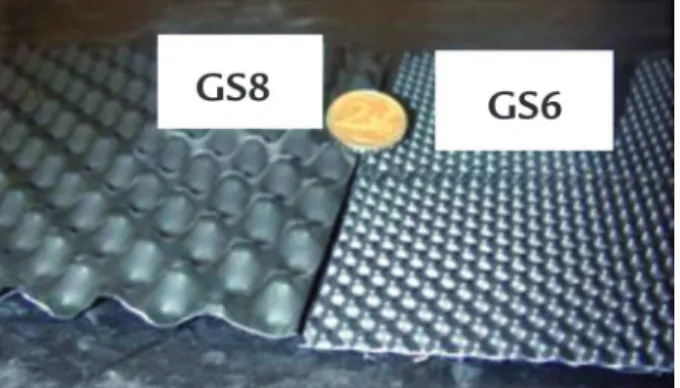
Polyvinyl Chloride (PVC) and Polypropyl-ene (PP) and a geosynthetic product based on High-Density Polyethylene (HDPE), called geospacer (GS), which is frequently employed together with geomembranes in works for environmental protection, having the essential function of drainage
(Figure 1). The geomembranes GMHDPEa and GMHDPEb have essentially the same surface aspect and the same polymeric composition, however from different manufactures. Two geospacers of differ-ent thickness and surface structures were employed (GS8 and GS6).
Table 1
Main characteristics of geosynthetics employed in the research on the wear resistance of geosynthetic interfaces.
Geosynthetic Polymer nature Notation Thickness (mm)
Geomembrane
HDPE GMHDPEa 1.5
GMHDPEb 1.5
PVC GMPVC 1
PP GMPP 1
Geospacer HDPE GS8 8
GS6 6
3. Methods
Ramp test device
The setup for the tests of the wear resistance of geosynthetic interfaces is
presented in the Figure 2, which con-templates the characteristic base system
REM: R. Esc. Minas, Ouro Preto, 66(2), 227-232, abr. jun. | 2013 229 Figure 1
Geospacers employed in the research.
elements (Figure 2C):
a. A movable metal plate (A), which allows to receive the test sample of the upper geosynthetic (C), which is bonded on a wood plate (B).
b. A wood plate (B) with dimensions of 18 cm (in the direction of sliding) by 70 cm (in the direction transversal to the sliding).
c. Metal plates (D) whose dimensions are similar to the wood plate (18 x 70 cm2)
and serve as overload.
The initial normal stress (sup-port plane at horizontal position) corresponds to so=P/A, where P is the total weight applied on the contact
surface (including the support wood plate to which the upper geosynthetic is bonded), and A is the contact area (18 x 70 cm2). The initial normal stress
is obtained with the aid of metal plates (Figure 2C, D) attached to the movable metal plate (Figure 2C, A) with screws. The lower geosynthetic sample is ixed to the support plane of the equipment (80 cm width by 130 cm length) and anchored on the top through a securing device. The movable plate is equipped with side guides (spherical contacts), which allow a rectilinear sliding, non-diverted regarding the sliding direction (Figure 2C, A). This guidance system
is assumed without lateral frictions, enabling thus a total transference of the normal stress to the geosynthetic interface. The inclined plane device is constituted of a rigid base whose lower extremity tends to rotate around a hori-zontal axis, resulting in the inclination of the plane. Thus, at the beginning of the test, the inclined plane device is at horizontal position, and as the plane becomes inclined (at an angular veloc-ity of 3°/minute), the displacements of the movable plate with the geospacer [d(t)] and the angle of inclination of the rigid base [b(t)] are recorded by the data acquisition system.
Figure 2 Setup of the ramp test device for performing wear resistance tests of geosynthetic interfaces: (A) General scheme of the ramp test device. (B) Ramp test device with movable plate system. (C) Scheme of the upper movable plate system.
Wear resistance tests
In this analysis, it was tested sev-eral times the same sample of the upper geosynthetic component of the interface. In every test (numbered from j= 1 to n), the upper geosynthetic slides until a given displacement, resulting in a cumulative wear on its surface arising from the inter-action with the lower geosynthetic upon which the upper geosynthetic slides. The
tangential displacement during a given test (d) is identiied with the purpose to differentiate it from the total tangential displacement (D) suffered by the sample throughout the series of tests, with D0
representing the cumulative displace-ment at the beginning of the test and Df
the displacement at the end (for test 1:
D0 = 0 mm, Df =300 mm, for instance).
It was considered an initial normal stress of so=5 kPa. Besides, it was exclusively considered the cumulative displacement on the surface of the upper geosynthetic (the one which slides). Thus, at every test cycle, the upper geosynthetic (bonded to the wood plate) was maintained, while the lower geosynthetic (ixed to the sup-port plane and upon which the upper
A
B
geosynthetic slides) was replaced by a new virgin sample.
In this research, the surface wear
resistance imposed to the geosynthetic interface was indirectly assessed by the variation in the sliding angle blim of the
upper geosynthetic component of this interface by the end of each wear cycle, as illustrated in the Figure 3.
Figure 3
Displacement curves d as a function of the inclination of the base plane b for each wear cycle imposed to the interface.
4. Results and discussion
The Figure 4 and the Table 2 show the results for the wear resistance tests corresponding to the geomem-brane interfaces of HDPE, geospacer-geomembrane of PP and geospacer-geo-membrane of PVC. In these tests, a same sample of geospacer was slid several times upon virgin geomembrane samples. Every wear cycle [sequences (1), (2) and (3)] and the cumulative displacement on the upper geosynthetic surface at the end of that cycle (in mm) were identiied.
For the interfaces between the re-spective geospacers (GS8 and GS6) and the geomembrane of HDPE, the curves
d(b) were moved to the right at the end of every cycle, showing that this increased the friction between the interface components, being necessary, therefore, higher slopes to promote the geospacer sliding upon the geomembrane (blim1< blim2<blim3). This was contrary to the presented by the interface between the geospacer GS6 and the
geo-membrane of PP, whose curves d(b) were displaced to the left at the end of every wear cycle, evidencing a reduced friction in the interface contact as increased the wearing imposed by the geomembrane to the geospacer surface. In this case, the sys-tem required increasingly smaller slopes for the sliding of the upper geosynthetic on the lower (blim1>blim2>blim3).
In the case of the interface between the geospacer and the geomembrane of PVC, there was essentially no change in its behavior given increased surface wear on the geospacer. This was evidenced by the overlap of curves d(b). Thus, the friction mobilized during the upper geosynthetic sliding on this geomembrane was similar for the performed wear cycles (blim ap-proximately constant).
A second set of tests considered the geomembrane as element sliding on the geospacer leaned on the base plane of the inclined plane device
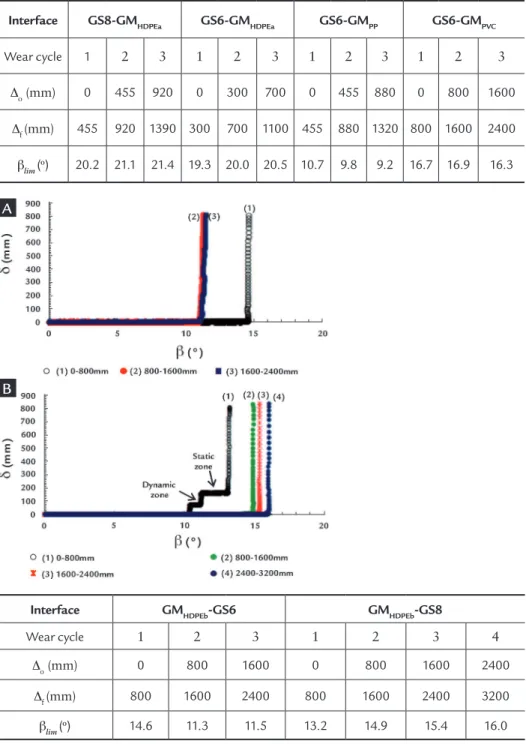
(geomembrane-geospacer interface). This is a setup inverse to that previously tested, since the relative position among the components of the interface had been changed. The Figure 5 and the Table 3 show the results of the wear resistance tests on the interfaces of this new setup.
In these tests, a same sample of geomembrane was slid several times upon virgin samples of geospacer. Every wear cycle [sequences (1), (2), (3), (4)] and the cumulative displacement on the upper geosynthetic surface at the end of that cycle (in mm) were identiied. Distinct responses to the process of surface wear were presented by these conigurations. For the GMPEADb-GS6 interface, it was observed a reduced friction of interface at the end of the second cycle of surface wear (blim2 < blim1), being this cycle responsible for irreversible changes on the geomem-brane surface, once the subsequent cycle does not alter the resistant properties of
Figure 4
Results of wear resistance tests of geospacer-geomembrane interfaces: (A) GS8-GMHDPEa interface.
(B) GS6-GMHDPEa interface. (C) GS6-GMPP interface. (D) GS6-GMPVC interface.
Cycle (3) Cycle (2) Cycle (1)
blim3 blim2 blim1
b
d
A B
REM: R. Esc. Minas, Ouro Preto, 66(2), 227-232, abr. jun. | 2013 231
Interface GS8-GMHDPEa GS6-GMHDPEa GS6-GMPP GS6-GMPVC
Wear cycle 1 2 3 1 2 3 1 2 3 1 2 3
Do (mm) 0 455 920 0 300 700 0 455 880 0 800 1600
Df (mm) 455 920 1390 300 700 1100 455 880 1320 800 1600 2400
blim (
o) 20.2 21.1 21.4 19.3 20.0 20.5 10.7 9.8 9.2 16.7 16.9 16.3
Table 2 Data extracted from wear resistance tests for the
geospacer-geomembrane interfaces.
this interface (blim2 ≈blim3). The GMPEADb -GS8 interface, in turn, presented during the irst wear cycle an atypical behavior characterized by a phenomenon called “stick-slip”. This phenomenon can be explained by the occurrence of successive textural modiications produced by the surface wear, which lead to change the friction properties of this interface, gen-erating successive zones of static behavior (levels of constant displacement with dd/ db→0), followed by zones of dynamic behavior (ranges of sudden increase in displacement with dd/db→8). The subse-quent wear cycles not only increased the interface friction, but also eliminated the tendency to the “stick-slip” as previously identiied, conducting the interface to a sudden sliding. This aspect enhanced the
sensitivity of the geosynthetic interface to the wear process.
With the set of experimental results, previously presented and exclusively considering the geosynthetic materials employed herein, it was possible to notice that:
• The sensitivity of geosynthetic inter-faces to the surface wear process was closely dependent on the particular type of geomembrane component of the interface: in contact with the geospacer of 6mm (GS6), the geomembrane of HDPE increased the interface properties of friction, while the interface of this geospacer together with the geomembrane of polypropylene (PP) had its friction reduced with the surface wear; in
turn, the surface wear imposed to the geospacer surface by the PVC geomembrane did not modify the magnitude of the friction mobilized on the interface.
• This sensitivity was dependent on the relative position among the geosyn-thetic elements components of the interface: when the geospacer GS6 was slid upon the HDPE geomem-brane, being supericially worn by the geomembrane, the friction of interface increased with the wear process; when the geomembrane of HDPE was slid upon the geospacer GS6, the interface friction was reduced.
• This sensitivity was dependent on the structure of the geosynthetic elements components of the interface: when the Figure 5
Results of wear resistance tests of geomembrane-geospacer interfaces: (A) GMHDPEb-GS6 interface. (B) GMHDPEb-GS8 interface.
Table 3 Data extracted from wear resistance tests
of geomembrane-geospacer interfaces.
Interface GMHDPEb-GS6 GMHDPEb-GS8
Wear cycle 1 2 3 1 2 3 4
Do (mm) 0 800 1600 0 800 1600 2400
Df (mm) 800 1600 2400 800 1600 2400 3200
blim (
o) 14.6 11.3 11.5 13.2 14.9 15.4 16.0
A
HDPE geomembrane was slid upon the geospacer GS6, the friction of interface decreased with the surface wear; when this geomembrane was slid upon the geospacer of 8mm (GS8),
the interface friction was enhanced by this process.
• According to the particular type of geomembrane component of an inter-face, the form of rupture or of sliding
of an interface subjected to the surface wear can be drastically changed (slid-ing “stick-slip” transformed into sud-den sliding, for instance).
5. C
onclusions
Geosynthetic interfaces are sensitive to the surface wear process. This sensitiv-ity has consequences in friction properties, and it may increase or decrease their stabil-ity under the conditions of service typical to which when subjected in works. The damaging effect due to the relative tangen-tial displacement can increase or decrease the interface friction, depending of the pair of associated geosynthetics. The particular type of geomembrane component of a geosynthetic interface plays an important role in the response of this interface to the
surface wear process. Additional factors such as the relative position among the elements of the interface and the structure of these elements also interfere with the mechanism of wear resistance. Conditions of deployment of the geosynthetic lining systems on slopes, initial wrinkles, and in-dividual conditions of tensile mobilization of the geosynthetics might induce large relative displacements at the interfaces. For these large displacements, which are not considered in the standard interpretation, the alteration of the geosynthetic surface
by abrasion can also signiicantly modify the limit friction angle. The previous knowledge of this sensitivity is, therefore, an important issue of design, which must be considered by the manufacturers of geosynthetics, by the project designers and by the executors of civil works that involve the application of these polymeric materials. Such knowledge can provide a quantitative basis useful for the develop-ment of products and for the choice of most appropriate geosynthetic interfaces to the surface wear predicted in work.
6. Acknowledgements
The authors thank to the partner-ship Capes-Cofecub for the financial
support and FAPEMIG for supporting the article.
7. References
DOVE, J.E. Particle-geomembrane interface strength behavior as inluenced by surface topography. Atlanta, Georgia, USA: School of Civil and Environmental Engineering, Georgia Institute of Technology, 1996. 323 p. (Ph.D. Dissertation). DOVE, J.E., FROST, J.D., HAN, J., BACHUS, R.C. The inluence of geomembrane
surface roughness on interface strength. In: GEOSYNTHETICS‘97, Proceedings… IFAI, v. 2, Long Beach, California, USA, March 1997, p. 863. 1997.
FROST, J.D., LEE, S.W. Microscale study of geomembrane-geotextile interactions. Geosynthetics International, v. 8, n. 6, p. 577, 2001.
FROST, J.D., ZETTLER, T.E., DEJONG, J.T., LEE, S.W., KAGBO, S. Strain induced changes in geomembrane surface topography. Geosynthetics International, v. 9, n.1, p. 21, 2002.
KOERNER, R.M. Designing with Geosynthetics. 4th edition. New Jersey: Prentice
Hall Inc., Upper Saddle River, 1998.
LEE, S.W., FROST, J.D., RIGHTER, G.K. The inluence of geomembrane surface roughness on geomembrane-geotextile interface strength. In: INTERNATIONAL CONFERENCE ON GEOSYNTHETICS, IFAI, 6. Proceedings..., v. 1, Atlanta, Georgia, USA, April 1998, p. 433, 1998.
PALMEIRA, E. M. Soil-geosynthetic interaction: modeling and analysis. Geotextiles and Geomembranes, v. 27, n. 5, p. 368, 2009.
REYES-RAMIREZ, R., GOURC, J. P. Use of the inclined plane test in measuring geosynthetic interface friction relationship. Geosynthetics International, v. 10, n.5, p. 165, 2003.
SHARMA, H.D., LEWIS, S.P. Waste containment system, waste stabilization and landills: design and evaluation. New York: John Wiley & Sons, 1994.
VILAR, O.M. Geossintéticos em aplicações ambientais. In: SIMPÓSIO BRASILEIRO DE GEOSSINTÉTICOS - GEOSSINTÉTICOS’2003, 4. Porto Alegre-RS, p. 203, 2003. ZETTLER, T.E., FROST, J.D., DEJONG, J.T. Shear-Induced Changes in Smooth
HDPE Geomembrane Surface Topography. Geosynthetics International, v. 7, n.3, p. 243, 2000.