J. of the Braz. Soc. of Mech. Sci. & Eng. Copyright © 2008 by ABCM July-September 2008, Vol. XXX, No. 3 / 221
S. E. Oraby
A. M. Alaskari
[email protected] College of Technological Studies, PAAET P.O. 42325 70654 Shuwaikh, Kuwait
Surface Topography Assessment
Techniques based on an in-Process
Monitoring Approach of Tool Wear
and Cutting Force Signature
One of the most influential sources in machining affecting surface roughness is the instantaneous state of tool edge. The main objective of the current work is to relate the in-process immeasurable cutting edge deformation and surface roughness to a more reliable easy-to-measure force signals using a robust non-linear time-dependent modeling regression techniques. Correlation between wear propagation and roughness variation is developed throughout the different edge lifetimes. The surface roughness is further evaluated in the light of the variation in both the static and the dynamic force signals. Consistent correlation is found between surface roughness variation and tool wear progress within its initial and constant regions. At the first few seconds of cutting, expected and well known trend of the effect of the cutting parameters is observed. Surface roughness is positively influenced by the level of the feed rate and negatively by the cutting speed. As cutting continues, roughness is affected, to different extents, by the rather localized wear modes either on the tool nose or on its flank areas. Moreover, it seems that roughness varies as wear attitude transfers from one mode to another and, in general, it is shown that it is improved as wear increases but with possible corresponding workpart dimensional inaccuracy. The dynamic force signals are found reasonably sensitive to simulate either the progressive or the random modes of tool edge deformation. While the frictional force components, feeding and radial, are found informative regarding progressive wear modes, the vertical (power) components is found more representative carrier to system instability resulting from the edge’s random deformation.
Keywords: dynamic force signals; surface roughness (finish); tool wear and deformation; tool wear modes (nose, flank)
Introduction
1
The ultimate objective of a manufacturing process is to come up with a product with acceptable features of safety, quality and cost. Both safety and quality requirements are the main elements of what is called “surface integrity”. Surface integrity has two important parts. The first is surface texture, which governs principally surface roughness, essentially is a measure of surface topography (surface finish and dimensional accuracy). The second is surface metallurgy which is a study of the nature of the surface layer produced in machining (subsurface damage, residual stresses, and surface work hardening) (Machining Data Handbook Machinability Data, 1972).
Ideally when the cutting edge is still intact, surface roughness of a machined workpart is predominantly principally affected by the operating cutting parameters, especially feed rate, as well as the edge configuration. Once wear scars develops on the edge, many other influencing factors are introduced and surface quality is no longer of ideal or deterministic nature. It is thought that tool wear is one of the main sources of process variability since it excites and escalates friction and forces. Edge deformation may be either progressive or random. Progressive wear is inevitable as the tool is in intimate contact with the abrasive inclusions of the workpart material. Edge is categorized, according to the wear mode, into nose, flank and notch regions. Additionally, a crater develops on the tool face as the strain-hardened, underside, chip surface slides out generating a crater that increases in both depth and width as time passes. However, cratering of coated carbide inserts is usually less likely to occur at practical moderate cutting speed-feed rate ranges where the controlling factor for tool life is only the flank and the nose wear modes (Lim et. al. 1999).
Paper accepted April, 2008. Technical Editor: Glauco A. de P. Caurin.
In spite of their functionally undesired impact, edge wear and deformation are still difficult and costly to monitor on-line during the unmanned automated manufacturing processes. Conventional direct techniques to assess edge wear and life are not always accurate due to the common process variability (Oraby 1995a). Therefore, indirect methods are often instead employed to in-process monitoring using one or more of the measurable machining responses. Among candidates responses to indirectly monitor edge deformation are: the static and the dynamic force signals (Oraby 1995b, Youn & Young 2001, Oraby and Hayhurst 2004, Oraby et. al. 2005); the cutting temperature (Zehender et. al. 2000, Dawson 2002); the consumed motor power (Shao et al. 2004); the system dynamic characteristics and the acoustic emission (Lin & Chang 1998, Kamarthi et. al. 2000, XiaoQi et. al. 2001, Liang et. al. 2002) and even optically (Choudhury et al. 2001).
Moreover, to implement any of the aforementioned indirect techniques in adaptive control system to monitor and control tool performance, including tool state and surface quality, it is necessary to use the appropriate mathematical interface which, in turns, usually requires modelling of a wide spectrum of operating conditions. Among the promising mathematical optimization approach are the neural network analysis and genetic algorithms (Fang et. al. 1997, Azouzi & Guillet 1997, Suresh et. al. 2002, Rao & Srikant 2004, Ezugwu et al 2005).
In conclusion, in order to come up with a credible roughness wear-based detection approach, some essential aspects should be carefully evaluated. First, the possible correlation between each of edge deformation modes and the corresponding variation in roughness should be accurately formulated. Second, the immeasurable edge deformation should be related to the variation in the easy-to-measure-and-manipulate sensitive force signals. Finally, only the most informative variations in the force signals should be accurately isolated and processed.
interrelationship bearing in mind the establishment of an online tool state approach for the possible implementation in the adaptive control and other advanced manufacturing systems. The effects of different tool edge progressive wear modes (wear of nose, flank, and notch) on the roughness are investigated. The effects of the cutting parameters (cutting speed, feed rate and depth of cut) are considered, and the possible nonlinearity is taken into account. Experimental data are used to develop adequate and significant nonlinear time-varying models.
Experimental Set Up and Data Collection Procedures
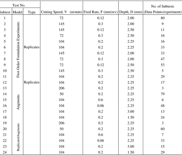
To obtain a statistically significant and well conditioned data over a specified cutting parameters domain, it is necessary to design the experiments accordingly. The unplanned or happenstance data arising from non-designed experiments might not have the desired properties needed for regression analysis, and hence cause ambiguities during model building (Balakrishnan & DeVries 1983). There are many methods for design of the experiments such as factorial design, fractional factorial design, central composite design, and non-central composite design. The central composite design CCD is the most appropriate to the purpose of metal cutting modeling (Draper & Smith 1967 & Hines and Montgomery 1982). Moreover, (CCD) experimental design technique is used to design the experiments so as to save time, tools and specimens over the conventional one-variable-in-turn approach. For each of the cutting parameters (cutting speed, feed rate and depth of cut), three levels (low-medium-high) are selected for the first order formulation. To account for the possible non-linearity and interaction involved in the data, two augments are added (lowest & highest). Center and augment experiments are replicated to distinguish between lack-of-fit and experimental error. The CCD experimental design procedures has led to 24 constant-variables as indicated in Table 1.
The employed cutting tools are multi coated carbide inserts [Sandvik GC435] with standard SPUN 10 03 12 designations, with nose radius of 1.2 mm. Coating layers are: TiN (1 µm), Al2O3 (3µm), and TiC (3µm). This type is ideal for steel cutting mainly within ISO P35 domain which includes steel, steel casting, long chipping malleable iron and stainless steel. The workpiece material is a medium carbon steel BS 970 080M40 (AISI 1040 or En8) with chemical composition 0.435% C, 0.69% Mn, and 0.2% Si. Mechanical and other relevant properties are: Brinell hardness 205, ultimate tensile strength 620MPa, yield strength 415 MPa, elongation 25%, modulus of elasticity 200 GPa, machinability rating 0.60 and specific cutting resistance range 2100-2450 MPa. A rigid Colchester Mascot 1600 center-lathe, with cutting speed range 20-1600 rpm in 16 steps and 7.5 Kw motor power, is used to turn cut the workpiece bars of about 200 mm outer diameter.
Measurements include three components of force signals; workpiece surface roughness in addition to the edge wear scars: flank, nose and notch areas. Three force signals are measured using a specially designed and manufactured three-component strain gauge dynamometer (Oraby & Hayhurst 1990). Wear scars on tool’s flank, nose, and notch are measured using a high precision SIP three-axis universal optical microscope with 0.001 mm resolution.
Surface roughness values, in centre-line-average Ra in µm, are measured using a Perth-O-Meter surface roughness stylus device. Historically, Ra (µm) is one of the first parameters used to quantify surface texture. Most surface texture specifications include Ra (µm) either as a primary measurement or as a reference due to simplicity and its widespread use (Zecchino 2003). However, Ra (µm) may be misleading in that many surface with grossly different features (e.g. milled vs. honed) may have the same Ra, but function quite differently. Ra only quantifies the “absolute” magnitude of the
surface heights. Ra is also insensitive to the “polarity” of the surface texture in that a deep valley or a high peak will result in the same Ra value. Despite its shortcomings, once a process for forming a surface has been established, Ra may be used as a good and economically feasible monitor as to whether something may have changed during production of the surface. Therefore, it is always recommended by many researches and standards, (e.g. Schuetz 1994, Chen and Samson 2003, Grzesk and Wanat 2005) to provide a good general guide for part performance over a wide range of applications, where the key to specifying and using Ra measurements successfully is understanding how average roughness relates to surface finish in general, and the relationship between the machining process and profile.
Each experiment is carried out discretely in two minutes subtests and, this is repeated until the tool fails either by a criterion prespecified wear level or, by a catastrophic failure (plastic temperature sensitive deformation). Cutting parameters were selected to cover a wide range of practical cutting conditions: cutting speed (V) from 50 to 200 m/min, feed rate (f) from 0.06 to 0.6 mm/rev and depth (d) from 1.5 to 3 mm.
Wear-Roughness Interrelation
Initially, surface roughness is positively affected by the wear progress to different extents depending on wear rate. On reaching a wear level above 0.2 mm, surface roughness tends to be constant for some interval after which it tends to decrease as wear increases. This matches the wear time popular trend where it consists of three stages; initial stage, constant stage and high wear rate plastic deformation stage at which the edge usually failed. However, trend clarity seems to depend on the operating parameters employed through the relevant experiment and, consequently, on the wear rate. At low cutting speed and feed rate, constant roughness level is detained until an advanced nose wear level is reached. In contrast, when higher cutting speed level is used, surface roughness decreases sharply at the opening of the last stage. However, even when a high feed rate level is used, the third stage is hardly noticed and this may be due to the low companion cutting speed level. Also, depth of cut seems to impose its own influence on the trend.
Generally, high influence interaction usually presents that prevents consistent interpretation of the data using the conventional analysis techniques and, therefore, formulation and modeling may lead to a global understanding of the functional practical relationship. Additionally, it is much beneficial to investigate the aspect in the light of the outcome from a deterministic and easy-to-measure variable such as force signals.
Effect of Initial Wear on Surface Roughness
At the beginning, the resulting experimental data are used to investigate the effect of the cutting conditions on the nominal surface roughness at the initial stage when the tool is new. This interval lasts for few moments after which wear begins to progressively develop and spread over the cutting edge. At this stage, roughness peaks are theoretically affected only by the employed cutting parameters. To establish a meaningful relationship, the use of the non-linear regression procedures in SPSS computer program, along with 24-data-point experimental data recorded at the initial stage has led to the establishment of the following model:
, m) (
364 . 2858 ) (
) 0840 . 0 (
) 1136 . 1 ( ) 0957 . 1 (
µ −
− =
d
V f
iw Ra
J. of the Braz. Soc. of Mech. Sci. & Eng. Copyright © 2008 by ABCM July-September 2008, Vol. XXX, No. 3 / 223 n which Ra (iw) is the nominal surface roughness in
center-line-average (µm), f is the feed rate in mm/rev, V is the cutting speed in m/min and d is the depth of cut in mm. With (corrected) correlation factor R2 of 93.3%, model proves to be significant. However, the parameter of depth of cut is found to have unacceptable value of the standard error and this, in addition to its weak impact, suggest that the depth of cut has the least effect of the surface roughness.
From technological interpretation viewpoints, parameters of model (1) reflect both the quantitative and the qualitative impact of each of the cutting parameters on the nominal value of surface roughness. For cutting speed and feed rate, a similar, but opposite, trend is observed. Regarding depth, a weak negative impact is noticed. While the feed rate effect can be justified as a bigger value usually generates more microirregularity marks on the machined surface, the cutting speed influence may be explained in the light of tribological aspects. Surface roughness is usually improved at higher cutting speeds due to the resulting high deformation rate as well as the reduced coefficient of friction. Beyond a certain level of cutting speed, however, the cutting process is stabilized leading to less surface roughness.
Better understanding of model (1) can be obtained using both suitable three-dimensional graphical and contouring programs such as “Surfer” from Golden™ (Golden Software, Inc.). As shown in Fig. 1, functional interrelation between each of feed rate and cutting speed and surface roughness is clearly detected. At moderate-to-high cutting speeds, surface roughness follows a linear trend. However, outside this region, the relation tends to show a non-linear attitude. Generally, three main regions may be identified on the graph: first, a low feed rate-high cutting speed region where
roughness Ra is in the range (1-2 µm); second, a moderate feed rate-moderate cutting speed where Ra becomes with higher value of 10 µm. Finally, Ra reaches its ultimate values at the high feed rate-low cutting speed region.
The effect of both the operating cutting conditions and the cutting forces on the surface roughness within the initial wear stage is now explained in the light of the encountered variations in the recorded experimental force signals.
L o w s p e e d n o n - l i n e a r t r e n d
0 . 1 0 0 . 2 0 0 . 3 0 0 . 4 0 0 . 5 0 0 . 6 0
F e e d - - - > 6 0 . 0 0
8 0 . 0 0 1 0 0 . 0 0 1 2 0 . 0 0 1 4 0 . 0 0 1 6 0 . 0 0 1 8 0 . 0 0 2 0 0 . 0 0
Figure 1. Contours of cutting speed-feed rate-roughness interrelation.
Table 1. CCD of the experimental procedures.
Test No.
Subtest Model Type Cutting Speed, V (m/min) Feed Rate, F (mm/rev) Depth, D (mm)
No. of Subtests (Data Points/experiment)
1 72 0.12 2.00 80
2 145 0.3 2.00 9
3 145 0.12 2.50 11
4 72 0.3 2.50 16
5 104 0.2 2.25 16
6 Replicates 104 0.2 2.25 33
7 145 0.12 2.00 33
8 72 0.3 2.00 47
9 72 0.12 2.50 53
10 145 0.3 2.50 5
11 104 0.2 2.25 29
12
Fir
st Or
der
For
m
ulation E
xper
im
ents
Replicates 104 0.2 2.25 17
13 206 0.2 2.25 3
14 50 0.2 2.25 79
15 104 0.6 2.25 6
16 104 0.06 2.25 48
17 104 0.2 3.00 13
18
Augm
ents
104 0.2 1.50 24
19 206 0.2 2.25 3
20 50 0.2 2.25 60
21 104 0.6 2.25 7
22 104 0.06 2.25 33
23 104 0.2 3.00 15
24 ReplicatedAugments 104 0.2 1.50 29
S
p
i) Effect of Feed Rate
At ideal edge state when the tool is intact, feed rate is well recognized as the predominant factor controlling surface roughness. The use of higher feed rate produces deeper micro-irregularities on the work surface. Figure 2 shows records of the first two minutes of the dynamic force signals of two experiments. While Fig. 2a shows force signals for a test with a feed rate of 0.6 mm/rev, Fig. 2b represents another test when the feed rate is reduced to 0.06 mm/rev. During both tests cutting speed and depth of cut are maintained constant at 104 m/min and 2.25 mm respectively. As it is expected, the mean force value (static force component) for the higher feed rate, Fig. 2a is about twice as large as that when the smaller feed rate, Fig. 2b, is used. However, investigation of the first few seconds (initial wear stage) of the dynamic force signals indicates that much wider dynamic amplitude exists for the higher feed rate of 0.6 mm/rev, Fig. 2a. This seems to affect the surface roughness as the measured value are found to be Ra=8.3 and 0.11 µm for tests a and b respectively.
a) Feed rate=0.6 mm/rev
b) Feed rate=0.06 mm/rev
Figure 2. Effect of feed rate on the nominal dynamic force signals at the initial wear stage.
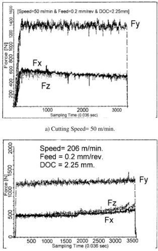
ii) Effect of Cutting Speed
Model (1) indicates that cutting speed has an almost equal opposite impact to that of feed rate on the surface roughness. At lower cutting speeds, higher roughness peaks are due to high friction accompanied by low strain rate (low elastic-plastic deformation)
(BUE). When BUEseparates, it generally carries a tiny portion of insert material. This irregular mechanism affects the edge surface leading to micro scratches on the machined surface. Moreover, the frequent mechanism of formation and removal of BUE usually results in system instability through inducing an exciting force into the system. Eventually, the tool oscillates randomly and uncontrollably projecting its stochastic fingerprints on the machined surface. The above facts are reflected on the dynamic amplitude of the force signals in Fig. 3a (low cutting speed of 50 m/min) comparing to that when a high cutting speed level of 206 m/min is used, Fig. 3b. While at low cutting speed, Fig. 3.a, dynamic amplitude (fluctuations) domain ranges from 1200-1425 N, a tighter domain of maximun 100 N is observed for the high cutting speed level, Fig. 3b. As cutting speed increases, Fig. 3b, friction is reduced and strain rate increases which is accompanied by force decrease leading to a more stable process or, better surface roughness. Measured corresponding values of surface roughness Ra are found to be 7.0 and 1.6 µm for cases a and b respectively and, this reflects the extent of surface quality improvement due to cutting speed increase.
a) Cutting Speed= 50 m/min.
b) Cutting Speed= 206 m/min.
Figure 3. Effect of cutting speed on the nominal dynamic Fforce signals at the initial wear stage.
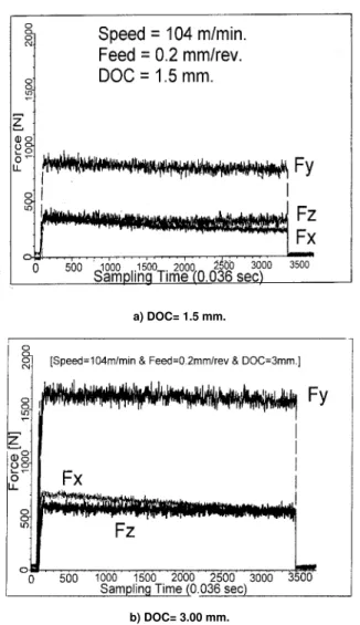
iii) Effect of Depth of Cut
J. of the Braz. Soc. of Mech. Sci. & Eng. Copyright © 2008 by ABCM July-September 2008, Vol. XXX, No. 3 / 225 constant cutting speed and feed rate of 104 m/min and 0.2 mm
respectively. Corresponding measured values of the surface roughness Ra are found to be almost constant value of 2.95 and 2.88 µm respectively. However, dynamic behavior of the force signals for higher depth of cut indicates a very slight variation in favor of system stability especially for the feeding force component Fx.
a) DOC= 1.5 mm.
b) DOC= 3.00 mm.
Figure 4. Effect of depth of cut on the nominal dynamic force signals at the initial wear stage.
Progressive Wear-Force-Surface Roughness
Interrelationship
Following the initial wear stage, tool enters its second phase at which wear progressively develops with almost a constant rate. This stage lasts most of the edge useful lifetime until edge fails catastrophically as it reaches the temperature sensitive plastic deformation region. To avoid system disorder resulting from catastrophic failure during realtime machining, it has been the goal of many investigations is to have an appropriate early warning and tool change strategy in which tool is not left in service until the failure occurs. A great challenge is usually imposed since, in most situations, transmission between second and third wear phase occurs almost instantaneously, Fig. 5.
Figure 5. Dynamic force signals at edge’s catastrophic failure at high cutting speed.
In order to evaluate surface roughness at the second wear stage (Ra in µm), it is expected to be wear and time dependent as:
m), ( ) ( )
(t Ra iw boNwb1Fwb2Ncwb3tb4 µ
Ra = + (2)
in which Nw, Fw, and Ncw are nose, flank, notch wear respectively, while t is the aggregate cut time.
Using non-linear estimation procedures in association with experimental data within both initial and constant wear rate zones has led to the following predictive form:
m). ( ) 10 (N ) 10 ( ) 10 ( ] 07 38 . 7 [ V ) 10 ( ] 2356 . 211 [ ) ( ) 3786 . 4 ( ) 8899 . 2 ( ) 6175 . 1 ( ) 5747 . 3 ( (-1.1096) ) 0932 . 1 ( µ t cw Fw Nw E f t Ra − − − × × × − + × = (3)
Another modeling strategy to enhance model significance is thought to be through the use of average wear values (Aw), as a mean of the three wear modes reading, in place of individual wear values:
m). ( ) 10 (Aw ] 06 12248 . 3 [ V ) 10 ( ] 2356 . 211 [ ) ( ) 9654 . 3 ( ) 6192 . 7 ( ) (-1.1096 ) 0932 . 1 ( µ t E f t Ra − × − + × = (4)
Model (4) is less complicated and results in relatively improved t-test values. Another model approach is the use of the average wear rate (Awr): ) 1761 . 4 ( ) (-1.1096 ) 0932 . 1 ( ) 100 (Awr ] 00128 . 0 [ V ) 10 ( ] 2356 . 211 [ ) ( − × + × = f t Ra (5)
Model (5) showed better statistical characteristics in addition to the fact that it is easy to manipulate without affecting the functional implementation of the roughness-wear trend.
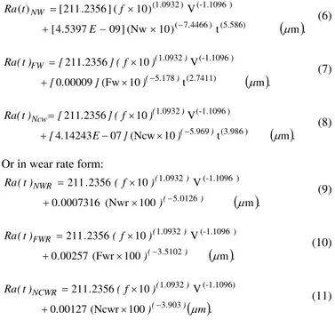
Individual Effect of Wear Modes
( )
m. t ) 10 (Nw ] 09 5397 . 4 [ V ) 10 ( ] 2356 . 211 [ ) ( (5.586) ) 4466 . 7 ( ) (-1.1096 ) 0932 . 1 ( µ − × − + × = E f t Ra NW (6)( )
m. t 10 (Fw 00009 0 V 10 2356 211 (2.7411) 178 5 ) (-1.1096 0932 1 µ ) . ( ) . ( FW ) ] . [ ) f ( ] . [ ) t ( Ra − × + × = (7)( )
m. t 10 (Ncw 07 14243 4 V 10 2356 211 ) (3.986 969 5 ) (-1.1096 0932 1 µ ) . ( ) . ( Ncw ) ] E . [ ) f ( ] . [ ) t ( Ra − × − + × = (8)Or in wear rate form:
( )
m. 100 (Nwr 0007316 0 V 10 2356 211 0126 5 ) (-1.1096 0932 1 µ ) . ( ) . ( NWR ) . ) f ( . ) t ( Ra − × + × = (9)( )
m. 100 (Fwr 00257 0 V 10 2356 211 5102 3 ) (-1.1096 0932 1 µ ) . ( ) . ( FWR ) . ) f ( . ) t ( Ra − × + × = (10)( )
m. ) . ) f ( . ) t ( Ra ) . ( ) . ( NCWR µ 903 3 (-1.1096) 0932 1 100 (Ncwr 00127 0 V 10 2356 211 − × + × = (11)Comparing normal models (6-8) and those for wear rate (9-11), the latter give slightly better statistical characteristics regarding t-test value for (bo). In fact, this could be a result of reducing the number of independent variables (less degrees of freedom).
The influence of tool edge failure modes on the surface roughness may be explained in the light of the corresponding recorded force signals. Modelling approach of the experimental data usually represents the overwhelming deterministic trend of the response under investigation. This means that much useful information about random modes of edge failure is not emphasized in the developed model. On contrast, the use of the dynamic force signals is proved to be very sensitive to any disturbances due to any irregular traces of edge failure. The force signals at different directions are found, to
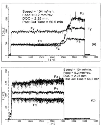
different extent, a better indicator about the existence of the different modes of edge failure and breakage than that produced by a deterministic static model. Figure 6 shows the last three subtests (two minutes each) of the wear-time test at which failure initiates and finally fails. As tool edge approaches failure, Fig. 6b, both feeding and radial components increase in the static magnitude comparing to the preceding subtest, Fig. 6a, while the vertical component shows wider dynamic fluctuations reflecting the existence of system instability. Also, at edge failure, Fig 6c, the radial component Fz is significantly increased both dynamically and statically while a limited increase is observed in the feeding component Fx. The vertical component continues to attain a high dynamic instability due to edge failure. The distinguished increase in the radial component is, in fact, a response to the type of wear modes and its location on the cutting edge. After examination, the onset of the edge breakage is observed only at the nose area normal to workpart axis. Due to such mode of edge failure, surface quality deteriorates as the corresponding surface roughness values Ra of the three successive subtests shown in Fig. 6 are measured to be 9.5, 10 and 12 respectively. Therefore, while it may be stated that the tool breakage can be detected either by the static force increase in the radial Fz force component or by the dynamic fluctuations of the vertical force component Fy. The surface roughness of the process is observed to be in a good agreement with the dynamic records of the vertical force component Fy. However, in cases when a high wear rate develops due to high cutting speed, Fig. 5, a wear spreads over the whole edge with a regular pattern causing an increase in both feeding Fx and Fz force components. However, with such a stable conditions, only a slight static and dynamic influence is noticed on the vertical component Fy. The dynamic attitude of the vertical component Fy at the instant of tool failure seems to be negatively affected by the employed cutting speed. At low cutting speed of 50 m/min, Fig. 6, vertical force component Fy responds drastically to edge failure while at high cutting speed of 206 m/min, Fig. 5, it is seldom affected.
J. of the Braz. Soc. of Mech. Sci. & Eng. Copyright © 2008 by ABCM July-September 2008, Vol. XXX, No. 3 / 227 Figure 7 gives evidence on how various force components are very
sensitive to represent the actual distribution of wear over the cutting edge. At the end of subtest (a), Fig. 7a, tool nose is severely deformed as edge hits a hard spot on the machined surface. Accordingly, the radial force component Fz suddenly responses reaching almost threefold of its original value while the feeding component Fx has attained a smaller increase of only about 40% of its original value. The vertical component Fy is slightly affected both in static magnitude and dynamic domain. Four minutes later, Fig. 7b, a total system instability, both axially and radial, is attained with the highest magnitude for the Fz component. The values of the surface roughness Ra are 4.0 and 6.0 (µm) for the two subtests. This change in the surface roughness is affected due to two concurrent reasons; the edge deformation at the nose and the corresponding system instability. Again, at moderate-to-high cutting speeds, Fy does not precisely respond to the tool deformation and, therefore, it cannot be trusted as a grant as a relevant indicator.
However, it seems that the attitude of different force signals is affected by the type, the location and the configuration of the wear mode. Figure 8 shows force signals of thee successive subtests carried out at low cutting speed of 72 m/min and moderate-to-high feed rate of 0.3 mm/rev. While Fig. 8. a represents the stable process, Fig. 8.b is for the subsequent subtest at which edge failure initiates at both the flank and the notch areas. Wear continues with higher rate within the last subtest of the experiment, Fig. 8.c, at which tool is completely failed. Again, the vertical force component Fy responses dynamically to the occurrence of the flank and the notch wear at hostile conditions of low cutting speed and high feed rate. However, it is observed that the feeding component Fx is the most sensitive to the existence of both the flank and/or the notch wear. Due to such edge deformation, corresponding increase in the roughness values is observed with Ra of 7.3, 8 and 10 (µm) respectively for subtests a, b and c respectively.
Figure 7 Effect of local nose deformation on force attitude at moderate cutting speed.
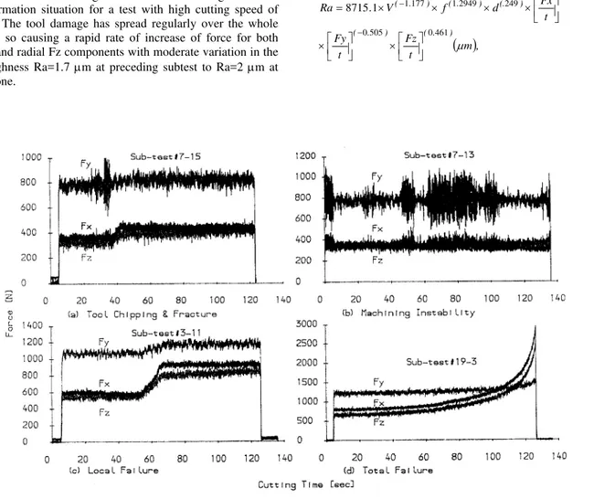
In addition to the previously discussed common types of edge wear and deformation, which results basically from the friction of tool-workpiece interface, there are some other irregular deformation modes resulting from the possible imperfections in the tool materials and from any other unexpected reasons such as chipping, micro breakage or even system instability due to bad design of some of the system elements. The effect of possible disturbances during cutting on the behaviour of force signals is illustrated by a sample results as shown in Fig. 9. As shown in Fig. 9a, tool chipping and fractures usually causes a sudden increase in the magnitude of both feeding Fx and radial Fz components as well as a temporary dynamic effect of the vertical force component Fy. When chipping and fracture occur, a new and wider tool-workpiece contact area is developed, and this increases the normal force on the tool’s clearance face. At the case of process instability, Fig, 9b, the vertical component Fy tends to be the most sensitive to the machining stability, see also Fig. 9.b. Figure 9.c illustrates the dynamic force signals interval at which the edge has hit three adjacent hard spots in the workpiece material and, as a result, a failure has occurred only at both the nose and the flank areas leading to force magnitude increase with the vertical component is slightly affected. It is observed that this wear mode has a high impact on the surface roughness where its values has increased from Ra=2.7 µm at the preceding subtest to Ra=4.5 µm for the current subtest. Fig 9.d shows the force signals at the plastic deformation situation for a test with high cutting speed of 206 m/min. The tool damage has spread regularly over the whole contact area so causing a rapid rate of increase of force for both feeding Fx and radial Fz components with moderate variation in the surface roughness Ra=1.7 µm at preceding subtest to Ra=2 µm at the current one.
Mathematical Modeling of the Force-Surface Roughness
Interrelationship
From the aforementioned discussion, too many observations and concluding remarks are obtained. First all, the surface quality is not of constant nature throughout the whole tool lifetime and, this is due to the inevitable variability especially those associated with the instantaneous state of the cutting edge (Oraby et. al. 2004). Second, there is a universal agreement regarding the strong correlation between the existence of the different modes of edge wear and deformation and the corresponding changes in the cutting force either statically (Oraby & Hayhurst 1991, Youn & Yang 2001, Oraby & Hayhurst 2004) or dynamically (Oraby 1995b). Therefore, it may be beneficial to relate the surface roughness to the relevant cutting forces using the appropriate deterministic mathematical tool. To get an empirical equation to relate the surface finish to the cutting forces, the experimental data, including about 660 points, are used in association with the nonlinear routine available in the SPSS computer program. This has led to the development of the following model: in which t is the aggregated cutting time in minutes.
( )
m, tFz t
Fy
t Fx d
f V
. Ra
) . ( ) . (
) . ( ) (. ) . ( ) . (
µ
461 0 505
0
018 0 249
2949 1 177 1 1 8715
⎥⎦ ⎤ ⎢⎣ ⎡ × ⎥⎦ ⎤ ⎢⎣ ⎡ ×
⎥⎦ ⎤ ⎢⎣ ⎡ × × ×
× =
−
− −
(12)
J. of the Braz. Soc. of Mech. Sci. & Eng. Copyright © 2008 by ABCM July-September 2008, Vol. XXX, No. 3 / 229 Model (12) produces a quantitative assessment of the effect of
each of the cutting parameters along with the variation in the force rate on the surface roughness. As discussed in model (1), in contrast to the effect of depth of cut, both cutting speed and feed rate have an opposite similar strong impact on the roughness. Regarding the effect of force rate, the feeding component Fx shows a minor impact on the surface roughness while both the power Fy and the radial Fz components indicate a strong influence. Technically, this does not necessary mean that feeding force component Fx itself is of no effect on the surface roughness but it is possible that its influence is diluted within the effect of the feed rate which is already included into the developed model. The rate of change of the radial force component Fr shows a positive effect on the roughness and, this can be justified as it is most affected by the deformation on the nose area which has the most influence on the surface finish. The negative power of the rate of change of the vertical force component may be attributed to its dynamic effect and system stability. As time goes on, the developed wear on the nose area spreads out over the cutting edge and becomes more evenly distributed and, therefore, resulting in a more tight dynamic fluctuations or, a more stable process leading to better surface finish.
Modelling statistical output produced proves of model significance with 90.5% correlation factor R2. However, the 95% confidence interval shows wider domains (high standard error) for coefficients of both the depth of cut and the feeding force rate. This suggests a better strategy considering the exclusion of these two parameters. This has led to the establishment of the following more compact model (4).
( )
. 182 . 12212) 444 (.
) 498 . ( ) 293 . 1 ( ) 219 . 1 (
m t
Fz
t Fy f
V Ra
µ ⎥⎦ ⎤ ⎢⎣ ⎡ ×
⎥⎦ ⎤ ⎢⎣ ⎡ × ×
×
= − −
(13)
Model (4) presents a tight and adequate representation of the functional relationship between the surface roughness Ra and the cutting parameters (Cutting Speed and Feed Rate) along with rate of change in both the vertical and the radial cutting force components.
This can be the core of an adaptive control optimization ACO strategy in which the surface roughness is monitored and controlled throughout the force measurement together with the operating cutting parameters. This can be further extended to include a secondary objective as edge wear is monitored using wear-roughness models developed in the previous study (Oraby et. al. 2004).
Conclusions
The cutting force is one of the most practical responses to handle in adaptive control techniques due to its easy-to-measure and manipulate features and due to its strong correlation with the edge wear which is the most controlling factor of the surface roughness. It is intended in the current work to analyze and evaluate the tool-wear-force-surface roughness dependency and, eventually, to mathematically relate the degree of the instantaneous roughness of the machined surface to the variations encountered in the various static and dynamic force components.
At the initial wear stage, the main parameters controlling the surface roughness are the employed feed rate and cutting speed. As machining continuous, various types of wear and deformation modes develop on the cutting edge resulting in variations in the surface quality which can be related, to different extents, to the rate of change in forces.
Among wear modes, the nose wear is found to be the predominant mode with a strong influence on the radial force component Fz. The flank and the notch deformation usually affect the feeding force component Fx. Variations in the vertical force component Fy usually depends on the severity of the employed cutting parameters, the mode and the location of the deformation and, on the aggregated cutting time. At high cutting speeds, a more stabilized process leads to less cutting fluctuations. As time passes, high wear rate results and the wear becomes more evenly distributed over the cutting edge leading to more stable process and, accordingly, better surface finish. Random modes of tool deformation, such as edge chipping and micro breakage, can be quantitatively assessed by the changes in the static values of each of Fx and Fz while they can be qualitatively detected by the changes in the dynamic domain of the vertical force component Fy.
Most of the aforementioned findings are reflected on the developed nonlinear mathematical models to relate the surface roughness to both the cutting parameters and the measured instantaneous force components and, this can be the base of an adaptive control AC technique.
References
Azouzi, R. & Guillot, M. 1997, “Online Prediction of Surface Finish and Dimensional Deviation in Turning using Neural Network Based Sensor Fusion”, International Journal of Machine Tools and Manufacture, Vol. 37, No. 9, pp. 1201-1217.
Balakrishanan, P. & DeVries, M. F, 1983, “Analysis of mathematical Model Building Techniques Adaptable Data Base Systems”, Proc. NAMRC-XI, pp. 466-475.
Chen, J. and Lee, S. 2003, “An-Line Surface Roughness System using an Accelerometers in Turning Operations”, Journal of Engineering Technology.
Choudhury, S. K., Jain, V. K., & Krishna, S. R. 2001, “On-Line Monitoring of Tool Wear and Control of Dimensional Inaccuracy in Turning”, Trans. ASME, Journal of Manufacturing Science and Engineering, Vol. 123, No. 1, pp. 10-12.
Dawson, G. 2002, “Machining Hardened Steel with Polycrystalline Cubic Boron Nitride Cutting Tools”, Ph.D. Thesis, Georgia Institute of Technology.
Draper, N. R. & Smith, H., 1967, Applied Regression Analysis, Wiley, New York, NY, USA.
Ezugwu, E. O., Fadare, D. A., Bonney, J., Das Silva, R. D. & Sales, W. F. 2005, “Modelling the Correlation Between Cutting and Process Parameters in High-Speed Machining of Inconel 718 Alloy using an Artificial Neural Network”, International Journal of Machine Tools & Manufacture, Vol. 45, pp. 1375-1385.
Fang, X. D. & Shahi, H. S. J. 1997, “A New Algorithm for Developing a Reference-Based Model for Predicting Surface Roughness in Finish Machining of Steels”, International Journal of Production Research, Vol. 35, No. 1, pp. 179-199.
Grzesk, W. and Wanat, T, 2005, “Comparative Assessment of Surface Roughness Produced by Hard Machining with Mixed Ceramic Tools Including 2D and 3D analysis”, Journal of Materials processing Technology,
Vo. 169, No. 3, pp. 364-371.
Hines, W. W. & Montgomery, D. C. 1982, Probability and statistics in Engineering and Management Science, John Wily&Sons, 2nd edition.
Kamarthi, S. V. & Kumara, S. R. T. 2000, “Flank Wear Estimation in Turning through Wavelet Representation of Acoustic Emission Signals”,
Trans. ASME, Journal of Manufacturing Science and Engineering, Vol. 122, No. 1, pp. 12-19.
Liang, S. Y., Hecker, R. L. & Landers, R. G. 2002, “Machining Processes Monitoring and Control: The State-of-the-Art”, Proceedings of IMECE’2 ASME International Mechanical Engineering Congress & Exposition, New Orleans, Louisiana, USA.
Lim, C. Y. H., Lim, S. C. & Lee, K. S. 1999, “Machining Conditions and the Wear of TiC-Coated Tools”, Wear Progress in Manufacturing, ASTM. STP 1362, pp. 57-69.
Machinability Data Handbook Machinability Data, Machinability Data Center, 2nd Edition 1972.
Oraby, S. E. & Hayhurst, D. R., 1990, “High-Capacity Compact Three-Component Cutting Force Dynamometer”, International Journal of Machine Tools & Manufacturing, Vol. 30, no. 4, pp. 549-559.
Oraby, S. E. & Hayhurst, D. R., 1991, “Development of Models for Tool Wear Force Relationships in Metal Cutting”, International Journal of Mechanical Science, Vol. 33, No. 2, pp. 125-138.
Oraby, S. E. 1995b, “Monitoring of Machining Processes via Force Signals - Part I: Recognition of Different Tool Failure Forms by Spectral Analysis”, Wear, Vol. 33, pp. 133-143.
Oraby, S. E. & Hayhurst, D. R. 2004, “Tool Life Determination based on the Measurement of Wear and Tool Force ratio Variation”, International Journal of Machine Tools & Manufacture, Vol. 44, pp. 1261-1269.
Oraby, S. E., Al-Mudhaf, A. F, & Hayhurst, D. R. 2005, “A Diagnostic Approach for Turning Tool based on the Dynamic Force Signals”, Trans. ASME, Journal of Manufacturing Science and Engineering, Vol. 127, pp. 463-475.
Rao, C. S. & Srikant, R. R. 2004, “Tool Wear Monitoring – An Intelligent Approach”, Proc. Institution of Mechanical Engineering (IMECH2004), Part B: Journal of Engineering Manufacture, Vol. 218, pp. 905-912.
Schuetz, G, 1994, “Rx for Ra measurements – average roughness”, Modern Machine Shop (www.mmsonline.com).
Shao, H., Wang, H. L. & Zhao, X. M. 2004, “A Cutting Power Model for Tool Wear Monitoring in Milling”, International Journal of Machine Tools & Manufacture, Vol. 44, pp. 1503-1509.
Suresh, P. V. S., Rao P. V. & Deshmukh, S. G. 2002, “A Genetic Algorithm Approach for Optimization of Surface Roughness Prediction Model”, International journal of Machine Tools & Manufacture, Vol. 42, No. 6, pp. 675-680.
Xiao-Qi, C., Hao, Z. & Wildermuth, D. 2001, “In-process Tool Wear Monitoring through Acoustic Emission Sensing”, SIMTECH Technical report (AT/01/014/AMP), Automated Material Processing Group. Automation Technology Division, Singapore Institute of Manufacturing Technology.
Youn, J. W. & Yang, M. Y. 2001, “A Study on the Relationships Between Static/Dynamic Cutting Force Components and Tool Wear”, Trans ASME, Journal of Manufacturing Science and Engineering, Vol. 123, No. 2, pp. 196-205.
Zecchino, M, 2003, “Why average roughness is not enough: advances in three dimensional measurement techniques such as optical profiling have given engineers, process designers, and quality control professionals a significantly improved toolkit for describing surfaces”, ASM, Advances Materials & Processes.