Abstract
Search and rescue missions are complex operations. A disaster scenario is generally unstructured, time-varying and unpredictable. This poses several challenges for the suc-cessful deployment of unmanned technology. The variety of operational scenarios and objectives are generally not feasible as information only becomes available during mis-sion. The ICARUS project responds to this challenge by developing a heterogeneous interoperable team. This chapter describes our approach to multi-robot interoperability, understood as the ability of multiple robots to operate together, in synergy, enabling multiple teams to share data, intelligence and resources, which is the ultimate objective in multi-robot multi-domain systems, our implementation of an interoperability frame-work and several examples of multi-robot cooperation of the ICARUS robots in realistic search and rescue missions.
1. Introduction
general, large scale systems aiming at solving all problems with one single type of platform
by increasing the interactions between these systems, making them aware of each other, exe-behaviours.
The ICARUS project involves a team of assistive unmanned air, ground and sea vehicles for for the operations, these systems must be able to collaborate as a seamlessly integrated team,
rotor, indoors multi-rotor, large UGV, small UGV, Teodor UGV, U-ranger USV, ROAZ USV,
had to be devoted to their integration as a team and this is the work described in this Chapter. systems have their own command and reporting protocols, and consequently require their own ground control stations. This profusion of protocols makes the cooperation between sys-and maintenance of multi-vehicle systems. The work described in this chapter aims at con-of heterogeneous teams.
The ultimate objective of the ICARUS project is to achieve robot interoperability, which can be understood as the ability of robots to operate in synergy to the execution of assigned mis-sions. Interoperability enables diverse teams to work together, sharing data, intelligence and resources.
ICARUS proposes the adaptation of all the vehicles to a single standard external interface as a method to ensure interoperability. Each robot development team is free to use their own tools -[1] very frequently used in software engineering. It essentially hides the complexities of the implementation and provides the outer components with a simpler interface. It is typically deployed as software library implementing a wrapper or adapter template. On one side, this library implements the interoperability standard interface and, on the other side, it provides -ware provided by each platform.
This approach may initially seem to reduce the level of integration among the agents if we com-pare it against natively sharing an internal protocol in all systems, but it promotes the maximum the common interface. In the long term, this has shown to improve the seamless integration of the maximum number of systems and domains at a lower cost. The integration of new platforms on-board hardware resources and communications are made available by the robot provider. Therefore, the ultimate goal of the work on the heterogeneous team is to consolidate a com-mon command, control and payload interface to be agreed and adopted by all robotics plat-forms and control ground stations (CGS) involved in an ICARUS operation. This approach provides a common framework for the development of collaborative unmanned assets,
mini-There are other advantages in using interoperability standards. The use of a widely accepted
as end-users rely on proven technology and the preliminary validation will focus only on de-risking the new developments. Another advantage of the use of standards is that it will facilitate the backwards and forwards compatibility between existing and future vehicles and
avoiding duplicating and re-inventing proven technology. During the initial steps of the work, the most relevant multi-domain interoperability protocols for unmanned systems were During this phase, several collaborations with other European [2] and NATO [3] initiatives,
modes, etc.) or constraints (i.e. computational resources, communication bandwidth, etc.). Therefore, in order to methodically evaluate the existing initiatives, an analysis of the ICARUS generate what we referred to as the project interoperability needs. Any information that was
analysis of other potential vehicles that could be integrated into the system in the future. -4]. We use it to describe the set of concepts required levels from robots to systems, capabilities and sensors, and their relationships and assump-and Automation Society (IEEE-RAS) created a working group named Ontologies for Robotics
5]. The work performed in ICARUS has a strict focus on heterogeneous multi-robot operations in and platforms involved in search and rescue missions.
This analysis resulted in a description of the set of multi-domain concepts and relationships or messages commonly found in unmanned systems. Table 1
and provides some example of interactions between systems.
The complete ontology was used in a gap-analysis for the evaluation of the existing standards as described in Section 3.
2.2. Interoperability levels
A key concept that enables interoperability among the largest number possible of unmanned
Category Description and examples
Transport Inter-process communication such as send, receive, broadcast, etc. Commands Generic accessories such as set, get, etc. for any standard concept Management
Telemetry Pose and velocity reports in appropriate system coordinates, etc. Telecontrol Teleoperation, waypoint and mission management, etc. Perception Imagery, ranging, audio, etc.
Manipulation
Mapping Maps, digital elevation models, point clouds S & Rintelligence Sectors, disaster alerts, humanitarian information Table 1.
[
-grated, accounting therefore for more integration strategies and combinations.
adapted to our project as follows.
Table 2. The levels of interoperability for each of the ICARUS systems are as shown in Table 3. 2.3. Adjustable automation
generally be remotely controlled. Most of these systems also provide on-board autonomy modules that allow the operator to plan a mission to be autonomously executed by the sys-realistic scenario, unexpected events are highly likely to occur and the intervention from the operator, such as manually overriding the mission execution, is often required. This increases the cognitive workload of the operator leading to stress and potential mistakes, which are even more critical in the context of multi-robot operations.
Adjustable automation (AA) is the ability of a robot to behave autonomously and dynamically and scenarios [7]. AA presents advantages when dealing with communication delays, human workload and safety [
In ICARUS, AA is achieved by supporting multiple levels of automation in the robots, e.g. fully autonomous, guided by the operator, and fully controlled by the operator. The C2I also
Level of interoperability
Indirect receipt/transmission of telemetry, control and payload data: the UxV data are received from (or sent to) another source (another CGS, web-server, etc.)
Direct receipt/transmission of UxV telemetry and payload data, but without control authority over it Direct control and monitoring over the UxV without launch and recovery. A dedicated control deployment and recovery, etc) and hand it over to the CGS once ready for mission
supports adjustable automation by automatically changing its display and control functions based on the relevance of the information, the current situation the robots encounter, and user preferences.
The level of automation of a robot is related to the degree of intervention of the human
opera-9 10
allocation, mission coordination, etc), which are mostly relevant for tightly coupled coordina-tion. In ICARUS, the levels of automation are understood in terms of tasks execution and are reduced to essentially three modes, as shown in Table 4.
depending on the robot operator choice, the mission plan priorities, workload and constraints of the mission and platform. As mentioned before, the concept of adjustable autonomy implies the ability to adapt and dynamically change between these levels of autonomy depending on situational changes. Some examples of adjustable autonomy within the context of ICARUS are:
• A UAV may provide fully-autonomous navigation in nominal conditions, but may fall back to semi-autonomous navigation in the presence of victims detected on the sensor stream. • The RC2 operator may have initially designed the mission to manually operate the outdoor
multi-rotor to inspect a building, but operation enters a highly complex area and he/she decides to enable semi-autonomous mode to ensure all corners are correctly surveyed.
Level of automation per robot
LoI 1 LoI 2 LoI 3 LoI 4 Notes X
UAVs are handled by the proprietary control stations. The system is handed over to the ICARUS C2I once in air
Outdoors multi-rotor X
Indoors multi-rotor X
Large UGV X
Small UGV X
U-ranger USV X U-ranger is a highly equipped and extremely fast USV. Integration is done through its proprietary CGS for safety purposes
ROAZ USV X ROAZ USV is primarily operated from a proprietary CGS. When ICARUS mission starts, control is handed over to the ICARUS C2I
Rescue capsule X
-remotely operated or waypoint guided. Such a large system should not be tasked with pre-operator should rely on the on-board autonomy, which is equipped with collision avoidance
Table 5 illustrates the automation levels available in each of the ICARUS platforms.
2.4. Multi-robot cooperation
the mission goals in order to provide a task-to-robot decomposition. This task allocation must
placed on the interface in order to implement these strategies. A heterogeneous team usually mission. Concepts such as roles, responsibilities, modes of operations and tasks may be part
The platforms involved in ICARUS have been carefully selected to help each other. In other words, they play complementary roles. Several ICARUS platforms grouped together form a address more complex missions by supporting each other.
Level of automation
Level 1 Teleoperation. No automation on-board the robot. The robot is directly controlled by the operator Level 2 Semi-autonomous. Execution capabilities. The robot is able to manage partially ordered sequences of
elementary tasks, and to return execution status of the tasks. An operator is supervising the mission from the RC2
Level 3
scheduling) Table 4.
Level of automation per robot
Long-endurance Outhoor multi-rotor Indoor multi-rotor Large UGV Small UGV U-Ranger USV ROAZ USV Rescue Capsule
-coordination strategy [11
approach where the cooperation and interaction between robots is negotiated during mission planning. The planning, coordination, and therefore the ultimate responsibility fall on the ICARUS team operator and occur at the C2I. Therefore, this coordination approach relaxes to a certain extent the need to have multi-robot related concepts in the interoperable inter-face. The C2I encapsulates this functionality and can interact with each asset individually. was taken into account in the analysis described in the next section.
-accomplish, for instance, the assessment of a disaster area. The mission planner is responsible
-lance, mapping, victim detection and communications relay capabilities. These characteristics plan is therefore built upon the concepts of roles, tasks and responsibilities.
teams. Table 6
One of the core services required from all the platforms is the dynamic discovery of features. It allows robots to advertise their capabilities over the network, enabling dynamic planning and
System Responsibilities C2I
SAR team allocation to sectors Robot(s) allocation to teams Teams monitoring and control RC2 Operations scheduling
Roles allocation Robot task planning Robots monitoring and control Robot Task plan execution
Progress and status report Table 6. ICARUS goals to roles and tasks decomposition.
roles during a mission depending on the responsibilities that the C2I allocates to it. The
allo-set of actions. Each task could be decomposed into subtasks. This subdivision could continue iteratively until a primitive task is reached. Table 7
in the ICARUS concept of operations.
3. Analysis of existing standardization initiatives
that can be used consistently to ensure that materials, products, processes and services are 12]. In the context of interoperability, a standard shall
unambigu-for interoperability of unmanned systems [3 yet a fact.
Roles Description Modes
Scout Provides a quick assessment of an
unexplored area or route Traversability/best route exploration (UAS) Surveyor Scan in detail an area or building to
support a thorough assessment and inspection (structural integrity, victims,
higher altitude, rotor-craft at lower altitude) or a structure (rotor-craft). Building indoor inspections (small rotor-craft and small ground vehicle)
Observer Steady target observation and assessment, including victims and structures
Steady hover over a target (rotor-craft), including harsh weather conditions. Victim medical assessment outdoors (rotor-craft and USV) and indoors (small rotor-craft and ground vehicles)
Searcher Victims search Outdoors human detection on IR (UAS and USV), indoors (small rotor-craft and UGV)
Rescuer Support to victim rescue
vehicle) or support human rescuers
Deliverer Safety kit delivery. Robot delivery Delivery of a survival kit to a victim, aerial (rotor-craft) or terrestrial (UGV)
Cruiser Travel to a destination All platforms when transiting to a new location where another role is enabled. The larger platforms may also act as a carrier of tools, debris and smaller robotics assets Table 7. Examples of ICARUS roles.
•
• Partially operational resources.
multiplatform system. The second group includes initiatives that are, either very popular on show some relevant contributions but they do not provide interoperability for all the possible types of platforms, systems and range of application.
The lack of a single standard of reference for interoperability of unmanned systems makes
existing standards, by combining them into one, or by proposing a brand new standard, would obviously solve most of the problems, but it would have serious implications both in industry and other programs that have adopted them as their standard [13]. This is clearly beyond the possibilities of the ICARUS project on itself.
14] and others related, and the Joint Architecture for Unmanned Systems—JAUS [ ]. They are both stable, and reconnaissance (ISR) data, while JAUS is instead more devoted to command and control interfaces of the platforms, robot navigation and perception.
STANAG related standards are predominantly military and, even though they have been promoted for civil applications, their requirements are heavily demanding in terms of compli-systems have been developed to meet this standard. It is perhaps very relevant for the
interop-(NATO only), the focus on the bigger systems and the absence of open available
implementa-and it currently considers any unmanned system as a generic asset in order to become truly multi-domain. Its root is also military, but it was soon transferred to the Society of Automotive Engineers (SAE International) where it is currently hosted.
According to our analysis, JAUS is fairly aligned with the needs of small unmanned plat-forms in terms of the interoperability described in Section 2. Also, JAUS has been suc-cessfully demonstrated in recent years for collaborative UAV-USV cooperative missions [15]. A quite direct traceability between ICARUS needs and the JAUS service sets is easily
derived. It is already compatible with popular transport protocols (TCP, UDP, serial) inde-already multi-environment (air, ground and maritime). There exist both commercial and open source implementations. Unfortunately, there is a fee to access the JAUS documenta-tion which may prevent some providers from using it. Nevertheless, the cost is deemed reasonable.
-development of small-unmanned systems, but they do not formally satisfy the interoperabil-ity requirements like the standards mentioned previously. They should remain at the plat-form level and the platplat-forms should comply with an external interoperability standard. It is
-4. Interoperability standard
Joint Architecture for Unmanned Systems (JAUS) [ ]. JAUS is a service-oriented architecture
details required to comply with the ICARUS interface.
4.1. Service sets
The interoperability interface is a service-oriented architecture (SoA). The most common
ser-• Core Service Set (SAE AS5710 [17]): essential services such as transport, events, discovery, etc.
• ]): mobile platforms services.
• 19]): platform-independent sensor capabilities.
• 20]): platform-independent capabilities common
across all serial manipulator types.
the functionalities provided by some of the platforms were not supported by these standard services. We refer to this as the gap analysis. Table 8 shows some of these gaps.
This new non-standard service set is shown in the following Figure 2.
Figure 1. Relevant JAUS services (source: ICARUS).
Gaps analysis
Outhoor quadrotors Indoor quadrotors Ground robots Large sea vehicles Survival kit deployment
Rescue capsule deployment enable/disable
Platform extended status Manipulator tool selection Voice transmission
(rules) for data exchange are available. There are generally three types of messages: query, an interface to the transport layer. Therefore, ICARUS interface is, in principle, independent available for the UDP protocol.
have been made:
• An ICARUS team is considered a system,
•
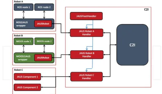
• As described later, a node may contain several components. But a component will imple-ment only one service, plus the core services, which are always present. This restriction allows the C2I to dynamically discover each of the services available on each robot. Therefore, an ICARUS system is depicted in Figure 3.
5. An interoperable layer: the ICARUS library
All this functionality is provided to the ICARUS robotics partners as a software library referred to as the ICARUS interoperability layer. This module acts as a bridge between their internal and external development frameworks. This interoperability layer is also responsible for the integration of the ICARUS communication network and the command and control station on each individual platform.
robotics systems nowadays are based on either proprietary or open-source middleware (such as ROS). To accommodate these systems into an ICARUS compliant network, an alterna-Figure 4 illustrates both cases, native integration (Robot C) and through an adapter (Robot A using ROS, and Robot B using MOOS).
The following sections describe the software classes encapsulated within the library and depicted in the previous diagram.
5.1. JAUS robot
JAUS robot encapsulates all the functionality required on-board the vehicle. It represents a subsystem in the JAUS topology (see Figure 3). In the ICARUS JAUS interface, a subsystem will
contain only one node. This approach will allow us to provide a component name to each
ser-There are two types of services available on a JAUS robot in addition to the core services: sen-sors and drivers.
Sensors provide access to information generated on the robot (i.e. global pose, image, etc.).
•
of JAUSRobot is myRobot, the following statement adds a GlobalPoseSensor service to our robot:
JAUSRobot myRobot;
myRobot.AddGlobalPoseSensor (‘OEMStar_GPS’, AT_1_HZ); •
lines will update the current GlobalPose of myRobot: JAUS::GlobalPose globalPose;
myRobot.globalPoseSensor->SetGlobalPose(newGlobalPose);
Drivers, on the other hand, provide access to actuation capabilities provided by each robot (i.e. go to waypoint). There is an equivalent function required to integrate this functionality:
•
-stance of JAUSRobot is myRobot the following line is adding a AddGlobalWaypointDriver service to receive waypoints request in global coordinate frame:
JAUSRobot myRobot;
myRobot.AddGlobalWaypointDriver(‘global_waypoints’, authority_code);
The authority code parameter of these services is used for pre-emption and needs to be set lower to the one of the client accessing the driver. Otherwise, commands from the client are ignored.
Therefore, JAUSRobot creates a JAUS component for every new Sensor and Driver. This
The ICARUS JAUS interface is based on callbacks for message reception. One more function will register a local callback in order to receive any message coming from the JAUS network:
void localProcessMessage(const JAUS::Message* message){ } myRobot.RegisterJAUSMessageCallback(localProcessMessage); 5.2. JAUS C2I
On the C2I side, two classes have been designed:
includes the functionality to discover subsystems and services on the JAUS network and
retrieving their services names: myFleet.DiscoverFleet();
On the other hand, the following line also allows checking for system updates: myFleet.RefreshFleet();
In terms of JAUS, it represents a basic JAUS component implementing the discovery service to retrieve the subsystems available in the network and their services.
5.2.2. JAUS robot handler
JAUS robot handler is responsible for managing a single robot. After the discovery process, the JAUS robot.
-ure the sensor service on-board the robot to send data for every new set. Periodic events will also be available in the future.
control service needed to send commands. 5.2.3. Management of the ICARUS communications
-A tight cooperation between the interoperability and communications layer allows for a smart
its priorities and other details. Given the current set and number of robots, sensors and the priorities for the mission assigned, the communications layer can assure a quality of service for each data stream.
between the interoperability and communication layers has enabled the dynamic selfcon -ery mechanism to retrieve all robots and their capabilities. This information is transferred to
lower priority. This a-priori priority allocation depends on the number of robots and their characteristics.
coordinator can at any time change the priority levels, enable new sensors, disable sensors that are not required, etc. The user is also informed with the current status of the network and
-faces (COMMS and JAUS):
• Register message. • Activation of a stream. • Deactivation of a stream. • Deactivation warning. • • -ed when, for instance, the COMMS interface starts running later than the JAUS interface.
•
loses a robot. •
a robot.
6. Individual platform adaptations
All ICARUS platforms have been adapted to the ICARUS interface. This automatically ensures the compatibility with the ICARUS C2I, enabling the multi-robot coordination and combination of data as later described in this chapter.
6.1. ROS to ICARUS robot node
All aerial platforms within the ICARUS project share a similar approach when it comes to software and hardware design. The hardware setup comprises a low-level board, responsible on-board pc) responsible for the autonomous navigation and payload data. These autopilots 21]. The on-board PCs, instead, run the robot operating system (ROS). A template has been devel-oped to integrate ROS-based platforms. Therefore, all of them have been adapted using this template.
particularly in terms of sensors equipment. The proposed strategy is to implement a ROS-based wrapper to subscribe to ROS topics and interface the ICARUS protocol. This node is intended to run on-board the robot and provides a wrapper of ICARUS interface. The node is
All the required services described in Figure 1 are available for ROS-based systems through
service:
<?xml version=”1.0”?> <launch>
<node pkg=”ros2jaus_node” type=”robot” name=”robot” output=”screen”> <!--ROBOT CONFIG -->
<param name=”subsystemName” type=”string” value=”ctae_robot”/> <param name=”subsystemID” type=”int” value=”99”/>
<param name=”nodeID” type=”int” value=”1”/> <!-- GLOBAL POSE -->
<param name=”globalPoseEnable” type=”bool” value=”true”/> <param name=”globalPoseSensorName” type=”string” value=”global_pose”/> <param name=”globalPosepUpdateRate” type=”double” value=”25”/> <param name=”globalPoseTopicName” value=”/EURECAT_robot/global_pose”/> </node>
</launch>
type. An analysis of the existing ROS messages was performed to select the most appropriate
ROS was either not existing, ambiguous or not valid. In these cases, a new message type was
• • • And publishes: • •
6.2. Other robot adapters
-sule runs OceanSys and exposes a data repository over which any software in the same net-work can subscribe and receive custom messages. ROAZ implements a similar system, but it is also ROS capable. The U-ranger on-board autonomy is developed in MOOS and imple-ments a behavioural control strategy.
A template example was provided to each of the partners, together with the use case for ROS and some documentation. Each partner was able to quickly adapt its existing frameworks to the standard interoperable interface and become complying with all ICARUS team technol-ogy, such as the communication infrastructure and the C2I. Tables 9 and 10 provide a sum-mary of the ICARUS services provided by each system.
IC A R U S se rv ic es p er ro bo t SE R V IC E A R O T A SO LA R U -R A N G ER R O A ZI I U C A P FI R EF LY SU G V LU G V G lo ba l p os e se ns or G lo ba l p os e (2 0 G lo ba l p os e (2 0 G lo ba l p os e G lo ba l p os e (2 0 G lo ba l p os e (2 0 G lo ba l p os e (2 0 G lo ba l p os e (2 0 G lo ba l p os e (2 0 V el oc ity s ta te se ns or Ve lo ci ty Fi rs t c am er a V is ua l V is ua l V is ua l Se co nd c am er a Ri gh t Th er m al Th er m al Ri gh t M an ip ul M an ip ul Th ir d C am er a Th er m al Th er m al Re ar ca m er a G ri pp er ca m er a Fo ur th c am er a V is ua l ca m er a R an ge s en so r ( Po in t cl ou ds ) Ra da r Po in t c lo ud Po in t c lo ud Po in t c lo ud G lo ba l w ay po in t lis t d ri ve r G lo ba l w ay po in ts G lo ba l w ay po in ts G lo ba l w ay po in ts G lo ba l w ay po in ts G lo ba l w ay po in ts G lo ba l w ay po in ts G lo ba l w ay po in ts Pr im it iv e dr iv er C m d ve lo ci ty C m d ve lo ci ty C m d ve lo ci ty C m d ve lo ci ty C m d ve lo ci ty C m d ve lo ci ty M an ip ul at or E nd po se po se M an ip ul at or jo in t se ns or Jo in t po si tio n Jo in t po si tio n M an ip ul at or e nd po se c on tr ol po se c on tr ol M an ip ul at or jo in t po si tio n dr iv er Jo in t po si tio n co nt ro l Jo in t po si tio n co nt ro l Ta bl e 9. IC A RU S se rv ic es p ro vi de d by e ac h ve hi cl e.
7. Field validations: examples of multi-robot cooperation
-ity of the ICARUS interoperabil-ity interface; (ii) experimentation on the possibilities on multi-robot cooperative search and rescue missions. The results from one of these trials showed that the work on interoperability enabled large-scale cooperative mapping with multiple aerial and ground robots in urban search and rescue [22].
-tion exercise of the ICARUS project described in Chapter 10. Three full-team valida-tions were
ICARUS custom services per robot
SERVICE AROT ASOLAR U-RANGER ROAZII UCAP FIREFLY SUGV LUGV First switch
driver Delivery DeployUCAP
Second switch
driver raft Manipulator Manipulator
Third switch
driver Reset Reset
Fourth switch
driver Audio Engine
Fifth switch
driver Speech
First 3-state
switch driver Grippercontrol Grippercontrol Second 3-state
switch driver Toolselector
Text sensor Text
Text driver Text Cmd
CO2 sensor CO2 sensor
Robot extended
status status status status status status
Video stream Video
stream Target
detection Victims Victims Victims Victims Victims Table 10. ICARUS custom services provided by each vehicle.
• •
• the participation in the euRathlon competition in September 2015 where the project re-ceived the Best Multi-Robot Coordination Award by the IEEE Robotics and Automation Society (RAS).
At this stage, all platforms had been integrated into the ICARUS system. After start-up, the cur-rent capabilities of the team could be dynamically discovered and the ICARUS C2I automati -work status are displayed. The operator can follow the progress of the mission, enable, disable or change the update rate of each of the ICARUS services. The operator can, at any time, request new missions, take manual control of the platforms that provide this service, resume previous missions, etc. All this functionality was exercised and demonstrated during the validations. Together, these large-scale operational exercises completed the validation of the ICARUS interoperability standard interface. Therefore, ICARUS as a project has demonstrated multi-domain multi-robot heterogeneous interoperability in realistic search and rescue operations. Some examples of the multi-robot collaboration experimented during ICARUS are described in the subsections below to illustrate the possibilities of multi-robot cooperation provided by an interoperable team.
7.1. Cooperative multi-stage aerial surveillance
In this multi-robot collaboration concept, the overall mission imposed by the human com -nario to be performed when relief agencies arrive on a crisis site. Assets to be deployed for this
•
-ing at an altitude of around 100 m. Note that the altitude limitation is deliberative, as many
-sessment of the sector, such that areas of interest can be selected.
•
of typically 40 m, it covers only a much smaller area. It is therefore used to provide a
high-• The multi-rotor aircraft also acts as observer system to provide high-resolution multi-view observation of points of interest (victims, buildings, etc.).
Operating multiple unmanned aerial systems in the same airspace is not easy from a safety perspective. In this case, vertical separation of the airspace was used for segregating the
-Figure 5 Figure 6 resolution assessment by the multi-rotor aircraft. As all data is geo-referenced, this informa-tion can be perfectly super-imposed on one another.
Figure 5. Multiple ICARUS aircraft in the air at the same time (source: ICARUS).
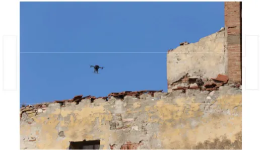
7.2. Aerial scouting for traversability analysis
A common problem for relief teams is that the route they have to take due to their designated
ground, including ICARUS unmanned ground vehicles. The aircraft scans the area to detect blocked and cleared routes to the destination point and sends updated navigation informa-tion to the ground team, such that the ground team can travel to the destinainforma-tion as quickly as possible. Figure 7
searching for obstacles on the way to the destination.
7.3. Victim search
-depending on the search and rescue context: •
victims and can count the number of victims. This operation can take place in an urban -quake (as shown in Figure 8), or in a maritime search and rescue context, where victims have to be found in the water (as shown in Figure 9).
• In indoor urban search and rescue scenarios, the indoor multi-rotor aircraft and the small-unmanned ground vehicle are deployed to collaborative search for surviving victims in-side semi-demolished buildings, as shown in Figure 10.
• In maritime search and rescue scenarios, the survival times in the water are often very short.
together with the ICARUS unmanned surface vehicles and the unmanned capsules. This enables the unmanned aircraft to immediately steer the maritime vehicles towards the
vic -sors (infrared cameras) enabling victim detection on board, but as these are relatively small
-orative victim search between aerial and marine platforms is therefore not impossible, but rescue aspect, as illustrated by Figure 11, which shows a victim in the water being tracked vehicle to a position in the neighbourhood of the victim, such that an unmanned capsule
Figure 9.
Figure 11. Collaborative maritime victim search and rescue operation involving aerial and maritime platforms (source: ICARUS).
7.4. Carrier
During any search and rescue operation, many assets need to be deployed as quickly as pos-platforms for small assets and equipment and also for other unmanned systems. As an example, the large unmanned ground vehicle acts as a carrier platform for the small-unmanned ground vehicle and both the ROAZ II and the U-ranger act as a carrier for the rescue capsules. They not only enable the cargo to be transported to the destination, without any extra burden to the human relief workers, but also act as deployment systems for the smaller unmanned systems. As an example, Figure 12 shows how the large unmanned ground vehicle deploys the small-unmanned ground vehicle on the top of a building, whereas Figure 13 shows how the rescue capsules are deployed from an ICARUS unmanned surface vehicle.
Figure 13. ICARUS unmanned surface vehicle deploying the unmanned rescue capsule (source: ICARUS).
Figure 12. ICARUS large unmanned ground vehicle deploying the small unmanned ground vehicle on the top of a building (source: ICARUS).
7.5. Communications relay
In the event of a large crisis, previously existing communication infrastructure is often bro-response operations. Collaborative unmanned systems can act as communication relay tools to extend the communication range over large distances. Of course, the assets which are most useful for this are the aerial tools, as they can provide line-of-sight communication relay over large distances. In the ICARUS project, an ad-hoc link-hopping network was developed, as detailed in Chapter 7 of this book, which allows to extend any communication link while the multi-rotor aircraft to act as communication relays for the ground and marine rescue teams. 7.6. Air, sea, ground cooperation during euRathlon 2015
Only seldom, rescue operations have to be performed which span three domains (air, ground, response protocols were ill prepared to approach such multi-domain crises. Therefore, the
workers under water, outside on the ground and inside in a semi-demolished reactor build-23]. These search and rescue operations require the simultaneous and coordinated deployment of unmanned aerial, ground and underwater vehicles, gathering environmental data and performing real-time
•
-bots to reach the open entrance to the building. Then, it mapped the area in the RGB, gray workers, leaks, etc.
• The Teodor UGV was used as carrier platform for the small UGV and for outdoor 3D mapping.
•
• The ROAZ II vehicle was used as a carrier platform for the MARES unmanned underwater vehicle.
• The MARES unmanned underwater vehicle was used for underwater detection and
Figure 14 Figure 15 illus-trates the Teodor UGV carrying the small UGV during the euRathlon challenge.
Figure 15. Teodor and small UGV during the euRathlon challenge (source: ICARUS). Figure 14. ICARUS rotorcraft during the euRathlon challenge (source: ICARUS).
Figure 16 shows the outcome of combining 3D maps obtained from the outdoor multi-rotor and ground platforms during the euRathlon challenge.
8. Conclusions
The work described in this chapter intended to integrate unmanned air, ground and sea
-requirements of ICARUS, emphasis was placed on initiatives considering multiple domains -There is still the need for a single multi-domain standard for interoperability, easily adapt-able to both large and small systems. The contribution of the ICARUS project focused on the selection of the most appropriate existing initiative (JAUS), the evaluation of its appli-cation to multi-robot Search and Rescue missions, the elaboration of recommendations for improvements, the adaptation of all ICARUS robots and the demonstration of the ICARUS interoperable and heterogeneous team in three large-scale demonstration, exploring multi-team.
Acknowledgements
Figure 16. 3D map of the crisis area, obtained by combining 3D maps from the aerial and ground platforms (source: ICARUS).
Author details
Daniel Serrano 1*, German Moreno1, Jose Cordero2 2, Shashank Govindaraj3,
Mario Monteiro Marques4 4 5, Alberto Grati5 ,
Massimo Tosa7, Anibal Matos , Andre Dias , Alfredo Martins 9
Balta10 and Geert De Cubber10
*Address all correspondence to: daniel.serrano@eurecat.org
1 Eurecat Technology Center, Av. Universitat Autònoma, Cerdanyola del Vallès, Barcelona, Spain 2 Integrasys SA, Madrid, Spain
3 Space Applications Services NV, Zaventem, Belgium
10 Department of Mechanical Engineering, Royal Military Academy of Belgium, Brussels, Belgium
References
[1]Sebastopol, CA: O'Reilly [2]
[3]
[4]
25 [5]
a core ontology for robotics and automation. Robotics and Autonomous Systems. 2013;61
[7]
Goodrich M, Olsen D, Crandall JW, Palmer TJ. Experiments in adjustable autonomy. In: IEEE Xplore Conference: Systems, Man, and Cybernetics, 2001 IEEE International Conference on, Volume: 3
[9] R. Parasuraman, T. B. Sheridan and C. D. Wickens, "A model for types and levels of human interaction with automation," in IEEE Transactions on Systems, Man, and
[10]
[11]
-dination. IEEE Transactions on Systems, Man, and Cybernetics, Part B (Cybernetics). 2004;34
[12]
home/standards.htm [13]
National Defense Industry Association (NDIA) Robotics Division; 2007 [14]
[15]
heterogeneous unmanned systems using the joint architecture for Unmanned Systems
Rowe S, Wagner CR. An introduction to the joint architecture for unmanned systems. Technical Report, Ann Arbor, MI, USA. Cybernet Systems Coorporation
[17]
-dards.sae.org/as5710/
[20] [21] [22] 34: 539-[23] -50