Abstract –This paper presents a design assistance methodology of low speed Switched Reluctance Machines (SRM) using field-based models. The magnetic properties of the iron, the number of rotor poles, and the number of poles per phase, all play a significant role in the machine design. The proposed comparison procedure uses field-based models along with scale models, based on similarity laws, to compare SRM designs. The field-based models are here applied in dimensional analysis of regular and non-regular topologies distinguished by different characteristics of electric and magnetic circuits. As an added value for this methodology, similarity laws take into account physical phenomena like thermal changes and magnetic saturation. Hypotheses introduced in the methodology formulation were verified by finite element analysis. This work is motivated by the application of SRM to direct drive wind converters and other low speed renewable energy systems. As an application example of this methodology, a non-regular topology with short flux-paths was compared with a regular prototype, 3-phase, 12/16, SRM, designed for a direct drive wind turbine: a gain of power per unit of mass is achieved with the former one.
Keywords – Field-based model, Similarity Laws, Low Speed Switched Reluctance Machine, Machine Design.
I. INTRODUCTION
Following the tendency of offshore wind turbine installation and the enlargement of the wind turbine capacity, directly driven generators are gaining increasing interest on this particular research field of low speed energy conversion. Direct drive energy converters take important benefits from the elimination of the gearbox, which has traditionally been used to interface a slowly prime mover shaft with the generator shaft. In fact, the gearbox is a considerable cost component that reduces the system reliability and its overall efficiency [1]. Furthermore, the actual trend of exploring the offshore wind resources makes robustness and reliability vital to the economic operation of wind turbines in that specific environment. This work is motivated by the application of Switched Reluctance Generator (SRG) to direct-drive wind turbines and other low speed renewable energy systems.
The option for the SRG topology analysis chosen by the authors for the proposed paper was also supported in the steep
rise of the neodymium permanent magnet price, which is taking the focus off the recently successful directly driven permanent magnet synchronous generator [2].
The Switched Reluctance (SR) machine is intrinsically a variable speed drive that can be easily controlled and matched to its load by settling the instants of energizing and de-energizing the stator phases [3]. Moreover, robustness and simple construction (only concentrated coils on the stator), control flexibility, high fault tolerance in a wide speed range [4-5], make this machine suitable for direct drive energy converters and attractive for harsh environmental applications. Previous and older treatments of SRG have focused on the design of high-speed SRG (see [6] and the references cited therein), which mainly rely on the regular magnetic structures of two opposing stator poles, per phase, and a minimal number of rotor poles. Further research efforts have been carried out during the last decades investigating magnetic topologies concerning the use of SRG in direct drive wind energy systems [7-9]. This paper introduces a simple and already known dimensional similarity-based methodology but built on another paradigm, ready to be used as an assistance design tool for estimation of SRG characteristics and comparison of regular and non regular SR topologies.
The field-based models and the formulation of similarity laws [10] proposed in this paper, provide the tools to compare other SRG topologies differentiated by diverse characteristics of electric and magnetic circuits and their own relative position. In addition, the use of this scale models methodology makes it easy to incorporate in the system treatment other physical phenomena, such as thermal effect and magnetic saturation by introducing some constraints. Thus, this work underlines dimensional and similarity arguments to extend previous discussions about SRG design into a more general context. In this paper, the scale models methodology is applied to the SRG design by evaluating and comparing a modular short-flux path topology with a 20kW regular SRG prototype operating at a rated speed in the region of 100 rpm for use in a direct drive wind turbine [11].
Field-based models for low speed switched
reluctance machine designs
P. Lobato*, J.A. Dente**, J.F. Martins***, A. J. Pires*
* Department of Electrical Engineering, ESTSetúbal, Polytechnic Institute of SetúbalCampus do IPS Rua Vale de Chaves Estefanilha, 2910-761 Setúbal, Portugal e-mail: [email protected]; [email protected]
** Instituto Superior Técnico, Lisboa , Portugal e-mail: [email protected]
*** Department of Electrical Engineering, FCT, New University of Lisbon Campus de Caparica, 2829-516 Caparica, Portugal
II. FIELD-BASED MODELS
A. Simplified Model
Concerning electromagnetic rotating systems, and within the scope of scale comparisons, it is desirable to work with simple models that represent the distribution of the flux density and magnetic energy. Those field-based models, supported in real system dimensions, can be used to estimate torque and power relationships. Making use of scale laws, an evaluation of relevant topology characteristics and parameters is expected to be achieved. Thereby, a model of a basic reluctance rotating system will be developed. The core is built with identical and isotropic material, assuming magnetic linear behavior and very high magnetic permeability.
In such SRG topologies, characterized by operating into the saturation region, the idea of constructing field-based models assuming linearity of the magnetic circuit may seem contradictory. However, as the saturation effect is extended to both topologies, it is possible to compare the characteristics of two structurally different topologies (for instance, having different numbers of poles), preserving certain dimensions of the magnetic circuit where the flux paths lie on. Therefore, the stator exterior diameter, the air gap length 𝜹𝜹𝒈𝒈, the radius of the air gap 𝑹𝑹𝒈𝒈 as well as the core length 𝑳𝑳 , will be fixed and kept constant.
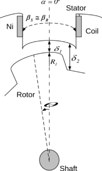
Fig. 1 shows part of a basic rotating reluctance system composed of two poles of equal dimensions, one having the capability of movement (rotor pole), with respect to the other which is in a fixed position (stator pole). One of these poles is magnetized by a coil with 𝑵𝑵 turns per pole and current 𝒊𝒊 . Hence, a torque is produced in order to reduce the reluctance of the magnetic circuit that constitutes the system, i.e., by varying the relative position of the poles.
In order to determine the position of the rotor pole and the quantities involved in the system, two angular coordinates are sufficient: 𝜶𝜶, the absolute coordinate associated to the inertial fixed referential and 𝜽𝜽, the relative coordinate that indicates the position of the rotor pole with respect to the stator pole. The rotor and stator pole arcs, 𝜷𝜷𝑹𝑹 and 𝜷𝜷𝑺𝑺 , are approximately equal. It is also assumed that stator winding comprises another coil, wound on a pole diametrically opposed to the first one, through which the flux-path closes by itself. Adding to the above mentioned assumptions, the fringing and leakage fields in the air gap will be neglected.
Ampère´s law applied to this reluctance system yields equation (1). Thus, the flux density 𝑩𝑩 at the air gap and the magnetic energy stored in the system 𝑾𝑾𝜹𝜹, are expressed by (2) and (3).
Ni ) , ( ) , ( H αθ δ αθ = (1) ) , ( Ni o ) , ( B θ α δ µ θ α = (2) ∫ = ∫ ∫ ⋅ =
δ µ δ δ V dV 0 2 B V dV B 0 ' dB H 2 W (3)It should be noted that (3) includes the presence of two volumes of air gap 𝑽𝑽𝜹𝜹 in the magnetic circuit. Regarding the air gap lengths, it is assumed that 𝜹𝜹𝟏𝟏≪ 𝜹𝜹𝟐𝟐 . In these terms, the
electromagnetic torque 𝑻𝑻𝒆𝒆 is given by the derivative of the coenergy 𝑾𝑾𝑪𝑪 with respect to the rotor position (4) and the maximum torque is given by (5). The electromagnetic power in the generator regime as well as in the motor regime, shown in Fig.2, is calculated using the average torque 〈𝑻𝑻𝒆𝒆〉 by (6).
∂θ θ δ ∂ ∂θ θ ∂WC(i, ) W (i, ) e T = = (4) 1 g LR 2 ) Ni ( o 2 1 1 1 g LR 2 ) Ni ( o T δ µ δ δ µ − ≅ =
(5) I2rms 1 g LR 2 N o R R m e T P ω δ µ τ β ω
= = (6) R S β β ≅θ
1 δ 1 R δ2 Rotor Stator Shaft R S β β ≅ º 0 = α Ni CoilFig. 1 – Schematic view of part (two poles) of a basic reluctance rotating system.
For a linear system, the magnetic energy 𝑾𝑾𝒎𝒎 and coenergy 𝑾𝑾𝒄𝒄 are numerically equal. Thereby, the time rate of change of the magnetic energy is given by (7) and 𝑻𝑻𝒆𝒆 shall be
determinated from the coenergy as indicated by (8). 𝑾𝑾𝒎𝒎=𝟏𝟏𝟐𝟐 𝑳𝑳𝒊𝒊𝟐𝟐
(7)
𝑻𝑻𝒆𝒆=𝝏𝝏𝑾𝑾𝝏𝝏𝜽𝜽 =𝒄𝒄 𝟏𝟏𝟐𝟐 𝒊𝒊𝟐𝟐𝒅𝒅𝜽𝜽𝒅𝒅𝑳𝑳
(8)
However, for scaling design based on similarity laws, average power and torque are considered essential. The average power 〈𝒑𝒑〉 is thus given by (9). Both current and phase inductance may be written as functions of rotor position, and maximum values 𝑰𝑰 and 𝑳𝑳𝒂𝒂, respectively, by using (10) and (11). After
multiplying these functions, the phase flux-linkage is expressed by (12). The average power per phase is thus given by (13), in such way that the integral ∫ 𝝃𝝃𝝉𝝉𝒓𝒓 (𝜽𝜽)𝟐𝟐
𝟎𝟎 𝒅𝒅𝒅𝒅(𝜽𝜽) 𝒅𝒅𝜽𝜽 𝒅𝒅𝜽𝜽 results in a constant value. 〈𝒑𝒑〉 = 〈𝒖𝒖𝒊𝒊〉 = 〈𝑻𝑻𝒆𝒆〉𝝎𝝎 (9) 𝒊𝒊 = 𝑰𝑰 ∙ 𝝃𝝃(𝜽𝜽) (10) 𝑳𝑳 = 𝑳𝑳𝒂𝒂∙ 𝒅𝒅(𝜽𝜽) (11) 𝝍𝝍 = 𝑳𝑳𝒊𝒊 = 𝑳𝑳𝒂𝒂𝑰𝑰 ∙ 𝝃𝝃(𝜽𝜽)𝒅𝒅(𝜽𝜽) (12) 〈𝒑𝒑〉 =𝟐𝟐𝝉𝝉𝝎𝝎 𝒓𝒓� 𝒊𝒊 𝟐𝟐 𝝉𝝉𝒓𝒓 𝟎𝟎 𝒅𝒅𝑳𝑳 𝒅𝒅𝜽𝜽 𝒅𝒅𝜽𝜽 = 𝝎𝝎 𝟐𝟐𝝉𝝉𝑹𝑹𝑰𝑰 𝟐𝟐𝑳𝑳 𝒂𝒂� 𝝃𝝃(𝜽𝜽)𝟐𝟐 𝝉𝝉𝒓𝒓 𝟎𝟎 𝒅𝒅𝒅𝒅(𝜽𝜽) 𝒅𝒅𝜽𝜽 𝒅𝒅𝜽𝜽 (13)
In terms of dimensional analysis, similarity laws for 𝝍𝝍 , 𝑰𝑰 and 𝑳𝑳𝒂𝒂 can be written as (14), (15) and (16), by introducing the scale factor 𝒍𝒍 . Taking into account (13), one may write a proportional relationship for 〈𝒑𝒑〉 in the form of (17).
𝝍𝝍 ∝ 𝑩𝑩𝒍𝒍𝟐𝟐 (14)
𝑰𝑰 ∝ 𝑱𝑱𝒍𝒍𝟐𝟐 (15)
𝑳𝑳𝒂𝒂∝𝝍𝝍𝑰𝑰 ∝𝑩𝑩𝑱𝑱 (16)
〈𝒑𝒑〉 ∝ 𝑵𝑵𝑹𝑹𝝎𝝎(𝑱𝑱𝒍𝒍𝟐𝟐)𝟐𝟐𝑩𝑩𝑱𝑱 ∝ 𝑵𝑵𝑹𝑹𝝎𝝎𝑩𝑩𝑱𝑱𝒍𝒍𝟒𝟒 (17) In terms of similarity laws for a m-phase SR machine the rated power is finally expressed by
𝑷𝑷 ∝ 𝒎𝒎𝑵𝑵𝑹𝑹𝝎𝝎𝑱𝑱𝑩𝑩𝒍𝒍𝟒𝟒 (18)
It should also be emphasized that the criteria of selecting a greater or smaller number of variables to be explicit in the similarity laws, depends only on the characteristics and parameters considered relevant for the proposed comparison of topologies. For instance, the number of rotor poles is a significant parameter in evaluating low speed SRG designs, since B is limited by magnetic saturation of the iron, and J should be kept under certain limits due to copper losses and the preservation of the insulating material. For this dimensional analysis, the influence of the sequential activation and deactivation of the phases on the torque was neglected. In fact, by assuming similar levels of B (similar levels of saturation), it is assured that the aforementioned comparison of topologies, in relative terms, is valid.Therefore, a compromise involving the number of poles, dimensions related with both the magnetic and electrical circuits, and phase current is required. For that purpose, in order to increase the available inner space of the machine taking advantage of an improved air circulation, particular design details of SR topologies related with the magnetic circuit drawing and the windings location will be analysed.
Fig. 2 – Torque- position profile and coenergy profile and operation regimes of the switched reluctance system.
m
W
𝜽𝜽 0 T 𝜷𝜷𝑹𝑹 −𝜷𝜷𝑹𝑹 Te Motor Generator 𝜽𝜽 0 𝜷𝜷𝑹𝑹 −𝜷𝜷𝑹𝑹 -T MAX mW
B. Regular SRM topologies
The regular SR-machines topologies are characterized by the symmetry about their centre-lines and poles equally spaced around the stator and rotor, respectively. Fig.
3 represents a
three-phase regular topology, designed by M. A. Mueller [11], for a direct drive wind turbine. As an analytical approach, a methodology was built upon the flux-linkage position current map to estimate the coenergy. Thereby, the inductance profile is first estimated from the aligned and mis-aligned inductances. From the unaligned position to the onset of overlap, it is assumed that the inductance increased linearly, resulting in a coenergy profile similar to that shown in Fig.4. The torque is calculated using equation (4). The flux, flowing in the magnetic circuit, was validated using a 2D finit element model for a range of current levels, so that the effect of saturation is taken into account.C. Non-Regular SRM topologies
The rotor poles or the stator poles (or both) of non-regular SR-machines are not equally spaced. The magnetic topology that was chosen for analysis is a modular short-flux path (SFP) topology, as shown in Fig.5. This topology is constituted by eight stator modules separated by non-magnetic spacers. Part of the coil wound on the base of each module is exposed, making the copper cooling process and the heat removal more effective. High fault tolerance, easy maintenance, and simplicity of the manufacturing, are also favorable arguments to choose this non-regular topology [12]. Finit element analysis was used to estimate the coenergy profile. As shown in Fig.6, the magnetic saturation has a significant effect in this modular SFP topology. However, a steep saturation can also be seen in regular machines, with similar radius of the airgap, 𝑹𝑹𝒈𝒈.
Non-magnetic spacer
coil
Fig. 6 – Torque- position and coenergy profiles of the modular SFP topology.
Fig. 5 – Modular short-flux path topology with airgap radius, 𝑹𝑹𝒈𝒈, identical to the regular prototype.
𝑹𝑹𝒈𝒈
𝑹𝑹𝒈𝒈
Fig. 4 – Torque- position and coenergy profiles of the regular SRM 12/16.
Fig. 3 – Regular topology of a SR-machine prototype (3 phases, 12/16) designed by Mueller.
III. DIMENSIONAL ANALYSIS OF TOPOLOGIES
In this section, the scale laws methodology and the field models are used to compare the SFP topology, represented in Fig.3, with a 12/16 laboratory prototype (three-phase regular structure), designed for a direct drive wind turbine (Fig.5). Mueller elected this topology with 12 stator poles and 16 rotor poles based on torque density criteria [11]. However, the only interest of that work for this study lies on the similar parameters of the prototype that will support the scale comparison of topologies. In order to compare these particular topologies, both magnetic circuits have four stator poles involved in the flux-path when one phase is excited. Identical air gap dimensions and core length �𝜹𝜹, 𝑹𝑹𝒈𝒈, 𝑳𝑳� are assumed and an equal magnetomotive force per stator pole is imposed. Thereby, equation (19) can be used. The modular SFP topology, presents a torque 56% higher than the regular machine. This added value lies on a greater number of phases, 𝒎𝒎 (one more than the prototype) and a larger section of rotor poles, 𝜷𝜷𝑹𝑹 (rotor pole arc) as observed in table I, where the rotor pole pitch is given by 𝝉𝝉𝑹𝑹=𝟐𝟐𝟐𝟐
𝑵𝑵𝑹𝑹 .
The results in terms of power allow enough flexibility to perform a rescaling operation of the modular magnetic structure.
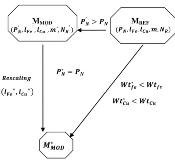
Revisiting the similarity law (18) and adopting differentiated scales for copper and iron, 𝒍𝒍𝑪𝑪𝒖𝒖 and 𝒍𝒍𝑭𝑭, keeping the flux density and the variation temperature constant, the rated power is expressed by the relationship (19), as detailed by the authors in [13]. As illustrated in the diagram of Fig. 7, and having in mind a modular machine of equal power (𝑷𝑷𝑵𝑵′) to the regular machine (𝑷𝑷𝑵𝑵), the proportion of power values presented in Table I enables to infer the following rescaling relationships (20) and (21). 𝑷𝑷𝑵𝑵∝ 𝒎𝒎𝑵𝑵𝑹𝑹𝝎𝝎𝑩𝑩𝟐𝟐𝒍𝒍𝑭𝑭𝟑𝟑 (19) 𝑷𝑷𝑵𝑵′ 𝑷𝑷𝑵𝑵∝ 𝒎𝒎′𝑵𝑵 𝑹𝑹′ 𝒎𝒎𝑵𝑵𝑹𝑹 � 𝒍𝒍𝑭𝑭′ 𝒍𝒍𝑭𝑭� 𝟑𝟑 (20) 𝒍𝒍𝑭𝑭′ ∝ �𝟏𝟏, 𝟓𝟓𝟓𝟓 𝟏𝟏 𝒎𝒎𝒎𝒎𝑵𝑵′𝑵𝑵𝑹𝑹 𝑹𝑹′� 𝟏𝟏/𝟑𝟑 𝒍𝒍𝑭𝑭∝ 𝟎𝟎, 𝟖𝟖𝟐𝟐 𝒍𝒍𝑭𝑭 (21)
The rescaling operation shown in Fig. 7, consists on the reduction for identical rated power, in proportional terms, of the modular machine (MMOD) characteristic dimensions comparing to the regular machine (MREF). The rescaling operation is performed on an identical rated power basis. After performing the rescaling it is well-timed to establish relationships for both weight of iron 𝑾𝑾𝑾𝑾𝑭𝑭∗ and the weight of copper 𝑾𝑾𝑾𝑾𝑪𝑪𝒖𝒖∗ . The iron weight and the copper weight of the modular topology are compared with the SRG prototype as indicated by (22) and (23). 𝑾𝑾𝑾𝑾𝑭𝑭∗ ∝(𝒍𝒍𝑭𝑭 ∗)𝟑𝟑 (𝒍𝒍𝑭𝑭)𝟑𝟑 𝑾𝑾𝑾𝑾𝑭𝑭∝ 𝟎𝟎, 𝟓𝟓𝟓𝟓 𝑾𝑾𝑾𝑾𝑭𝑭 (22) 𝑾𝑾𝑾𝑾𝑪𝑪𝒖𝒖∗ ∝(𝒍𝒍𝑪𝑪𝒖𝒖 ∗)𝟑𝟑 (𝒍𝒍𝑪𝑪𝒖𝒖)𝟑𝟑 𝑾𝑾𝑾𝑾𝑪𝑪𝒖𝒖 ∝ (𝒍𝒍𝑭𝑭∗)𝟐𝟐 (𝒍𝒍𝑭𝑭)𝟐𝟐 𝑾𝑾𝑾𝑾𝑪𝑪𝒖𝒖∝ 𝟎𝟎, 𝟓𝟓𝟔𝟔 𝑾𝑾𝑾𝑾𝑪𝑪𝒖𝒖 (23)
In regards to this modular topology, the iron weight is approximately 55% of the regular topology, thus reducing the volume taken by the iron by 45%. In terms of copper weight it allows a reduction of 33% in respect to the regular 12/16 SRG. In terms of specific power, expressed in W/Kg, it is predicted that there will be an increase of power of 80% at the modular SRG per unit of iron mass, and an increase of close to 50% per unit of copper mass, when compared to the regular SRG.
𝐦𝐦 𝑵𝑵𝑹𝑹 𝝉𝝉𝑹𝑹 [𝒓𝒓𝒂𝒂𝒅𝒅] 𝜷𝜷𝑹𝑹 [𝒓𝒓𝒂𝒂𝒅𝒅] P (p.u)
Regular 12/16 prototype 3 16 𝟐𝟐/𝟖𝟖 𝟐𝟐/𝟐𝟐𝟒𝟒 1 Modular SFP topology 4 14 𝟐𝟐/𝟔𝟔 𝟐𝟐/𝟏𝟏𝟖𝟖 1,56
TABLE I. PARAMETERS OF THE COMPARED TOPOLOGIES
(𝑷𝑷𝑵𝑵′, 𝒍𝒍𝑭𝑭𝒆𝒆′, 𝒍𝒍𝑪𝑪𝒖𝒖′, 𝒎𝒎´, 𝑵𝑵𝑹𝑹′)
M
MOD (𝑷𝑷𝑵𝑵, 𝒍𝒍𝑭𝑭𝒆𝒆, 𝒍𝒍𝑪𝑪𝒖𝒖, 𝒎𝒎, 𝑵𝑵𝑹𝑹)M
REF 𝑷𝑷𝑵𝑵′ > 𝑷𝑷𝑵𝑵 𝑹𝑹𝒆𝒆𝑹𝑹𝒄𝒄𝒂𝒂𝒍𝒍𝒊𝒊𝑹𝑹𝒈𝒈 𝑾𝑾𝑾𝑾𝑪𝑪𝒖𝒖∗ < 𝑾𝑾𝑾𝑾𝑪𝑪𝒖𝒖(
𝒍𝒍𝑭𝑭𝒆𝒆∗,
𝒍𝒍𝑪𝑪𝒖𝒖∗)
𝑷𝑷𝑵𝑵∗ = 𝑷𝑷𝑵𝑵𝑴𝑴
𝑴𝑴𝑴𝑴𝑴𝑴∗ 𝑾𝑾𝑾𝑾𝒇𝒇𝒆𝒆∗ < 𝑾𝑾𝑾𝑾𝒇𝒇𝒆𝒆Fig. 7 – Schematic diagram of the rescaling operation for weight comparison purposes.
IV. CONCLUSION
This paper introduces a methodology built on field-based models for SR-machines dimensional analysis.
A comparative analysis has been presented for low speed SR machines. The comparison and evaluation of magnetic topologies plays an important role in low speed SR machines design. General design methodologies are usually oriented towards the evaluation of stator/rotor poles combinations for regular switched reluctance machines. Besides covering that feature, the field-based model proposed together with a proper formulation of scale laws, are also suitable to compare non-regular SR topologies. Taking into account thermal changes and magnetic saturation by introducing some constraints, a dimensional analysis was used to compare a non-regular topology with a regular topology: a modular short flux-path topology versus a regular low speed prototype SRG designed for a direct drive wind turbine. The modular topology can diminish the specific weight of the generator in the overall system, taking benefits from the significant gain of power per unit of mass.
This work does not aim to address a detailed design of a novel SRG, but rather highlight the usefulness and effectiveness of the field-based models acting together with similarity laws, as an assistant tool for this machine design. Furthermore, its application to regular and non-regular SR topologies clearly emphasizes some design details of magnetic structures in machine performance. Ultimately, in the field of direct drive energy converters and other low speed renewable energy systems, this field-based methodology helps the designer to achieve a SRG design with a minimum of trial-and-error sizing, when comparing different feasible SRG topologies.
ACKNOLEDGMENT
The authors would like to thank the Polytechnic Institute of Setúbal and FCT /New University of Lisbon for providing facilities during this research work.
REFERENCES
[1] X. Liu, K. Park, Z. Chen, "A Novel Excitation Assistance Switched Reluctance Wind Power Generator", IEEE Transactions on Magnetics, Vol.50, no.11, pp.1-4, Nov. 2014.
[2] I. Boldea, L. Tutelea, F. Blaabjerg, “High power wind generator designs with less or no PMs: an overview”, Proceedings of 17th International
Conference on Electrical Machines and Systems (ICEMS), Hangzhou,
China, Oct. 2014.
[3] T.J.E Miller, Switched Reluctance Motors and Their Control, Magna Physics Publishing and Clarendon Press, 1993.
[4] I. Kioskeridis, C. Mademlis., “Optimal Efficiency Control of Switched Reluctance Generators”, IEEE Trans. on Power Electronics, vol. 21, No.4, July 2006.
[5] P. Chancharoensook, M.F. Rahman, "Control of a four-phase switched reluctance generator: experimental investigations", Proc. of the IEEE
International Electric Machines and Drives Conference, vol.2,
pp.842-848, June 2003.
[6] R. Cardenas , R. Pena , M. Perez , J. Clare , G. Asher and P. Wheeler, "Control of a switched reluctance generator for variable-speed wind energy applications", IEEE Trans. on Energy Conversion, vol. 20, no. 4, pp.781 -791, 2005.
[7] B. Bilgin, A. Emadi, M. Krishnamurthy, "Design Considerations for Switched Reluctance Machines With a Higher Number of Rotor Poles",
IEEE Trans. on Industrial Electronics, vol.59, no.10, pp.3745-3756,
Oct. 2012.
[8] X. Liu, K. Park, Z. Chen, "A Novel Excitation Assistance Switched Reluctance Wind Power Generator", IEEE Transactions on Magnetics, Vol.50, no.11, pp.1-4, Nov. 2014.
[9] X.D. Xue, K.W.E. Cheng, Y.J. Bao, P.L. Leung and N. Cheung, " Switched Reluctance Generators with Hybrid Magnetic Paths for Wind Power Generation", IEEE Transactions on Magnetics, Vol.48, no.11, pp.3863-3866, Nov. 2012.
[10] Marcel Jufer, “Electric Drive: Design Methodology”, Wiley-ISTE press, 2013.
[11] M.A. Mueller, “Design and performance of a 20 kW, 100 rpm, switched reluctance generator for a direct drive wind energy converter”, Proc. of
the IEEE International Conference on Electric Machines and Drives,
San Antonio, Texas, U.S.A., pp. 56-63, 2005.
[12] M. Ruba, I. Bentia, L. Szabo, "Novel modular fault tolerant switched reluctance machine for reliable factory automation systems", Proc. of
2010 IEEE International Conference on Automation Quality and Testing Robotics (AQTR) , vol. 3, pp. 1-6, May 2010.
[13] P. Lobato, J.A. Dente, J.F. Martins, A.J. Pires, "Short flux-paths in switched reluctance generators for direct drive wind energy converters”,
Proc. of 9th International Conference on Compatibility and Power