Abstract—A compact broadband millimeter wave antenna for
intelligent transportation (ITS) application is proposed in this paper. This antenna uses coplanar wave guide feeding technique for broad bandwidth. The proposed antenna works at 79 GHz resonant frequency having a large bandwidth of 78.2 GHz. The measured gain of the antenna is 17.5 dBi. The proposed antenna is very suitable for short range radar (SRR) application and %G technologies.
Index Terms— Millimeter wave, ultra wide band, coplanar waveguide,
defected ground, short range radar.
I. INTRODUCTION
Intelligent transportation system (ITS) is important part of human life and country. It supports
human economy and helps in easily running of country. ITS have many applications lies in
millimeter-wave frequency range like automotive radar applications and enabling wireless
technologies. Automotive radar application is divided into two part like long range radar (LRR) and
short range radar (SRR). Short range radar (SRR) system is a crucial element in automobile safety. It
is responsible for detection and prevention of potential collisions. Thus, helps in reducing the number
and severity of road accidents. It has many more applications like, pre crash sensing / control firing of
restraints, airbags / break boosting, stop and go functionality, lane change warning, lane change aid,
blind spot detection, parking aid and back drive assistance [1] [2]. Fig.1 shows the coverage area of
automotive radar antenna. Short range radar has four types: continuous wave (CW) radar, frequency
modulated continuous wave (FMCW) radar, synthetic aperture radar (SAR), phased array radar, and
ultra wide band (UWB) impulse radar. Small CW Doppler radar systems are used as motion sensors
and for measuring the speed of automobiles. FMCW radar is used for radar altimeters in aircrafts.
SAR is developed for airborne ground mapping at a stand-off distance. Phased array radar is used for
imaging system. The millimeter wave antenna is used for short range radar application [3]. The SRR
for automotive application has three centre frequencies – 24.5 GHz, 26.5 GHz, and 79 GHz. Their
respective bandwidths are 5 GHz, 4 GHz, and 4 GHz respectively [4]. 5G is one the enabling
technologies that works in millimeter-wave frequency range. It works in the frequency range of 24
GHz to 86 GHZ [5].
This paper focuses on design and development of millimeter wave antenna for intelligent
Millimeter Wave Antenna for Intelligent
Transportation Systems Application
N. Kishore, G. Upadhyay, A. Prakash, V. S. Tripathi
Department of Electronics & Communication Engineering, Motilal Nehru national Institute of Technology Allahabad, U.P., India
Brazilian Microwave and Optoelectronics Society-SBMO received 04 Nov2017; for review 09 Nov 2017; accepted 13 March 2018
transportation systems (ITS) application. This paper focuses on the safety and connectivity
applications of vehicles. For safety application 79 GHz is the centre frequency [6] and for
connectivity 5G technologies used.
A 79GHz millimeter wave automotive radar front–end with monolithic microwave integrated
circuit (MMIC) technology having bandwidth of 9.05GHz and gain of 6.5dBi is discussed in [7]. A
79GHz millimeter wave antenna based on a conformal waveguide with slot array having 15.7 dBi
gain is discussed in [8]. A 77 GHz frequency modulated continuous-wave (FMCW) radar system
having bandwidth of 6 GHz and gain of 10 dBi is discussed in [9].
Fig. 1. Placement and coverage area of automotive radar antenna [10].
A 79 GHz patch antenna array for short range radar system having bandwidth of 9.6 GHz and gain
of 14.5 dBi is discussed in [11]. A 77 GHz electronically beam-steerable integrated lens millimeter
wave antenna having bandwidth of 35 GHz is discussed in [12]. A 77 GHz Yagi–Uda antenna for
automotive radar sensor having gain of 15.8 dBi is discussed in [13]. A 77 GHz and 94 GHz
millimeter wave radar system having bandwidth of 2 GHz and 4.9 GHz respectively is discussed in
[14]. A 77 GHz multi-channel directional folded dipole radar antenna having gain of 8.2dBi is
discussed in [15]. A 77 GHz lens antenna for automotive radar having bandwidth of 4GHz is
proposed in [16]. A 77 GHz millimeter wave technology for automotive radar sensors having
bandwidth of 4 GHz and half power beam width gain of 5 dBi is discussed in [17]. A 77 GHz
micro-electromechanical systems based active phase shifter for W–band automotive radar having gain of 14
dBi is proposed in [18]. A 76–77GHz radar having gain of 14.2 dBi is discussed in [19]. A microstrip
grid array antenna for millimeter wave frequencies having centre of 60 GHz and bandwidth of 5 GHz
with gain 14 dBi is reported in [20]. A 60 GHz printed millimeter array antenna for millimeter wave
application is discussed in [21]. A cavity back antenna works in frequency range of 28 GHz to 60
GHz for millimeter wave application is discussed in [22]. A substrate integrated dielectric resonator
antenna having centre frequency for millimeter wave application is reported in [23]
These antennas have relatively lower bandwidth and gain. In this paper, an antenna with very large
bandwidth and high gain is proposed. A novel antenna design is proposed based on defected ground
structure. Optimization is done to get best design parameters for proposed antenna. It is also circularly
polarized and hence, it can be used as millimeter wave antenna for short range radar application. The
simulation and experimental methods. The Simulated and experimental results match very well.
This paper is organized as follows: section II shows design specifications of proposed antenna.
Section III shows simulation result and discussion. The conclusion is presented in section IV.
II. DESIGN SPECIFICATION
In this section we discuss the structure of proposed antenna and its design procedure. In order to get
high centre frequency the size of the antenna should be small and dielectric constant of substrate
should be high. In proposed antenna design coupling of energy between the coplanar wave guides
feed line and square patch yields resonance at desired centre frequency. Further, the energy coupling
between coplanar wave guide feed line and defected ground structure results in a very large
bandwidth.
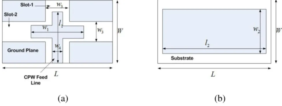
The structure of proposed antenna is shown in Fig.2. The top view of the proposed antenna
structure is shown in Fig.2 (a).
(a) (b)
Fig. 2 Proposed antenna structure shows (a) top view and (b) bottom view.
The top view of the proposed antenna structure shows the defected ground plane with CPW feed
line in Fig.2 (a). There are two slots in the ground plane each having width w3. The length of the feed
line is l1 and its arm length is w1. The width of the feed line is w4. Bottom view shows copper plane in
Fig.2 (b) having dimension of l2 × w2. The substrate material used is Roger 3210 having dielectric
constant 10.2 with height 1.28 mm. The length and width of substrate are L and W respectively. The
antenna is simulated using HFSSv18 [24]. The values of parameters are given in Table I.
TABLE I.VALUES OF PARAMETERS (IN MM)
Parameter L W l1 w1 l2 w2 w3 w4
Value 24 14 11 8 18 10 4 2
III. RESULT AND DISCUSSION
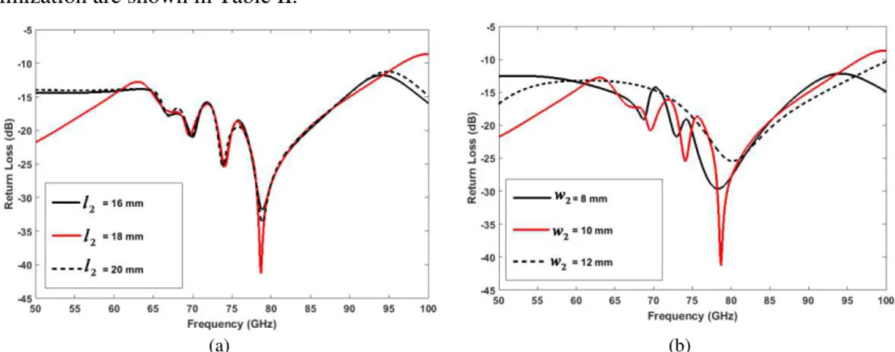
Fig.3 shows the simulated result of return loss by varying the length and width of the patch of
proposed antenna structure. Fig.4 shows the simulated result of return loss by varying the parameters
of feed line and ground slots. The results are shown in Table II.
It shows the parametric analysis of proposed antenna structure. From parametric analysis the values
Brazilian Microwave and Optoelectronics Society-SBMO received 04 Nov2017; for review 09 Nov 2017; accepted 13 March 2018
optimization are shown in Table II.
(a) (b)
Fig. 3. Simulated return loss in dB by (a) variation in length of bottom plane l2 and (b) variation in width of bottom plane w2.
(a) (b)
(c)
Fig. 4. Simulated return loss in dB by (a) variation in length of feed line l1, (b) variation in length of arm of feed line w1 and (c) variation in width of slots of the ground plane w2.
TABLE II.RETURN LOSS RESULTS DATA BY VARYING PARAMETERS
Parameter Values (in mm)
Centre Frequency (in GHz)
Return loss (in dB)
Bandwidth below -20dB return loss (in GHz)
l1
10 81.3 -27.27 10
11 79 -41.29 8.1
12 79.1 -33.37 8.7
w1
6 78.8 -42.78 8.2
8 79 -41.29 8.1
10 78.8 -34.8 8.2
18 79 -41.29 8.1
20 78.9 -33.68 8.2
w2
8 78.3 -29.64 10.1
10 79 -41.29 8.1
12 80.2 -25.44 9.6
w3
3 78.1 -27.08 2
4 79 -41.29 8.1
5 78.6 -40.09 7.4
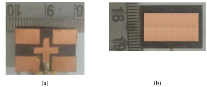
The prototype of antenna is shown in Fig.5. The proposed antenna structure is fabricated and tested
in the laboratory. The prototype antenna is connected with keysight 11500J test port cable and tested
with keysight N5250A-017 PNA millimeter-wave network analyzer. The simulated and measured
results for return loss are shown in Fig.6. It is noted that the measured and simulated results match
very well. The observed centre frequency is 79 GHz. The measured value of the return loss is -40.9
dB. The measured bandwidth is 78.2 GHz below -10 dB return loss having band range of 18.1 GHz –
96.3 GHz.
(a) (b)
Fig. 5. Prototype of proposed antenna shows (a) top view and (b) bottom view
Fig. 6. Simulated and measured result of return loss of the proposed antenna structure.
The vector current distribution of proposed antenna is shown in Fig.7. This figure shows that there
is energy coupling between the feed line and the defected ground structure. This coupling of energy
produces very low value of capacitance and inductance of the antenna. The low value of capacitance
Brazilian Microwave and Optoelectronics Society-SBMO received 04 Nov2017; for review 09 Nov 2017; accepted 13 March 2018
feed line and bottom plane. This helps in the impedance matching, which in turn produces the desired
centre frequency. Due to coupling, this antenna produces a very wide bandwidth
Fig. 7. Current distribution on the proposed antenna structure.
.
(a) (b)
Fig. 8. Simulated and measured result of radiation pattern (a) E plane, and (b) H plane
The simulated and measured radiation pattern results are shown in Fig.8. The simulated and
measured results of E Plane and H Plane are shown in Fig.8. It can be observed that E plane radiation
of proposed antenna covers broad range while H plane has less backward radiation and covers small
range with high gain value.
The proposed antenna produces high gain as shown in Fig.9. The simulated and measured gains of
the antenna are 19.46 dBi and 17.5 dBi respectively. This shows that antenna is suitable for
automotive radar system.
TABLE III.COMPARISON OF RECENTLY PUBLISHED WORK ON MILLIMETER WAVE ANTENNA WITH PROPOSED WORK
Parameter
Abdellatif et.al.
2015 [11]
You Chao Tu et.al.
2016 [25]
Yujian Li et.al.
2017 [26] Proposed Work
Centre Frequency 79 GHz 35 GHz 34 GHz 79 GHz
Bandwidth 9.6 GHz 8.75 GHz 13.5 GHz 78.2 GHz
Gain 14.5 dBi 4.6 dBi 13.6 dBi 17.45 dBi
Further, a comparison of results of proposed work with newly reported antenna is shown in Table
III. It is noted that the proposed antenna gives better result than the reported antenna. The proposed
antenna is suitable for SRR in ITS applications.
IV. CONCLUSION
The proposed antenna gives a very wide band range of 18.1 GHz to 96.3 GHz. The measured
bandwidth of proposed antenna structure is 78.2 GHz. The proposed antenna is circularly polarized in
nature. In this paper parametric analysis of proposed antenna is also discussed. The measured and
simulated results match very well. The prototype of antenna has very high gain of 17.5 dBi. High
gain, large and bandwidth of antenna make it suitable for intelligent transportation application.
REFERENCES
[1] R. Bishop, “Application Areas”,in Intelligent Vehicle Technology and Trends, Artech House ITS Library, pp. 25 - 37, 2005.
[2] R. Lachner, “Development Status of Next Generation Automotive Radar in EU”, ITS Forum , Tokyo, 2009. [3] G. L. Charvat, “Small and Short-Range Radar Systems”, CRC Press, 2014.
[4] A. Kajiwara, “UltraWideband Automotive Radar”,in Advances in Vehicular Networking Technologies, pp. 103 - 122, 2011.
[5] https://www.rfpage.com/applications-of-millimeter-waves-future/ (Date-05/02/2018)
[6] ITU-R WP 5A/B, “Intelligent transport systems (ITS)”, Radiocommunication Study Groups, International Telecommunication Union, 2015.
[7] D. Platt, L. Pettersson, D.Jakonis et al. “Integrated 79GHz UWB Automotive Radar Front– End based on Hi–Mission MCM–D Silicon Platform”, Proceedings of the 6th European Radar Conference, pp. 445 - 448, 2009.
[8] H. Iwai, S.Suetsugu et al., “Feasibility Study on a Slot Array in the Millimeter–Wave Band Based on a Conformal Waveguide”, International Symposium on Antennas and Propagation (ISAP),vol. 5, pp. 1– 3, 2015.
[9] A. Melzer, A. Onic, F. Starzer,and M. Huemer, “ShortRange Leakage Cancelation in FMCW Radar Transceivers Using an Artificial On- Chip Target”, IEEE Journal of Selected Topics in Signal Processing, vol. 9, no. 8, pp. 1650 – 1660, 2015.
[10]Jau–Jr Lin, “Analysis and Design of the Switched-beam Antenna Array for Automotive Radar Applications”, Progress In Electromagnetics Research Symposium Proceedings, pp. 2561 - 2564, 2014.
[11]A. Abdellatif, M. Ghassemi et al., “Low Cost Low Loss Waveguidefed Patch Antenna Array for Automotive Radar System”, Global Symposium on Millimeter Waves (GSMM), pp. 1 – 3, 2015.
[12]A. Artemenko, A. Mozharovskiy et al., “Experimental Characterization of E-Band Two-Dimensional Electronically Beam–Steerable Integrated Lens Antennas”, IEEE Antennas and Wireless Propagation Letters, vol. 12, pp. 1188 - 1191, 2013.
[13]S. Beer, G. Adamiuk,and T. Zwick, “Novel Antenna Concept for Compact Millimeter-Wave Automotive Radar Sensors”, IEEE Antennas and Wireless Propagation Letters, vol. 12, pp. 771 – 774, 2009.
[14]G. M. Brooker, “Mutual Interference of Millimeter-Wave Radar Systems”, IEEE Transactions on Electromagnetic Compatibility, vol. 7, no. 1, pp. 170 – 181, 2007.
[15]A. Fischer, Z. Tong et al., “77–GHz Multi-Channel Radar Transceiver With Antenna in Package”, IEEE Transactions on Antennas And Propagation, vol. 62, no. 3, pp. 1386 - 1393, 2014.
Brazilian Microwave and Optoelectronics Society-SBMO received 04 Nov2017; for review 09 Nov 2017; accepted 13 March 2018 [17]J. Hasch, E. Topak et al., “Millimeter-Wave Technology for Automotive Radar Sensors in the 77 GHz Frequency
Band”, IEEE Transactions on Microwave Theory and Techniques, vol. 60, no. 3, pp. 845 - 860, 2012.
[18]E. Ozturk, M. H.Nemati et al., “SiGe Process Integrated Full360 Microelectromechanical SystemsBased Active Phase Shifter for W-Band Automotive Radar”, IET Microwaves, Antennas and Propagation, pp. 835 - 841, 2014.
[19]M. Chen, C. C. Chen, S. Y. P. Chien, and R. Sherony, “Artificial Skin for 76-77 GHz Radar Mannequins”, IEEE Transactions on Antennas and Propagation, vol. 62, no. 11, pp. 5671 - 5679, 2014.
[20]B. Zhang and Y. P. Zhang, “Analysis and Synthesis of Millimeter-Wave Microstrip Grid-Array Antennas”, IEEE Antennas and Propagation Magazine, vol. 53, no. 6, pp. 42 – 55, December 2011.
[21]Aleksandar D. Nesic and Dusan A. Nesic, “Printed Planar 8x8 Array Antenna with Circular Polarization for Millimeter -Wave Application”, IEEE Antennas and Wireless Propagation Letters, vol. 11, pp. 744 – 747, 2012.
[22]Shi-Wei Qu and Kung Bo Ng, “Millimeter-Wave Bowtie Excited Cavity-Backed Antenna with Improved Aperture”,
IEEE Antennas and Wireless Propagation Letters, vol. 11, pp. 697 – 700, 2012.
[23]Abdolmehdi Dadgarpour, Behnam Zarghooni, Bal S.Virdee, and Tayeb A.Denidni, “Millimeter-Wave High-Gain SIW End-Fire Bow-tie Antenna”, IEEE Transactions on Antennas and Propagation, vol. 63, no. 5, pp. 2337 – 2342, May 2015.
[24]ANSYS Academic Research, Release 15.0.
[25]You Chao Tu, Dong Dong Ma, Yan Liu, Xue Rui Ru, and Ke Gong, “Broadband Substrate Integrated Dielectric Resonator Antenna for Millimeter-Wave Applications”, IEEE MTT-S International Microwave Workshop Series on Advanced Materials and Processes for RF and THz Applications (IMWS-AMP), pp. 1 – 3, 20-22 July 2016.
![Fig. 1. Placement and coverage area of automotive radar antenna [10].](https://thumb-eu.123doks.com/thumbv2/123dok_br/16310029.718294/2.892.311.580.343.504/fig-placement-coverage-area-automotive-radar-antenna.webp)