c
Copernicus GmbH 2003
Advances in
Radio Science
Planar millimeter wave radar frontend for automotive applications
J. Grubert1, J. Heyen1, C. Metz2, L. C. Stange1, and A. F. Jacob1
1Institut f¨ur Hochfrequenztechnik, Technische Universit¨at Braunschweig, Postfach 3329, 38023 Braunschweig, Germany 2Network Hardware Integration Research Department, Bell Laboratories, Murray Hill, NJ 07974, USA
Abstract. A fully integrated planar sensor for 77 GHz automotive applications is presented. The frontend consists of a transceiver multichip module and an electronically steerable microstrip patch array. The antenna feed network is based on a modified Rotman-lens and connected to the array in a multilayer approach offering higher integration. Furthermore, the frontend comprises a phase lock loop to allow proper frequency-modulated continuous wave (FMCW) radar operation. The latest experimental results verify the functionality of this advanced frontend design featuring automatic cruise control, precrash sensing and cut-in detection. These promising radar measurements give reason to a detailed theoretical investigation of system performance. Employing commercially available MMIC various circuit topologies are compared based on signal-to-noise considerations. Different scenarios for both sequential and parallel lobing hint to more advanced sensor designs and better performance. These improvements strongly depend on the availability of suitable MMIC and reliable packaging technologies. Within our present approach possible future MMIC developments are already considered and, thus, can be easily adapted by the flexible frontend design.
Es wird ein integrierter planarer Sensor f¨ur 77 GHz Radaranwendungen vorgestellt. Das Frontend besteht aus einem Sende- und Empfangs-Multi-Chip-Modul und einer elektronisch schwenkbaren Antenne. Das Speisenetzwerk der Antenne basiert auf einer modifizierten Rotman-Linse. F¨ur eine kompakte Bauweise sind Antenne und Speisenetzwerk mehrlagig integriert. Weiterhin umfasst das Frontend eine Phasenregelschleife f¨ur eine pr¨azise Steuerung des frequenzmodulierten Dauerstrichradars. Die aktuellen Messergebnisse best¨atigen die Funktionalit¨at dieses neuartigen Frontend-Designs, das automatische Geschwindigkeitsregelung, Kollisionswarnung sowie Nahbereichs¨uberwachung erm¨oglicht. Die Qualit¨at der
Correspondence to:J. Grubert ([email protected])
Messergebnisse hat weiterf¨uhrende theoretische Unter-suchungen ¨uber die potenzielle Systemleistungsf¨ahigkeit motiviert. Unter Ber¨ucksichtigung von kommerziell erh¨altlichen MMICs werden verschiedene Schaltungstopolo-gien auf der Grundlage des Signal-Rausch-Verh¨altnisses verglichen. Sowohl f¨ur sequenzielle als auch f¨ur parallele Ansteuerung der Antennenkeulen wird eine deutliche Leis-tungssteigerung ermittelt. Diese Verbesserungen h¨angen maßgeblich von der Verf¨ugbarkeit geeigneter MMICs und einer zuverl¨assigen Aufbau- und Verbindungstechnik ab. Das vorliegende Frontend-Konzept kann auf Grund seiner Flexibilit¨at leicht an derlei zuk¨unftige Entwicklungen angepasst werden.
1 Introduction
Modern automobiles are equipped with an increasing number of electronic assistance systems to support the driver. In this context automotive radars gained a lot of interest in the past. This paper reports on a frequency modulated continuous wave (FMCW) sensor, which consists of a planar antenna, millimeter-wave monolithic integrated circuits (MMIC), and a phase locked loop (PLL). Printed circuit board technology and usage of MMIC offer fundamental advantages for sys-tem integration and mass production. Because of the fast progress of the MMIC performance a flexible sensor concept is useful to quickly integrate new chip sets.
2 Prototype of the frontend
2.1 Antenna
-80 -60 -40 -20 0 20 40 60 80 -50
-40 -30 -20 -10 0
radi
a
tion
pat
te
rn
/dB
azimuth angle /°
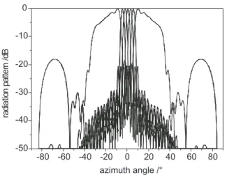
Fig. 1.Simulated RX-antenna pattern.
(H-plane). As shown in Fig. 1, the antenna system possesses five beams of 2.7◦width at 26.6 dBi average gain. The dis-tributed excitation for cut-in detection is designed to concen-trate the power to the array center region. Hence, the effec-tive array aperture is reduced, which results in a beam broad-ening.
The TX antenna illuminates permanently the entire field of view. With a half-power beamwidth of 22◦, the resulting radiation pattern exhibits a gain of 23 dB.
Both the RX- and the TX-antenna have columns of 31 series-fed patches which determine theE-plane characteris-tic. Each patch column is fed at its center element by aperture coupling.
2.2 Transceiver unit
Figure 2 illustrates the architecture of the transceiver unit in-cluding PLL and antennas (Jacob et al., 2002). A voltage-controlled oscillator (VCO) generates a 12.75 GHz sig-nal, which is amplified and tripled on-chip (CHV2242) to 38.25 GHz. The oscillator is coupled to a medium-Q res-onator consisting of three coupled half-wave lines, as sug-gested in (Camiade et al., 2000). The oscillator exhibits a free-running phase noise of−75 dBc/Hz @ 100 kHz and a tuning range exceeding 150 MHz.
The multifunction chip (CHU2277) combines a frequency doubler and amplifiers. It has two 76.5 GHz ports with an output power of 13 dBm and 9 dBm, respectively. These feed the TX antenna and the local-oscillator (LO) port of the receiving mixer, respectively.
The integrated in-phase and quadrature mixer (CHM2177) down-converts the signal of the receiving antenna for fur-ther signal processing. Sequential lobing of the seven RX-antenna beams is provided by means of p-i-n switch MMIC. Since single-chip 77 GHz SP7T p-i-n switches are currently not available, two W6P1 p-i-n switches (Putnam et al., 1997) had to be cascaded. Hereby, additional losses in the order of 9 dB are introduced to each receiving path.
2.3 PLL
In order to suppress VCO phase noise and improve frequency chirp linearity, it is essential to employ phase-lock techniques as a part of the radar synthesizer. An especially demanding requirement for the stepped FMCW approach is a short set-tling time in combination with small frequency steps (Mende and Rohling, 1997).
A direct digital synthesizer (DDS) is used as a reference source for the single-loop PLL. Usually the difficulty associ-ated with DDS is their high spurious signal content at higher output frequencies. To alleviate this, the DDS is operated at lower frequencies (4–9 MHz), where the spurious-free dy-namic range is sufficiently high. This output is up-converted, filtered, and fed to the phase/frequency detector (PFD), as shown in Fig. 2.
The VCO output at 38.25 GHz is partially coupled into the feedback path and down-converted by an integrated os-cillator/mixer MMIC (CHV2241). The output IF signal in the frequency range of 704–784 MHz is amplified and fed to the PFD through a prescaler/divider chain (N = 16) for comparison with the reference signal at 44–49 MHz.
Within 300 kHz around the carrier, the phase noise is effi-ciently suppressed by typically 10-15 dB, yielding a nominal value of−85 dBc/Hz @ 100 kHz. The transient behavior of the loop, determined by the loop filter bandwidth, is charac-terized by settling times of less than 1.5µs.
2.4 Assembly and test
A 630-µm-thick alumina substrate carries the RF-electronics consisting of four commercially available MMICs (Camiade et al., 2000), two MMIC p-i-n switches (Putnam et al., 1997), and various passive circuit components. While all RF con-nections are wire bonded, the DC and IF interconcon-nections are flip-chipped using conductive adhesives. The feed network is supported by a layer of Rohacell to avoid impairment of its electrical characteristics due to package influence.
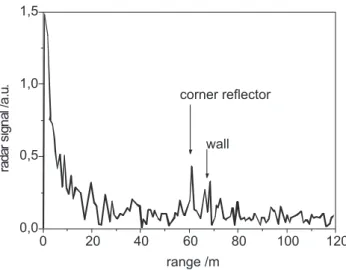
First functionality tests were conducted in a stationary en-vironment. The processed data is shown in Fig. 3. A cor-ner reflector located at 60 m and a wall at about 70 m are clearly visible. A more detailed description of the measure-ment setup can be found in (Metz et al., 2001a).
3 Advanced RF-circuit concepts
Figure 4 depicts different standard radar frontend concepts. These were analyzed similarly to (Jacob et al., 2002), but tak-ing into account recent MMIC developments (Camiade et al., 2002). They were compared with respect to maximum radar range. Other performance aspects as well as circuit complex-ity are briefly addressed in the following. The transmit and receive blocks, labeled T/R in Fig. 4, include the oscillator with its PLL as well as the receiving mixer, and are assumed to be identical in all cases.
~ x2
CHV 2241
DR Medium Q
Resonator ~= x3
CHV 2242 CHU 2277
x2
Coupler
: 16 PFD
Quartz
Oscillator LP
LP BP
W6P1
TX
RX CHM 2177
IQ DDS
Fig. 2.Block diagram of the sensor.
0 20 40 60 80 100 120 0,0
0,5 1,0 1,5
wall corner reflector
radar
s
ign
al
/a
.u.
range /m
Fig. 3.Measurement result with target at 60 m and wall at 70 m.
transmit and receive operation. In Figs. 4a and c the indi-vidual beams are represented by boxes labeled T/R X. The system is small but needs a diplexer to separate the RX-and TX-paths. In monolithic integrated system this device could be a hybrid which introduces losses. Bistatic systems use two distinct antennas for transmit and receive, labeled as TX and RX, respectively (see Figs. 4b and d). The diplexer and the associated loss can thus be avoided and the RX-/TX-decoupling is improved at the expense of the required space. The TX-antenna can further be designed to simultaneously illuminate the whole field of view. This could be advanta-geous in terms of signal-to-noise ratio.
The surveillance of a wider angular range with a given (fine) resolution can be achieved by either sequential or par-allel lobing. In the former case (Figs. 4 a and b) only one T/R-module is needed that must be sequentially connected to the different antennas by means of a multiplexer. Parallel lobing, in contrast, requires as many receivers as beams for simultaneous signal processing. Obviously, this saves time, an important feature in automotive applications. Also, the loss generally introduced by the multiplexer can be reduced. The drawback is the increased circuit complexity, i.e. the higher number of MMIC.
A comparison shows that the concept with best overall performance combines a bistatic antenna system and
paral-lel lobing. It provides good decoupling of the TX- and RX-paths, fast signal detection because of parallel data acquisi-tion, and large radar range because of lower losses. A pos-sible realization based on recently presented MMIC (Cami-ade et al., 2000, 2002) will therefore be discussed in more detail next. Figure 5 depicts a block diagram of a pos-sible configuration. From the sensor discussed in Sect. 2 and sketched in Fig. 2 only the integrated oscillator/mixer MMIC (CHV2241) and the multifunction chip (CHU2277) are kept. The VCO is replaced by the highly integrated ver-sion CHV2243. The output signal is amplified and partially coupled into the PLL-feedback path. The remainder is split to feed both the TX- and the LO-path. The former leads to the novel multifunction chip (CHU3077), which delivers a max-imum output power of 17 dBm. The latter is connected to the multifunction chip CHU2277. Its two output ports con-stitute the first stage of the multiplexer. Two active power splitters (CHA2177) in the second stage provide four LO-signals. These feed dual channel mixers (CHM2378) allow-ing to connect eight antenna ports. To improve the signal-to-noise ratio low signal-to-noise amplifiers (LNA) (CHA1077) are added in each RX-path.
4 Maximum radar range
To evaluate the system performance the frontend can be re-duced to the block diagram in Fig. 6. The two-ports exhibit overall gain (GT X,RX) and noise figure (FT X,RX) of the en-tire TX- and RX-path, respectively. They also take into ac-count loss and noise of the antennas. Their directivity is given byDT X andDRX, respectively, as shown in the Fig-ure. The LO-noise is not taken into account. The powerPRX echoed from a target of radar cross sectionAat distancer follows from the well-known radar equation (Skolnik, 1980). The signal-to-noise ratio(S/N )at the mixer output is then obtained as(S/N )=PRX/(FRXPN). Here,PN =kBTaB is the noise power received by the RX-antenna (B: band-width;kB: Boltzmann constant;Ta =290 K: assumed noise temperature). For given minimum detectable signal to noise ratio (S/N )min the maximum radar rangermax is obtained from:
rmax= 4 s
DT XDRXλ2PT XA (4π )3(S/N )
minFRXkBTaB
T R T R T R T/R X T/R X T/R X T/R X T/R X T/R X …
(c) parallel - monostatic (c) parallel - monostatic
T R T/R X T/R X T/R X T/R X T/R X T/R X …
(a) sequential - monostatic (a) sequential - monostatic
T X T X R X R X R X R X R X R X … … T R R R …
(d) parallel - bistatic (d) parallel - bistatic
T R T X T X R X R X R X R X R X R X …
(b) sequential - bistatic (b) sequential - bistatic
Fig. 4.Different concepts for RF-circuits.(a): Monostatic antenna and sequential processing.(b): Bistatic antenna and sequential processing.
(c): Monostatic antenna and parallel processing.(d): Bistatic antenna and parallel processing.
… T X T X R X R X … … x2 x3 Hi. Q Res. Hi. Q Res. PLL x2 x2 R X R X CHV2243 CHU3077 CHV2241 CHU2277 CHA2177 CHM2378 CHA1077
Fig. 5. Bistatic antenna and parallel processing system with latest chip generation. PTX PTX PO PO FTX FTX GTX GTX DTX
DTX r
A PRX PRX PN PN FRX FRX GRX GRX DRX DRX (S/N)
Fig. 6.Block diagram for the determination of the maximum radar range.
Here,λis the wavelength in free space. To estimate the radar range of the system in Fig. 5 the following assumptions were made. The attenuation of the bond wires and the transmit an-tenna reduce the output powerPO of the CHU3077 chip to PT X =15 dBm. The directivity of the TX- and RX-antenna are 27 dB and 36 dB, respectively. The losses of the RX-antenna are estimated to 10 dB. At the center frequency of 76.5 GHz the required signal bandwidth isB=150 kHz. A worst case target with a radar cross section ofA = 1 m2 is considered; this corresponds approximately to a pedes-trian. The characteristics of the RX-antenna (F = 10 dB, G = −10 dB), the LNA (F = 4 dB,G = 17 dB (Cami-ade et al., 2002)), and the mixer allow to calculate the cas-caded noise figure. The dependence of the mixer noise fig-ure on output frequency (IF) is taken as specified in (UMS, 2001). Figure 7 shows achievable radar ranges for configu-rations with varying numbers of LNA in the RX-paths and for two minimum signal-to-noise ratios(S/N )min. The left ordinate applies for(S/N )min = 10 dB, the right one for (S/N )min = 0 dB. The first configuration without LNA shows a maximum range which varies between 40 and 110 m
1 10 100
0 100 200 300 400 500 0 50 100 150 200 250
two LNA in Rx-path one LNA in Rx-path no LNA in Rx-path
m m a a x x i i m m u u m m r r a a n n g g e e ( ( ( ( S S / / N N ) ) m m i i n n = = 10 0 d d B B ) ) / / m m IF /kHz
Fig. 7. Maximum radar range of the system in Fig. 5 with
(S/N )min=10 dB and(S/N )min=0 dB.
(resp. 75 and 200 m) as a function of IF. Adding one LNA in each RX-path yields significant improvement with a max-imum range between 110 and 220 m (resp. 200 and 390 m). A second LNA also increases the range and further reduces the IF dependence. The achievable range now varies between 220 and 240 m (resp. 390 and 420 m).
In summary, an IF of 200 kHz and a LNA in each RX-path seems to be a good compromise in terms of system per-formance. Indeed, a small radar cross section such as from a pedestrian is detectable at 200 m even for (S/N )min = 10 dB.
5 Conclusions
References
Camiade, M., Domnesque, D., Quarch, Z., and Sion, A.: Fully MMIC-based front end for FMCW automotive radar at 77 GHz, Proc. 30th EuMC, Paris, France, pp. 9–12, 2000.
Camiade, M., Baglieri, D., Cortese, P., Domnesque, D., Sion, A., Beilenhoff, K., and Daembkes, H.: Monolithic microwave and MM-wave ICs for automotive applications – measures for cost reduction, IEEE MTT-S Int. Microwave Symp. Workshop Notes Automotive Radars & Prospective Circuit / Antenna Technolo-gies from “Car Collision Avoidance” to “Autonomous Driving”, Seattle, WA, 2002.
Jacob, A. F., Metz, C., Grubert, J., Heyen, J., and Stange, L. C.: Advanced Radar Concepts for Automotive Applications, IEEE MTT-S Int. Microwave Symp. Workshop Notes Automotive Radars & Prospective Circuit / Antenna Technologies from “Car Collision Avoidance” to “Autonomous Driving”, Seattle, WA, 2002.
Mende, R. and Rohling, H.: A high performance AICC radar
sen-sorconcept and results with an experimental vehicle, Radar’97, J¨arf¨alla, Sweden, pp. 21–25, 1997.
Metz, C., Grubert, J., Heyen, J., Jacob, A. F., Janot, S., Lissel, E., Oberschmidt, G., and Stange, L. C.: Fully integrated automotive radar sensor with versatile resolution, IEEE Trans. Microwave Theory Tech., 49, 12, pp. 2560–2566, Dec. 2001a.
Metz, C., Lissel, E., and Jacob, A. F.: Planar Multiresolutional An-tenna for Automotive Radar, Proc. 31st EuMC, London, UK, 1, pp. 335–338, 2001b.
Putnam, J., Barter, M., Wood, K., and LeBlanc, J.: A monolithic GaAs PIN switch network for a 77 GHz automotive collision warning radar, IEEE MTT-S Int. Microwave Symp. Dig., 2, pp. 753–756, 1997.
Skolnik, M. I.: Introduction to radar systems, McGraw-Hill Inc., 1980.