Pedro Alexandre Afonso Simão
Bachelor of Computer Science and EngineeringIoT Platforms for Building Automation with
Energy Efficiency and Comfort Concerns
Dissertation submitted in partial fulfillment of the requirements for the degree of
Master of Science in
Computer Science and Engineering
Adviser: Vasco Amaral, Assistant
Professor, Faculdade de Ciências e Tecnologia, Universidade Nova de Lisboa
Co-adviser: Jácome Cunha, Assistant
IoT Platforms for Building Automation with Energy Efficiency and Comfort Concerns
Copyright © Pedro Alexandre Afonso Simão, Faculdade de Ciências e Tecnologia, Univer-sidade NOVA de Lisboa.
A Faculty of Sciences and Technology e a NOVA University of Lisbon têm o direito, per-pétuo e sem limites geográficos, de arquivar e publicar esta dissertação através de exem-plares impressos reproduzidos em papel ou de forma digital, ou por qualquer outro meio conhecido ou que venha a ser inventado, e de a divulgar através de repositórios científicos e de admitir a sua cópia e distribuição com objetivos educacionais ou de investigação, não comerciais, desde que seja dado crédito ao autor e editor.
This document was created using the (pdf)LATEX processor, based in the “novathesis” template[1], developed at the Dep. Informática of FCT-NOVA [2].
Ac k n o w l e d g e m e n t s
A b s t r a c t
It is increasingly common to work and live in buildings controlled by some system, the so-called Building Automation Systems, where to keep the levels of comfort and reduce energy consumption are very important requirements. These systems control from heat-ing, ventilation, air conditionheat-ing, to lights intensity, with the goal of reducing energy costs and make the building occupants satisfied.
However, these systems are usually proprietary and have high costs associated, due to the required equipment to deal with all the devices and the distinct communications. Therefore, our goal is to reduce reduce these costs, which is quite difficult due to the vast devices heterogeneity.
In this dissertation, we implement a Building Automation System taking advantage of existingInternet of Things (IoT)solutions. Thus, this thesis explores howIoTsolutions can fit adequately into the scenario of building automation.
To validate our technological choices and evaluate the adequacy of the chosen middle-ware, we made use of an existing case study of a room with multiple components and an aquarium as a subsystem. We have compared differentIoTapproaches and their impact on the energy consumption and occupants comfort.
The results obtained helped us to realise that in fact there are several aspects that can be enhanced in order to reduce energy consumption and maintain occupants’ comfort. An initial investment in the implementation of these systems may involve different types of equipment and development effort to achieve the desired solution. However in long term, it is worth the effort and initial investment on these systems since they can actually reduce the energy consumption and guarantee good conditions for the room occupants.
R e s u m o
É cada vez mais comum trabalhar e viver em edifícios controlados por algum sistema, os chamados Building Automation Systems, onde manter os níveis de conforto e reduzir o consumo de energia são requisitos muito importantes. Estes sistemas controlam o aqueci-mento, ventilação, ar condicionado e intensidade das luzes, com o objetivo de reduzir os custos de energia e manter os ocupantes do edifício confortáveis.
No entanto, estes sistemas são normalmente proprietários e têm um grande custo associado devido ao equipamento necessário para lidar com todos os dispositivos e as diferentes comunicações. Portanto, em geral, o grande objetivo passa por minimizar este custo, sendo complicado devido à grande diversidade de dispositivos.
Nesta dissertação, implementamos um Building Automation System aproveitando as soluções existentes. Assim, esta tese explora como as soluções Internet of Things (IoT) podem adequar-se a um cenário de building automation.
Para validar as nossas escolhas tecnológicas e avaliar se o middleware escolhido é o mais adequado, usamos um caso de estudo existente de uma sala com vários componentes e um aquário como subsistema. Comparamos as diferentes abordagensIoTe o impacto que estas têm no consumo de energia e no conforto dos ocupantes.
Os resultados obtidos ajudaram-nos a perceber que de facto existem vários aspetos que podem ser melhorados de maneira a reduzir o consumo de energia mantendo o conforto dos ocupantes. Um investimento inicial na implementação destes sistemas pode envolver vários equipamentos e um esforço de desenvolvimento para atingir a solução desejada. No entanto, a longo termo vale a pena o esforço e o investimento inicial nestes sistemas, uma vez que estes conseguem de facto reduzir o consumo de energia e garantir boas condições de conforto para os ocupantes da sala.
C o n t e n t s
List of Figures xv
List of Tables xix
Glossary xxi
Acronyms xxiii
1 Introduction 1
1.1 Context and Description . . . 1
1.2 Challenges . . . 2
1.3 Problem Statement and Final Goals . . . 3
1.4 Expected Contributions . . . 3
1.5 Research Project . . . 4
1.6 Document Structure. . . 4
2 Background 7 2.1 Cyber-Physical System . . . 7
2.2 Internet of Things . . . 9
2.3 Building Automation System. . . 10
2.3.1 Architecture Levels . . . 10
2.3.2 Sensors, Actuators and Controllers . . . 11
2.3.3 Communication Networks . . . 11
2.3.4 Occupancy Detection . . . 12
2.4 Summary . . . 12
3 Case study 15 3.1 Overall Description . . . 15
3.2 Physical Setup . . . 16
3.3 Available Services . . . 18
3.3.1 Control and Monitor . . . 18
3.3.2 Lights. . . 18
3.4 Occupants Comfort . . . 18
4 State of the art of IoT platforms 21
4.1 Internet of Things Architectures . . . 22
4.2 Internet of Things Elements . . . 23
4.3 Internet of Things Platforms . . . 24
4.3.1 WSO2 IoT . . . 25
4.3.2 IBM Watson IoT . . . 26
4.3.3 ThingSpeak IoT . . . 26
4.3.4 Microsoft Azure IoT . . . 27
4.3.5 Amazon Web Service . . . 27
4.4 Comparison of Internet of Things Platforms . . . 28
4.4.1 Key concepts. . . 28
4.4.2 Data analytics . . . 29
4.4.3 Communication models . . . 30
4.4.4 Features . . . 32
4.4.5 Discussion . . . 33
4.5 Internet of Things Middleware. . . 34
4.6 Fog Computing . . . 35
4.7 Building Automation System enhanced by Internet of Things . . . 37
4.8 Summary . . . 38
5 Comparison Review 39 5.1 Devices Management . . . 40
5.2 Data Processing, Analytics and Events . . . 42
5.3 Application and User Management . . . 45
5.4 Discussion . . . 46
5.4.1 Comparison of WSO2 and IBM Watson platforms. . . 47
5.4.2 Comparison of Open-Source and PaaS . . . 50
5.5 Summary . . . 51
6 Conceptualisation and Implementation 53 6.1 Requirements Engineering . . . 53
6.1.1 Stakeholders . . . 54
6.1.2 Questionnaires . . . 54
6.1.3 User Stories . . . 54
6.1.4 Functional Requirements. . . 59
6.1.5 Non-Functional Requirements. . . 64
6.1.6 Requirements Tracing . . . 66
6.2 Detailed User Stories . . . 67
6.2.1 Device Management . . . 67
6.2.2 Occupant Comfort, Presence Detection and Suggestions . . . 70
CO N T E N T S
6.2.4 Notifications . . . 75
6.2.5 Aquarium . . . 77
6.3 Architecture . . . 78
6.3.1 Non-Functional Requirements Treatment . . . 78
6.3.2 Architecture Styles . . . 81
6.3.3 Architecture Views . . . 82
6.4 Implementation . . . 86
6.4.1 Automation . . . 87
6.4.2 Front-end. . . 98
6.4.3 Backup . . . 100
6.4.4 Devices Tool . . . 101
6.5 Summary . . . 103
7 Evaluation and Results 105 7.1 Questionnaire . . . 105
7.2 Environment luminosity and temperature . . . 108
7.3 Presence detection. . . 110
7.4 Energy Consumption . . . 115
7.4.1 Lights. . . 115
7.4.2 Monitor. . . 117
7.4.3 Coffee Machine . . . 118
7.4.4 Other equipment . . . 119
7.4.5 Energy cost. . . 119
7.5 Occupants’ opinion . . . 123
7.6 Summary . . . 125
8 Conclusion 127 8.1 Summary . . . 127
8.2 Contributions . . . 129
8.3 Limitations . . . 130
8.4 Future Work . . . 130
Bibliography 133
A Questionnaire 143
B Questionnaire 2 149
C Requirements Tracing 153
L i s t o f F i g u r e s
2.1 Cyber-Physical System model . . . 8
2.2 Relationship between CPS and IoT . . . 8
2.3 Internet of Things vision . . . 9
2.4 Building Automation System Architecture Level . . . 11
3.1 SmartLab simplified 2D model . . . 16
4.1 Internet of Things 5 Layer Architecture. . . 23
4.2 WSO2 architecture . . . 25
4.3 IBM Watson IoT architecture . . . 26
4.4 ThingSpeak IoT architecture . . . 27
4.5 Azure architecture . . . 27
4.6 Amazon WS architecture . . . 28
4.7 Device-to-Device communication model example . . . 30
4.8 Device-to-Cloud communication model example . . . 31
4.9 Device-to-Gateway communication model example . . . 31
4.10 Back-end data sharing communication model example . . . 32
4.11 Fog Computing . . . 37
5.1 Relationship between device type, model and the physical device . . . 40
5.2 WSO2 create device type . . . 41
5.3 IBM Watson create device type . . . 42
5.4 Data Analytics Workflow . . . 42
5.5 Application owner life cycle perspective . . . 45
5.6 Application consumer life cycle perspective . . . 46
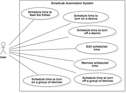
6.1 Use Case Diagram - Device Management . . . 68
6.2 Use Case Diagram - Occupant Comfort, Presence Detection and Suggestions 70 6.3 Use Case Diagram - Scheduling . . . 73
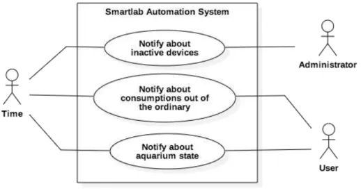
6.4 Use Case Diagram - Notifications . . . 75
6.5 Use Case Diagram - Aquarium . . . 77
6.6 Process proposal to handle NFRs . . . 79
6.8 Architecture Views - Sequence Diagram . . . 84
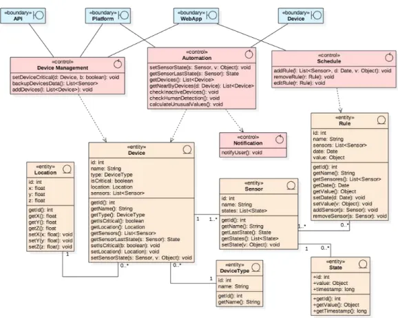
6.9 Architecture Views - Components Diagram . . . 85
6.10 Architecture Views - Deployment Diagram . . . 86
6.11 Node-Red Flow Example . . . 93
6.12 Power socket workday energy consumption example . . . 96
6.13 WebApp User Interface Flux Architecture . . . 99
6.14 Data Visualisation User Interface Example . . . 99
6.15 Backup Module Overview Diagram . . . 100
6.16 Device Tool Overview Diagram . . . 102
7.1 Important physical aspects . . . 106
7.2 Temperature satisfaction level . . . 106
7.3 Noise satisfaction level . . . 106
7.4 Luminosity satisfaction level . . . 106
7.5 Ventilation satisfaction level . . . 106
7.6 Preferable light source . . . 106
7.7 Lights state at morning . . . 107
7.8 Air condition system state at morning . . . 107
7.9 Notifications to open/close windows . . . 107
7.10 Coffee machine turned on at morning. . . 107
7.11 Luminosity level of a work station near the window . . . 108
7.12 Luminosity level of a work station near the window over a day . . . 109
7.13 Luminosity level of a work station away from the window over a day . . . 109
7.14 Temperature level of a work station near the window over a day . . . 110
7.15 Temperature level of a work station away from the window over a day . . . . 110
7.16 Occupant portable computer energy consumption . . . 111
7.17 Occupant monitor energy consumption . . . 112
7.18 Occupant presence detection through energy consumption . . . 113
7.19 Light power state behaviour . . . 113
7.20 Luminosity level of a work station . . . 114
7.21 Light brightness state behaviour . . . 114
7.22 Light 1 and Light 2 power state without automation . . . 115
7.23 Light 1 brightness state without automation . . . 115
7.24 Light 2 brightness state without automation . . . 116
7.25 Light 1 power state with automation . . . 116
7.26 Light 2 power state with automation . . . 117
7.27 Light 1 brightness state with automation . . . 117
7.28 Light 2 brightness state with automation . . . 117
7.29 Monitor energy usage without automation . . . 118
7.30 Monitor energy usage with automation . . . 118
L i s t o f F i g u r e s
7.32 Coffee machine energy usage with automation . . . 119
7.33 Devices daily usage hours with/without automation . . . 121
7.34 Devices energy cost per month with/without automation . . . 121
7.35 Coffee machine energy cost per month with/without automation . . . 122
7.36 Month energy cost with/without automation . . . 123
7.37 Occupant’s opinion . . . 124
7.38 System overall rating . . . 125
D.1 Front-end User Interface - Desktop view for devices types list . . . 157
D.2 Front-end User Interface - Desktop view for devices list . . . 158
D.3 Front-end User Interface - Desktop view for device details and control view . 158 D.4 Front-end User Interface - Desktop view for rules view . . . 159
D.5 Front-end User Interface - Mobile view for rules view . . . 159
D.6 Front-end User Interface - Mobile view for rule configuration view . . . 160
L i s t o f Ta b l e s
3.1 SmartLab physical components installed . . . 17
3.2 Fish tank equipped components . . . 17
4.1 Comparison of the key concepts of the studied platforms . . . 29
4.2 Comparison of data analytics tools provided by the studied platforms . . . . 30
4.3 Comparison of features provided by the studied platforms . . . 33
4.4 Fog comparison with cloud . . . 37
5.1 Platforms Comparison Overview . . . 52
6.1 User Management Mapping . . . 67
6.2 Handle Non-Functional Requirements (NFR) - Identify and Select NFR . . . 79
6.3 Handle NFR - Identify contributions between NFR . . . 80
6.4 Devices connected to sockets map . . . 89
6.5 Backup Module - Devices List example file . . . 101
6.6 Backup Module - Devices State example file . . . 101
6.7 Devices Tool - Input example file . . . 102
6.8 Devices Tool - Output example file . . . 103
7.1 Occupant card reader records . . . 111
7.2 Equipment energy consumption and cost per day . . . 121
7.3 Solution equipment list . . . 122
C.1 User Management Mapping . . . 153
C.2 API Management Mapping . . . 153
C.3 Device Management Mapping . . . 154
C.4 Occupant Comfort Mapping . . . 154
C.5 Presence Detection Mapping . . . 154
C.6 Scheduling Mapping . . . 155
C.7 Suggestions Mapping . . . 155
C.8 Notifications Mapping . . . 155
G l o s s a r y
Arduino Micro-controller used to build digital devices with capabilities to sense and control objects in the physical world.
Enterprise Service Bus Refers to an environment designed to promote interconnectivity between different services.
feedback loop Outputs of components serve as input as a part of chain of cause and effect.
Gateway Piece of networking hardware that interconnects networks with different net-work protocol technologies by performing the required protocol conversions.
Ac r o n y m s
API Application Program Interface.
ARP Address Resolution Protocol.
BAS Building Automation System.
BLE Bluetooth Low Energy.
CPS Cyber-Physical System.
CSV Comma Separated Values.
FR Functional Requirements.
HTTP Hypertext Transfer Protocol.
IaaS Infrastructure as a Service.
IoT Internet of Things.
JSON JavaScript Object Notation.
MQTT Message Queuing Telemetry Transport.
NFC Near Field Communication.
NFR Non-Functional Requirements.
OSGi Open Service Gateway Initiative.
PaaS Platform as a Service.
REST Representational State Transfer.
RFID Radio Frequency Identification.
UI User Interface.
UML Unified Modelling Language.
C
h
a
p
t
e
r
1
I n t r o d u c t i o n
This Chapter contains a brief introduction about the work developed in this dissertation. Section1.1briefly introduces a short description of BAS. Then, the challenges of implementing a Building Automation System (BAS)are presented (section1.2), followed by the problem statement and final goals (section1.3). We then lists the expected results of this dissertation (section1.4). Lastly, we present the global structure of this document (section1.6).
1.1 Context and Description
One of the concerns of computer science is the automation of tasks, whether for safety reasons (to make various tasks safer for humans) or for economic reasons (to increase productivity and efficiency). If we extend this concern to other domains such as Building Automation, we see a focus on the topic of reducing energy consumption.
In recent years, the way we use energy has changed because of the global environ-mental issues. For a sustainable development and a reduction of the impact that energy consumption has on the environment, it is necessary to resort to strategies that allow us to use resources more intelligently [SB15].
The biggest impact of the unintelligent use of energy lies in the larger buildings (industrial and service). Thus, the concept of BAS has emerged with the motivation of environmental safety and economic reasons.
BASsbegan by resolving the main part of energy waste in buildings: heating, venti-lation, and air conditioning systems. However, in commercial and residential buildings the light expenses should also be taken into consideration. [Ast+16].
(sensors), that provide data to the system. The system has the responsibility of interpret-ing the data provided by the sensors and sendinterpret-ing signals to other components installed with the capability of changing the desired state (actuators). Actuators are mechanisms responsible for turning on/offor changing intensity values of some device.
This setup has provided the concept of intelligent buildings, which can provide com-fort to the occupants, while efficiently maximise the use of energy. In this way, it is possi-ble to observe a reduction of energy consumption and consequently in its costs [Dom+16].
1.2 Challenges
Designing and implementing aBASis a complex process where several challenges can arise. Initially, it is important to analyse the environment where the system will act. Some-times it is possible to find some control system already implemented [Ast+16;Lea+14]. This makes it a challenge due to the closed, custom, lack of documentation, and property nature of these systems, which gives the equipment manufacturers full control over in-stallations and upgrades. Therefore, these systems have a high cost associated [Cor14; Ker+16;Tat16].
On the other hand, it is important to understand what kind of components are neces-sary to control and how the system will communicate with them. The system must take into account a vast heterogeneity of components available, and have the ability to deal with them. In this case, the challenge is to decide the most appropriate architecture that the system should adopt, considering all the components involved and future changes, in case it is necessary to support new components. [Dom+16].
There is a need to realise what entities will interact with the system and understand their roles and preferences. To engage the entities to help reducing energy costs, we can use techniques and mechanisms based on games (gamification). This will create conditions to stimulate the entities to take specific actions by making use of the hu-man psychological predisposition to engage in games. These techniques can encourage humans to complete tasks that would normally be tedious [Det+11]. However, having humans has a part of the system may cause some issues due to the complex psychological and behavioural aspect of humans [Mun+13].
The vast heterogeneity of devices is a problem for theBASs. There is no simple way to deal with this vast variety, so building owners need to choose equipment within the same range, which makes the price of these solutions higher [Dom+16].
1 . 3 . P R O B L E M S TAT E M E N T A N D F I N A L G OA L S
1.3 Problem Statement and Final Goals
Taking into account the challenges stated in section1.2, the goal of this dissertation is to provide a comparative analysis of the existingIoTplatforms for building automation with energy efficiency and comfort concerns.
Thus, the research question this dissertation intends to answer can be formulated as follows:
What are the concerns that should be taken into account, and appropriate software architecture for IoT solutions that can be used, to implement a BAS while ensuring low energy consumption and occupant comfort?
To understand the best solution to adopt based on existing work, we have analysed what are the key concepts an IoT platform should adopt in order to support the IoT paradigm. In Chapter4, we present a discussion on the several possible solutions based on their architecture. The most relevant aspects of each one take into account the case study described in Chapter3. However, for this thesis, we had the requirement that the solution should not be limited to the case study, so it has to be a general solution. Therefore, it should be considered the platform capacity to be easily adapted to new requirements, a different environment, the detection of errors and unexpected behaviours.
To validate this work, we have implemented a solution using some of the selected IoT platforms and compared them taking into account the concerns coming from the conducted analysis, and if the goal of ensuring low energy consumption and occupant comfort is fulfilled.
1.4 Expected Contributions
As we will see throughout this document, at the end of this dissertation, based on the research carried out, we expect to contribute to the state of art and accomplish the following goals:
• A study about the state of the art of the Internet of Things architectures;
• An analysis about the selected Internet of Things platforms;
• An analysis of what are the key concepts and features an Internet of Things platform should provide;
• A comparison about the selected Internet of Things platforms
• An explanation of how Internet of Things supports the implementation of Building Automation Systems;
1.5 Research Project
The research conducted by this dissertation is part of the NOVA LINCS SmartLab research project, which aims to create an integrated automation solution for an open office. The SmartLab will serve as our case study (described in Chapter3).
The result of the analysis coming from the first chapters will help us to understand what are the concerns that should be taken into account and an adequateIoTplatform that can be used to implement aBASin the SmartLab.
1.6 Document Structure
In addition to this Chapter, this document is structured as follows:
• Chapter 2 -Background: This Chapter explains important concepts to understand the work proposed in this dissertation. It starts by explaining the concept ofCPS (section2.1) andIoT(section2.2). It then introduces the idea ofBASand its compo-nents (section2.3).
• Chapter 3 -Case study: This Chapter describes our case study. It starts by describ-ing the scenario (section 3.1), all the components and the relationships between them (section3.2). Then, it describes the available services provided by these com-ponents (section3.3). It concludes by describing the mechanisms implemented for occupancy detection (section3.4).
• Chapter 4 -State of the art of IoT platforms: This Chapter presents the state of the art of theIoTarchitectures (section4.1) and the required elements to accomplish anIoTsolution (section4.2). Then, it introduces some existing platforms for imple-menting anIoTsolution (section4.3). Then, it presents a list of the key concepts and features anIoTsolution should provide (section4.4), and whether these platforms provide or not these concepts. After explaining what an IoTplatform is, it intro-duces theIoTmiddleware concept (section4.5) and Fog Computing (section4.6), and explains how these concepts are related to theIoTarchitecture and platforms. It ends by presenting howIoTenhancesBAS(section4.7).
• Chapter 5 -Comparison Review: This Chapter describes in more detail the selected IoT platforms. It starts by presenting the differences in the process of connecting new devices to each platform (section 5.1). Then, it describes the tools provided for Data Processing and Visualisation (section5.2). Afterwards, it presents how the platforms handle Application and User Management (section5.3). In the end it is presented a detailed discussion about the platforms (section5.4).
1 . 6 . D O C U M E N T S T R U C T U R E
solution. It starts by presenting the conducted requirement analysis, describes the stakeholders, the users stories, the functional and non-functional requirements (section6.1). Then it details the user stories using use cases (section 6.2). In the sequence, it presents the architecture styles and views selected (section6.3). Finally, it ends by showing the result of the implementation phase (section6.4).
• Chapter 7 -Evaluation and Results: This Chapter presents the evaluation of our work in several dimensions. It starts by presenting the results of the questionnaire conducted to collect the opinion of the occupants of the case study (section7.1). Then, it presents the analysis of the temperature and brightness data (section7.2); the data regarding the mechanism used to detect presence and the events associated with the presence of occupants (section7.3); the before and after energy consump-tions and associated costs (section 7.4); and lastly, it presents the results of the questionnaire conducted that evaluates the occupants’ opinions about the system (section7.5).
C
h
a
p
t
e
r
2
Ba c k g r o u n d
This Chapter explains important concepts to understand the work proposed in this dissertation. It starts by explaining the concept ofCPS(section2.1) andIoT
(section2.2). It then introduces the idea ofBASand its components (section2.3).
2.1 Cyber-Physical System
Nowadays we can see many applications of Cyber-Physical Systems (CPSs). From minuscule systems such as pacemakers to large scale such as power grids. So it is pos-sible to witnessCPSsin different areas such as medicine, aerospace, transportation ve-hicles, defence and robotic systems, industry and building automation systems. CPSs can interact with the human through many modalities providing social and economic advantages [Lee+10].
CPSsare defined as the systems that are composed of physical processes, cyber com-ponents and network mechanisms. The system operations are monitored and controlled by embedded computers and networks usually with afeedback loopwhere computations affect a specific physical process and vice versa.
Lee and Seshia definedCPSas a set of the following four layers:
• Physical Layer: Corresponds to the part of the system that is not accomplished either with computers or digital networks, that exist in nature. It may include mechanical parts, biological and chemical processes or human actions (represented as the physical plant in Figure2.1);
• Sensors and Actuators Layer: Composed of devices responsible for collecting infor-mation present in the physical layer and affect a respective physical process [KM15; Raw+15]. The sensors and actuators are the interfaces between the physical and cyber world. As illustrated in Figure 2.1aCPSmay contain several systems and devices. In order for these components to exchange information, a network mecha-nism is required;
• Network Layer: Represents the mechanisms provided for the components of the CPSto communicate.
Figure 2.1: Cyber-Physical System model (adapted from [LS15])
Despite the systems and engineering evolution, there are some points that should be taken into account. The physical world is not predictable. Therefore systems must be prepared to adapt to unexpected conditions. So, these systems must operate dependably, efficiently, in real-time, and take into consideration safety and security [Lee08;Lee+10].
The next Chapter will introduce the concept ofIoT. These concepts are related, both reflect a vision that aims to connect the physical world with cyber components. Lee and Seshia defend that the termCPSis more foundational and durable because it does not compromise with implementation approaches or particular applications [LS15]. Fig-ure 2.2 illustrates the relationship between these two concepts. CPS can be systems connected via Internet and non-Internet technologies, while theIoTare systems that are connected only via Internet technologies.
2 . 2 . I N T E R N E T O F T H I N G S
2.2 Internet of Things
IoTrefers to a technological revolution which aims to create a world where physical devices (things) are connected through the Internet, making it possible for these devices to collect and exchange data in order to accomplish certain goals in a specific context. As mentioned before, the IoT differs from CPS because it refers uniquely to devices connected to each other through the Internet. TheIoTsolutions usually combine physical things with hardware or software. As a result, the physical functions of a thing can be enhanced with additional functionalities [Eva12;WF+15].
A particular detail ofIoTvision (Figure2.3) is that these devices are invisibly em-bedded in the environment around us. Therefore, it is possible to achieve a distributed network of devices of various types communicating with each other with minimum hu-man intervention [Kop11; Per+14; Xia+12]. To make the devices unnoticed to the user IoTrequires [Gub+13]:
• Shared knowledge of the state of its users and devices;
• Processing contextual information;
• Analytic tools to help in autonomous and smart behaviour.
IoTare opening new opportunities for a wide number of applications with the promise of increasing our life’s quality [Xia+12]. Based on scale, coverage, and user involvement it is possible to divideIoTapplications per domain. These domains are classified into:
• Society;
• Industry;
• Environment.
In short, theIoTmain goal is to create a better world for human beings. To achieve this goal it is required that the devices have knowledge about what the users want, what the users need and like in a specific time and space, and acting accordingly without direct human instructions [Per+14].
2.3 Building Automation System
In energy management applications of CPS in large scale, when various systems like heating, ventilation, air conditioning and lights are networked and controlled to achieve some specific goal of energy efficiency and occupants comfort, these type of systems can be calledBAS. That is,BASis a class of aCPS[Ree+15].
In more detail, aBASis a system that controls and monitors building services respon-sible for heating, ventilation, air conditioning, lighting and others.
BASsreceived attention due to its potential to reduce energy costs and make building operation simpler while improving indoor environment and minimizing environmental impact. To achieve this potential, BASs required a wide range of interconnected com-ponents in a distributed manner, which provides information about the environment and enables decision-making regarding how the controlled components will act in order to provide energy reduction costs and occupants satisfaction [Bra+05]. The functions provided by aBASare distributed in the following areas [Ast+16]:
• heating, ventilation and air conditioning;
• lighting systems;
• shading systems;
• monitoring and data acquisition;
• security and safety management;
• power generation systems;
• energy conservation and storage.
2.3.1 Architecture Levels
The architecture of this distributed system (represented in Figure 2.4) can be organ-ised in three hierarchical levels [Dom+16;Fer+11;Lil+17]:
• Field level: In this level belongs all the field devices (sensors and actuators) respon-sible for metering, setting and switching;
2 . 3 . B U I L D I N G AU TOM AT I O N S YS T E M
• Management level: In this level is where all the information about the system is collected and represented. This is where the configurations of the system are introduced. Activities like data visualisation, generation of reports and long-term data storage belong to this level.
Figure 2.4: Building Automation System Architecture Level (adapted from [Dom+16])
2.3.2 Sensors, Actuators and Controllers
BASsemploy a wide number of components as mentioned before. Without automated monitoring, it is hard to operate and remain aware of equipment and system condi-tions [Bra+05]. In order to fulfil automation,BASsrequires various types of components. These components are responsible for sensing, metering, setting and controlling and are defined as follows [Ast+16;Dom+16]:
• Sensors: Devices with measures capabilities. They measure physical quantities and convert them to a digital or analogue signal;
• Actuators: Used to modify the intensity or change the state of physical devices;
• Controllers: Application specific hardware with embedded software that controls physical actuators. These hardware modules can have input and output capabilities. Input ports allow a controller to receive data from a monitored input or commands from the system. Output ports allow a controller to send signals to the controlled devices.
2.3.3 Communication Networks
devices on the Fieldbus network need to be identified by a unique address [LS13]. In this way field devices send and receive information over Fieldbus and can communicate with each other or with control devices at the automation level [Mer+09].
The Fieldbus results in cable savings and resultant cost reduction compared to pre-vious analogue communication buses. The field devices can carry out their own compu-tational capabilities. The field devices interoperability does not become an issue since Fieldbus devices are interoperable. Thus devices from different manufacturers can work together without loss of functionality [Sen14].
As mentioned before, IoT is about connecting devices, performing computational processes either in embedded computers or in cloud services. In this sense, IoTmay actually support the evolution ofBASs[Ast+16;Cor14].
2.3.4 Occupancy Detection
One of the goals ofBASsis to maintain indoor comfort while reducing energy costs. For this purpose,BASsrequires occupancy detection techniques supported by sensors or other mechanisms. The most common occupancy detection techniques are based on the following strategies:
• presence or movement detection;
• CO2concentration.
In order to occupancy detection to work strategies need to be implemented. These strategies can be supported by two types of systems:
• Terminal based detection systems: Occupancy detection is based on mobile phones orRadio Frequency Identification (RFID)tags inserted in objects carried by the oc-cupants;
• Non-terminal based detection systems: Occupancy detection is based on sensors to measure CO2concentration, infrared levels emitted by surrounding objects and image recording devices.
For reliable occupancy detection, different mechanisms should be adopted taking into account theBAScontext and the occupants involved [Ast+16].
2.4 Summary
2 . 4 . S U M M A RY
C
h
a
p
t
e
r
3
Ca s e s t u d y
This Chapter describes our case study. It starts by describing the scenario (section3.1), all the components and the relationships between them (section3.2). Then, it describes the available services provided by these components (section3.3). It concludes by describing the mechanisms implemented for occupancy detection (section3.4).
3.1 Overall Description
The Computer Science Department at FCT/UNL has a room, called SmartLab, with several components installed. The SmartLab will be used as a test case scenario for the proposed system. The goal is to suggest a simulation platform for energy efficiency studies considering the behaviour of the SmartLab occupants. To design the system architecture it will take into consideration all the components already installed in the SmartLab and their occupants. The challenge is to autonomously control the required components in order to minimise energy waste and operation costs without disturbing and causing side effects to the SmartLab occupants.
The proposed system must continuously acquire and analyse information from the installed components. Afterwards, it must make the best decision based on the present or absent occupants and the current time.
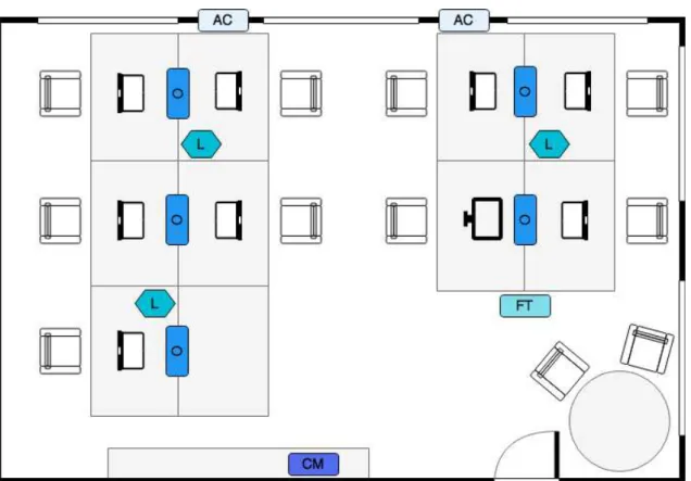
Figure 3.1: SmartLab simplified 2D model. Legend: AC - Air Conditioning, CM - Coffee Machine, FT - Fish Tank, L - Light Bulb, O - Outlet
3.2 Physical Setup
As mentioned before, the SmartLab is equipped with several components. These components can be distributed by different categories (represented in Table3.1). In the sensors category, we include all the devices responsible for acquiring values about the SmartLab environment. Currently, we measure light intensity, temperature, both inside and outside the room, and energy consumption. It is also implemented a system for occupancy detection (described in section 3.4). The actuators category is composed of the devices responsible to change a specific physical value and control the energy waste in every desk present in the room. The computer will be used as a control component, responsible to evaluate the device’s data and apply the required logic to understand what commands need to be sent to the actuators.
3 . 2 . P H YS I CA L S E T U P
Table 3.1: SmartLab physical components installed
Component Type Description
LED Lights Actuator Used to change the light intensity of the room. It can be turned on or off. It is also possible to set a specific value for light intensity and colour.
Outlets Sensor/Actuator Outlets have both measuring and sensing ca-pabilities. They can be used to measure the energy at a specific workstation. On the other hand, it is possible to turn on or offthe outlet. Estimote Beacons Sensor Estimote Beacons are used for occupancy
detec-tion, temperature and light measuring.
Computer Controller The computer used as the main controller of the installed devices in the room.
Table 3.2: Fish tank equipped components
Component Type Description
Open Aquarium Controller Responsible for automating the control and main-tenance tasks that take place in the fish tank, in order to maintain a good, environment to the fish. Ph level sensor Sensor Component used to measure the Ph level of the
tank water.
Temperature sensor Sensor Component used to measure the current tempera-ture of the water.
Water level sensor Sensor Component used to measure the level of the water inside the tank that may decrease due to evapora-tion.
Lights Actuator The tank has some plants that need a certain time of light exposure. This actuator is responsible to provide luminosity to the plants inside the tank if the natural light is not sufficient.
Ventilator Actuator Based on the water temperature, this actuator is used to cool down the water if high-temperature levels are measured.
Feeder Actuator This actuator is used to feed the fish according to a pre-defined schedule or, through the computer.
3.3 Available Services
The distributed components mentioned before provide a set of services. The following sections describe in more detail the services supported by the current setup present in the SmartLab.
3.3.1 Control and Monitor
The SmartLab has a computer responsible for control and monitor activities. It pro-vides the capability to get information about the state of the sensors and control actuators through an implementedApplication Program Interface (API). AUser Interface (UI)is also provided in order to visualise pertinent information about the components installed in the room.
All the components listed before are based on Internet communication. Therefore, all the components have a unique address so that the computer can communicate through the component IP address.
3.3.2 Lights
It is possible to observe in Figure3.1that there are some light bulbs installed in the SmartLab. These bulbs can be switched on/offdirectly in the bulb switch as a normal one, or remotely through the light bulbsAPI. The computer provides the mechanisms to obtain the status of each bulb in the room, to switch it on or off, and to change the light intensity and colour.
3.4 Occupants Comfort
The SmartLab is used as a workroom and occasionally for meetings. Thus, it is at-tended by different types of people. To provide comfort to the occupants while reducing energy costs, it is required to implement mechanisms so that the system has knowledge about the presence of occupants in the room.
To accomplish this requirement the SmartLab is equipped with a set of devices (Bea-cons) to detect human presence through proximity technologies. Beacons are tiny, low power computers that can be attached to walls or objects in the physical world. These devices can help to provide the knowledge about human or specific entities present in the SmartLab.
3 . 5 . S U M M A RY
The data provided by the occupancy detection mechanisms allow us to adopt strate-gies based on the presence of occupants, such as switching offthe lights or the unused outlets when no one is present in the room. Thus, it is possible to reduce energy costs based on the occupancy data.
3.5 Summary
C
h
a
p
t
e
r
4
Stat e o f t h e a rt o f Io T p l at f o r m s
This Chapter presents the state of the art of theIoTarchitectures (section4.1) and the required elements to accomplish an IoTsolution (section 4.2). Then, it introduces some existing platforms for implementing anIoTsolution (section4.3). Then, it presents a list of the key concepts and features an IoT solution should provide (section4.4), and whether these platforms provide or not these concepts. After explaining what anIoTplatform is, it introduces theIoTmiddleware concept (section4.5) and Fog Computing (section4.6), and explains how these concepts are related to the IoTarchitecture and platforms. It ends by presenting howIoT
enhancesBAS(section4.7).
4.1 Internet of Things Architectures
AnIoTarchitecture should have the capacity to interconnect many heterogeneous de-vices, collect data from multiple sources, and connect several services in order to provide the expected functionality. Before discussing how an IoTarchitecture is structured, it is important to mention the requirements these architectures should take into account. Wang et al. [Wan+17] and Ray [Ray16] list these considerations when designing anIoT architecture:
• Interoperability: Allows the integration of heterogeneous devices, networks, sys-tems and services across domains and syssys-tems.
• Service Oriented Architecture principle: Allows third-parties to offer and con-sume services.
• Service modularisation and loose coupling: Simplifies provided and consumed services by third-parties through reusable and modularized services.
• Multipoint communication: Adopts mechanisms to allow objects to communicate with multiple objects at the same time.
• Dynamic and runtime reconfiguration: Enables adding and removing objects dy-namically to networks. Due to network topology changes, it should allocate re-sources dynamically in order to create flows among all objects.
• Simplified deployment: Simplify the deployment ofIoTin order to reduce devel-opment costs.
• Controlled interaction and decentralisation: Supports distributed data accessing, processing and storage. It allows the users to decide which data can be shared.
Now we can describe howIoTarchitectures are usually organised. There are several approaches that try to organise the architecture in several layers but the most common are the 3 and 5 layer architecture [AF+15]. The 5 layer architecture (illustrated in Figure4.1) is composed of the following layers [AF+15;Ara+16;Li+15;Mar+17;Thi15]:
• Perception Layer: Composed of all the devices that interact with the physical world in order to collect data (sensors) or to change a desired state or value (actuators). Every device in this layer has a unique identifier (name or address) that identifies it in the digital domain.
4 . 2 . I N T E R N E T O F T H I N G S E L E M E N T S
• Middleware Layer: This layer pairs a service with its requester based on unique address or names. It provides an abstraction mechanism that enables developers to work with models that represent a specific object without worrying about hardware specifications. This layer is also responsible for making decisions based on the received data and store data in databases.
• Application Layer: Provides output information based on the services requested by the end users. It shapes the application to a specific context such as smart home, smart city and many others.
• Business Layer: Responsible for system configuration and monitoring activities. Represents the tools used to build reports and graphs based on the data received from the application layer. This layer also represents the mechanisms used to predict system behaviour based on big data analysis.
Figure 4.1: Internet of Things 5 Layer Architecture (adapted from [Kha+12])
The 3 layer architecture is an abstraction of the 5 layer architecture. Being struc-tured as Perception Layer, Network Layer and Application Layer. The last layer (Ap-plication Layer) represents a merge between the Middleware, Ap(Ap-plication and Business Layers [AF+15].
4.2 Internet of Things Elements
There are a set of main elements needed to deliver the expected functionality from IoTbased on the architecture layers mentioned before. These elements can be divided into the following categories [AF+15;Mar+17;Min13;Pra+16;Wan+16]:
• Sensing: Sensing refers to the capacity to collect data from the environment through the related objects, analyse, and take specific actions based on the collected data. TheIoTsensing devices can be smart sensors, actuators and wearable sensors.
• Communication: Communication is a crucial part of theIoT. It can be restricted to the characteristics of the devices such as battery life, data transmission limited range and protocols. The most common protocols used are Wi-Fi, ZigBee, GSM, Bluetooth, Z-Wave, 6LowPAN, Message Queuing Telemetry Transport (MQTT), Thread and many others. Proximity communications such RFID,Near Field Communication
(NFC)andBLE(Beacons) are commonly used.
• Computation: Computation is composed of hardware platforms such as Arduino, Raspberry Pi and others. Cloud platforms can also be used to provide storing or processing functionalities.
• Services: IoTservices can be categorised into four types responsible for the follow-ing tasks:
– Identity-related Service: Map the identified real-world objects to virtual ob-jects;
– Information Aggregation Service: Collect and summarise the data provided by the devices;
– Collaborative-Aware Service: Make decisions based on the data provided by the Information Aggregation services;
– Ubiquitous Service: Provide Collaborative-Aware services to anyone at any-time.
• Semantics: The ability to extract knowledge to provide the required services refers to Semantic. In order to extract knowledge, it is required to model information, recognize and analyse data to make sense.
4.3 Internet of Things Platforms
AnIoTplatform provides a set of generic functionalities that can be used to build anIoTapplication. It is a virtual solution, where data drives business intelligence and each device has something to talk with another device. Meaning that anIoTplatform translates devices data so that it can be used intelligently by other devices. Additionally, anIoTplatform provides the required tools that enable a user to implement business use cases and it provides data management and real-time analysis [NC15].
4 . 3 . I N T E R N E T O F T H I N G S P L AT F O R M S
criteria that they provide documentation explaining the architecture on which they are based. The following sections briefly describe the selectedIoTplatforms.
4.3.1 WSO2 IoT
WSO2 is an open-source technology company founded by Dr Sanjiva Weerawarana and Paul Fremantle in August 2005. The platform created by this company is based on theOpen Service Gateway Initiative (OSGi)technology which allows components to be dynamically installed, started, stopped, updated, and removed. Therefore, it is possible to achieve a completely modular solution [Fre16a;Inc16a;Inccea]. In order to fulfil the IoTparadigm, the WSO2 IoT Server was built by reusing the WSO2 components based on a reference architecture.
The architecture, represented in Figure 4.2, is organised in five horizontal layers and two vertical layers. These vertical layers (also called cross-cutting layers) represent the functionality that spans layers. This means these vertical layers represent a set of functionalities (caching, validation, authentication) that are accessible to all the layers. Each layer is composed of multiple components that provide essential capabilities that help to implement a scalableIoTplatform. These capabilities include tools to connect and manage all the devices, data analytics,APImanagement for devices and web-based UIs.
Figure 4.2: WSO2 architecture (adapted from [Fre16a])
4.3.2 IBM Watson IoT
IBM Watson IoT is a cloud platform created by IBM in 2014. This platform helps to create anIoTsolution that aggregate data collected by the connected devices, sensors, and gateways. This platform was built based on an architecture, represented in Figure 4.3, structured in five layers.
Figure 4.3: IBM Watson IoT architecture (adapted from [Watd])
Comparing the IBM Watson IoT architecture to the five layers architecture mentioned before, the User layers represents the Application layer. The Proximity network corre-sponds to the Perception layer. The Public network represents the Network layer. The Provider Cloud layer represents the Middleware layer. Finally, the Enterprise Network corresponds to the Business layer.
To fulfil theIoTparadigm IBM Watson IoT uses multiple platform services, each one responsible for a set of specific tasks. These services provide the tools to create an IoT solution. IBM Watson IoT provides recipes to simplify the connection of devices and scenarios that help to implement the architecture [Watb;Watd].
4.3.3 ThingSpeak IoT
ThingSpeak is cross-platform created in 2010, that enables the creation of sensor applications. This platform was built based on an architecture, represented in Figure4.4, structured in three layers.
Comparing the ThingSpeak IoT architecture to the three layers architecture men-tioned before, the Things layer represents the Perception layer. The Cloud Service cor-responds to the Middleware layer and the Services and Application layer represents the Application layer.
4 . 3 . I N T E R N E T O F T H I N G S P L AT F O R M S
Figure 4.4: ThingSpeak IoT architecture (adapted from [Thi14])
4.3.4 Microsoft Azure IoT
Azure IoT Suite is an enterprise-grade solution created by Microsoft in 2016. This platform helps to build, deploy, and manageIoTsolutions using Azure services based on an architecture. The architecture, represented in Figure4.5, is structured in three layers and provides the required components to enable the communication between devices and cloud-based systems, and the integration of analytics, control and business processes.
Figure 4.5: Azure architecture (adapted from [Fre16b])
Comparing the Azure IoT architecture to the three layers architecture mentioned before, the Device connectivity layer represents the Perception layer. The Data processing, Analytics and Management correspond to the Middleware layer. Lastly, the Presentation and Business represent the Application layer.
Azure IoT Suite provides preconfigured, completed and working solutions to address commonIoTscenarios. The Azure IoT Suite is composed of several core platform services and application level components. The components provide a set of required functionali-ties in order the achieve a modular and flexibleIoTsolution [DBce;Fre16b].
4.3.5 Amazon Web Service
Amazon WS is anInfrastructure as a Service (IaaS)platform created by Amazon in 2006. This platform allows to easily connect devices, and interact with cloud services. This platform is based on a three layers architecture, represented in Figure 4.6, that provide the capabilities of device management, data analytics and presentation, and external communication to other services.
Figure 4.6: Amazon WS architecture (adapted from [Awsb])
represents the Middleware layer and the Services and Applications correspond to the Application layer.
In Amazon WS the Things layer represents the provided SDKs that help to connect the hardware devices, authenticate and exchange messages using different communication protocols. This platform also provides a concept of Device Shadow of each device that includes the device latest state, making it easier to build applications that interact with the connected devices [Awsa;Awsb].
4.4 Comparison of Internet of Things Platforms
Once the platforms have been described, we can start to define the most relevant aspects to be compared. These aspects are structured in four categories. In section4.4.1 we list the key concepts anIoTplatform should provide. In section 4.4.2we detail the most common mechanisms used for data analytics. In section 4.4.3 we describe the communication models found in these platforms. Lastly, section 4.4.4presents all the features provided by the selectedIoTplatforms.
4.4.1 Key concepts
After analysing in more detail the existing solutions, we noticed the concepts that an IoT platform should provide. The following list describes the key concepts from the analysis conducted and Table4.1compares these concepts between the mentioned platforms.
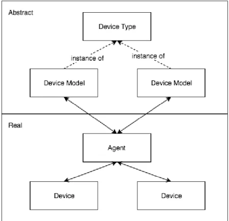
• Device Model: Enables the representation of device details, such as model and serial number, data emitted, configuration parameters and its operations.
• Device Management: Capability to support device management in order to main-tain a list of connected devices and their status. It should provide tools to help in device registry, integration, enable/disable device features, control device identi-fiers and localisation, and allow error reporting and handling.
4 . 4 . COM PA R I S O N O F I N T E R N E T O F T H I N G S P L AT F O R M S
• Analytics: Provide tools to collect data from multiple sources and integrate real-time, predictive and interactive analysis.
• Visualisation: Provides web-basedUIsor dashboards for data visualisation.
• External Communication: Allows the interaction with systems outside its network using machine-to-machine communication (APIs).
• Identity and Access Management: Ensures security while connecting multiple identities from different applications,APIsand devices regardless of the standards which they adopt.
Table 4.1: Comparison of the key concepts of the studied platforms. Legend: no mention, low or no support#, medium or partial supportG#, high or full support
WSO2 IBM Azure AWS ThingSpeak
Device model #
Device management #
Integration Analytics Visualisation
External communication
Identity and Access Management
4.4.2 Data analytics
As mentioned in section4.2anIoTsolution should provide the capability to extract knowledge from the data collected. In order to extract valuable information, several mechanisms can be used.
Note that in section4.4.1, we list Analytics as a key concept. We consider important to specify this aspect because, in our case study multiple mechanisms for data analytics can be used, in order to provide a better comfort for the occupants and to realise strategies for reducing energy consumption costs.
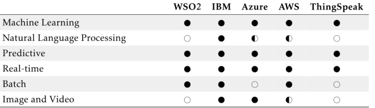
The following list describes the mechanisms found in the analysis of solutions and Table4.2compares these concepts between the mentioned platforms.
• Machine Learning: Capability to learn and make predictions based on data through learning algorithms;
• Natural Language Processing: Ability to analyse, understand, and derive meaning from human writing or speech;
• Real-time: Ability to analyse the data as soon as it enters the system;
• Batch: Ability to process transactions in a group without requiring user interaction;
• Image and Video: Extract meaningful information from images and videos.
Table 4.2: Comparison of the data analytics tools provided by the studied platforms. Legend: no mention, low or no support#, medium or partial supportG#, high or full support
WSO2 IBM Azure AWS ThingSpeak Machine Learning
Natural Language Processing # G# G# #
Predictive Real-time
Batch # #
Image and Video # G# #
4.4.3 Communication models
IoTis about to connect everything, and therefore it is possible to find many types of communications between the existing components. On that matter, a wide range of protocols arises in order to support the different communication models. The following sections describe the communication models found inIoT[Iot;MP]. Although in different ways, all the platforms provide the mechanisms to accomplish these communication models. The biggest difference between them resides in the way they simplify these communications, whether through services or custom gateways.
Device-to-Device Communication
Represents the communication between two or more devices that exchange data be-tween them, as the example in Figure4.7. These devices can communicate through many types of networks, including IP networks, but most often use protocols such as Bluetooth, Z-Wave, ZigBee and others. This communication model transfers small data packages of information between devices at a relatively low data rate [HAM16;MP].
4 . 4 . COM PA R I S O N O F I N T E R N E T O F T H I N G S P L AT F O R M S
Device-to-Cloud Communication
In the Device-to-cloud communication, exemplified in Figure4.7, the device is con-nected directly to an Internet cloud service to exchange data. This approach uses com-munication mechanisms like traditional wired Ethernet or Wi-Fi connections to estab-lish a connection between the device and the network, but can also use cellular tech-nology. Device-to-cloud communication provides the capability to access devices re-motely [HAM16;MP].
Figure 4.8: Device-to-Cloud communication model example (adapted from [HAM16])
Device-to-Gateway Communication
Device-to-gateway communication, exemplified in Figure4.9, represents the commu-nication between the device through aGatewayin order to reach an Internet cloud service. Gateway devices serve as an intermediary between the device and the cloud service and provide other functionalities such as security and data protocol translation. Gateway de-vices can fill the gap between dede-vices with different communications protocols [HAM16; MP].
Back-end data sharing
Back-end data sharing, exemplified in Figure4.10 is a communication model that enables the end users to export and analyse data from an Internet cloud service in combi-nation with data from other sources. This model also provides authorised third parties to access devices data [HAM16;MP].
Figure 4.10: Back-end data sharing communication model example (adapted from [HAM16])
4.4.4 Features
The following list describes the features found in the platforms analysis and Table4.3 compares these concepts between the mentioned platforms.
• Libraries/SDK: Provide code to simplify the building and connection of devices and applications that are used by theIoTplatform;
• Virtual/Shadow Device: Used as a communication layer between the application and the device. The virtual/shadow act as a persistent, virtual representation of the device state in a specific time;
• Agents: Software installed on the devices used to perform actions on behalf of another component;
• Rule Engine: Ability to create rules in order to trigger a specific action upon an event occurrence;
• Group/Zone: Ability to create groups or zones and manage the belonging devices;
• Tasking: Ability to forward control commands to the devices;
• Messaging Services: Ability to publish or subscribe to topics of the devices;
4 . 4 . COM PA R I S O N O F I N T E R N E T O F T H I N G S P L AT F O R M S
Table 4.3: Comparison of features provided by the studied platforms. Legend: no men-tion, low or no support#, medium or partial supportG#, high or full support
WSO2 IBM Azure AWS ThingSpeak
Libraries/SDK #
Virtual/Shadow Device #
Agents #
Rule Engine
Group/Zone G# #
Tasking
Messaging Services G#
Alerts and Notifications
4.4.5 Discussion
Architectures are either more or less suitable for a specific context. Therefore, there is no such thing as an inherently good or bad architecture. However, there are some guidelines that should be followed when designing architectures. Even if the architec-ture does not satisfy one of the rules, it does not imply that the architecarchitec-ture will fail its purpose [Bas+12;Som10].
As mentioned in section 4.1, the IoTarchitectures are usually structured in 3 or 5 layers, and all the platforms described in section4.3are in accordance with these patterns.
It is important to note that there are many solutions that allow us to create anIoT solution. The platforms mentioned in section 4.3 were selected because they are the ones that provide documentation explaining the architecture on which they are based and their architectures and elements provided resemble on the IoT architecture and elements mentioned in sections4.1and4.2. Moreover, the features they offer are the ones that fit the case study. However, there are other solutions available that should not be discarded. We do not consider these solutions in this thesis because they do not provide documentation explaining the architecture they are based or they do not provide the functionalities.
A question to be taken into account is the fact that some of the solutions mentioned are Platform as a Service (PaaS). This means that these platforms allow the users to develop, run, and manage applications without the concern of building and maintaining the infrastructure required to develop and launch an application [Law08]. This type of platforms have some advantages such as [Law08]:
• Productivity/Efficiency: Hosting the development environment increases produc-tivity and lets release products faster and reduce software costs;
However,PaaSplatforms have some drawbacks too [Law08]:
• Accessibility: Connectivity problems or thePaaSsystem crash and the platform vendor goes out of business making the platform inaccessible;
• Portability: When using these platforms the users are dependent on the platform which they are working with. The developed applications are limited to the plat-form used and in many cases, there is no easy way to transfer the product elsewhere;
• Security: All content is on the side of the platform vendor. The users are not in control of sensitive information within the platform.
In our evaluation, we will take into consideration the characteristics usually associ-ated with PaaS platforms we just introduced. However, we will simply assume these characteristics are present/absence if the platform under evaluation is aPaaSor not. That is, we will not further investigate the degree of each characteristic in the corresponding platform.
Another issue to be taken into consideration is the fact that solutions are composed of several components. Most of the components already exist. Therefore, by aggregating these components and providing the mechanisms to make them communicate with each other, it is possible to achieve a solution that fits theIoTrequirements and functionalities.
However, we emphasise that, although the platforms can provide the expected char-acteristics from anIoTsolution, the biggest difference that can arise between them is in terms of performance, usability, scalability, and ease of setup.
4.5 Internet of Things Middleware
In the previous sections, we saw what is anIoTplatform, its requirements and pre-sented multiple architecture approaches. However, there are still solutions that abstract one of the problems of theIoTplatforms. As mentioned before, nowadays there are mul-tiple communication protocols and many types of devices. This often makes it harder to handle the communication between all devices. Therefore, other solutions may arise in order to provide smooth communication between all the components of anIoTsystem.
4 . 6 . F O G COM P U T I N G
There are severalIoTmiddleware approaches, and these also have different types of architectures. These architectures can be classified as service-based, cloud-based and actor-based.
The service-basedIoTfollows a three-layer architecture composed of Physical Plane (sensors, actuators), Virtual Plane (server infrastructure) and the Application Plane (util-ity). This approach has some limitations, namely because it provides the functionalities to collect data but not for data analysis. It is also a heavy solution that requires com-putational resources and needs to be deployed in multiple nodes or powerful gateways between theIoTdevices.
The cloud-basedIoTis composed of functional blocks and the services are limited to the existing blocks. The provided functionalities are exposed through a set ofAPIs. The resources provided can be accessed and controlled only by vendors provided applications or cloud supportedAPIs.
The actor-basedIoTcan be visualised as a three circular architecture. The outermost circle represents the sensors and actuators, the middle circle represents the devices used for access and the inner circle represents the cloud. A particularity of this approach is that the middleware can be embedded in all the layers, since it is designed to be light-weight. Thus, the middleware computation units are distributed across the network.
The difference between these approaches resides on the provided support to add new devices, the type of services and computer units they support and where the middleware can be deployed. The service-based is deployed on servers or in the cloud. Usually, it has a limited set of functionalities and it is restricted to external services integration. The service-based is also not designed to be extendible or customised by the users. The actor-based architecture provides the best latency and scalability because it can be deployed in any layer and device. Thus, it can perform computations where it provides more benefits.
All these approaches support security and privacy. However, the cloud and service-based approaches may have weak security in the communication between the middle-ware and the physical devices, due to the fact that middlemiddle-ware cannot be deployed or embedded on devices. Therefore, it can compromise the data sent from devices to the middleware [Ngu+17].
4.6 Fog Computing
infeasible in many scenarios [Yan+14]. Yannuzzi et al. enumerates the following scenarios that are not favoured by the current cloud [Yan+14]:
• Mobility: Applications that require computing and storage support on the move. Such support can be required under fast mobility patterns. Traditional cloud needs to adopt strategies to achieve pervasiveness while providing the reliability expected by these applications.
• Reliable control and real-time: Applications placed in locations where the com-munication with the cloud is to expensive or unreliable. Obviously, we cannot guarantee reliable control under such conditions when these applications require very low latency. In these applications ofIoT, sometimes are required computing resources to control and apply logic. Therefore, these scenarios demand external computing and storage resources. However, current communications and cloud are not prepared to handle these applications requirements based on low latency, or real-time.
• Data aggregation and analytics: Applications that involve data management and processing are well supported by the traditional cloud centralised model, and it is perfectly suitable for controlling and managing data produced by a large number of components. However, when multiple distributed components produce data and demand analytics and external processing for decision making, the traditional cloud may not have the capability to ensure this. Instead, these applications require resources placed close to the data producers that can be used for local processing and data analytics for fast decision making. Relevant data will be pushed to the cloud only when its content is important.
Note that these scenarios are listed as features or requirements of anIoTplatform, and yet there areIoTplatforms based on cloud computing or in centralised data management mechanisms. So, we can conclude that the IoT platforms face complex challenges for supporting the requirements presented. Thus, the concept of Fog Computing offers a way to deal with these challenges. Yannuzzi et al. shows why combining the Fog Computing with cloud computing is the most plausible way to build an adaptable and scalable platform forIoT.
The concept of Fog Computing consists of carrying out computation and storage functionalities to the near edges of the network. Figure4.11represents the main vision of Fog Computing. Note that there is a layer between the physical devices and the upper layer. The Fog level is composed of multiple nodes responsible for some computing and storage functionalities in order to handle the dependency that the bottom layer has with the upper layer [Chi16].
![Figure 2.1: Cyber-Physical System model (adapted from [LS15])](https://thumb-eu.123doks.com/thumbv2/123dok_br/16525289.735970/32.892.256.638.404.665/figure-cyber-physical-system-model-adapted-from-ls.webp)