Sequence networks to the calculation of two-simultaneous faults
at the same location
Ailson P. Moura
a,b,⇑, J.A. Peças Lopes
c, Adriano A.F. de Moura
d aDepartment of Electrical Engineering, Federal University of Ceara, Pici Campus, BrazilbCAPES Foundation, Brazil
cFaculty of Electrical and Computer Engineering, University of Porto, Instituto de Engenharia de Sistemas e Computadores do Porto (INESCPorto), 4200-465 Porto, Portugal dDepartment of Environmental Science and Technology, Federal Rural University of Semi-Arid, Av. Francisco Mota, 572 Bairro Costa e Silva, Mossoró, RN CEP: 59.625-900, Brazil
a r t i c l e
i n f o
Article history:
Received 6 December 2013
Received in revised form 21 January 2015 Accepted 31 January 2015
Available online 18 February 2015
Keywords: Fault Power system Sequence networks Symmetrical components
a b s t r a c t
The system of symmetrical components (012-system) can be used to simulate symmetrical and asym-metrical operation of power systems. However, the classical literature of Power Systems Analysis does not present one equivalent circuit in 012-system to two-simultaneous faults where there are a single-line-to-ground fault and a bolted line-to-line fault. This paper presents the equations and the new equiv-alent circuit mentioned. In addition, we present a comparison of results between the proposed approach and the output of the commercial software ANAFAS, which validates the methodology. We find evidence that the new equivalent circuit developed can substitute the equivalent circuits used to calculate a single line-to-ground fault and a bolted line-to-line fault.
Ó2015 Elsevier Ltd. All rights reserved.
Introduction
The system of symmetrical components can be used for the analysis of symmetrical and asymmetrical operation of power sys-tems. Faults in general and in particular short-circuit currents are the most severe operating conditions in power systems. Hence, each of the different faults, e.g., single-phase-to-ground, three-phase, etc., can be represented by an equivalent circuit diagram in the ABC-system (system of phase components) and by this in the 012-system (system of symmetrical components) as well.
One of the most difficult problems in the solution of faulted net-works is that involving two or more faults which occur simulta-neously[1].
On the other hand, the need to improve service availability has increased the complexity of distribution network topology. Discon-nected switches allow transferring loads to alternate sources under emergency conditions. Limitations on the rights of way make it necessary to use multicircuit overhead lines or single-circuit lines that run close to each other. As a result, simultaneous faults involv-ing more than one circuit are becominvolv-ing quite common. Typical causes which forces more than one fault at a single location include [2]:
Multicircuit lines or lines sharing the same right of way.
Switching operations.
A stroke of lightning (thunderstorms).
A man-caused accident.
The classical books of Power Systems Analysis[1,3,4]present the following equivalent circuits for two-simultaneous faults at the same location: Bolted three-phase (two-simultaneous bolted to-line fault), three-phase to ground (two-simultaneous line-to-line-to-ground fault) and line-line-to-line-to-ground (two-simulta-neous line-to-ground fault). However, one common drawback of the Power Systems Analysis literature[1,3–5]is not presenting a procedure to derive an equivalent circuit to handle two-simulta-neous faults of the type: single-line-to-ground fault and a bolted line-to-line fault (SLG-BLL-F). Furthermore, several other past and recent publications do not fill this gap as the references[6–15].
In Power Engineering, the specific topic about fault analysis receives much attention, as it is deeply important for the electric power industry. This importance is justified by the fact that fault analysis precedes power system protection studies. Take for exam-ple: when simultaneous faults occur on the transmission line, they have an effect on the operation of distance relays installed in the system. During faults, it is mandatory for the protection system to operate precisely. Therefore, if the simultaneous faults could be analyzed, it would be very useful[16]. Thus, it is important that also simultaneous SLG-BLL-F is studied.
http://dx.doi.org/10.1016/j.ijepes.2015.01.037 0142-0615/Ó2015 Elsevier Ltd. All rights reserved.
⇑Corresponding author at: Department of Electrical Engineering, Federal Uni-versity of Ceara, Pici Campus, Brazil.
E-mail addresses: [email protected] (A.P. Moura), [email protected] (J.A.P. Lopes), [email protected](A.A.F. de Moura).
Contents lists available atScienceDirect
Electrical Power and Energy Systems
This paper provides the equations and a new equivalent circuit in the 012-system to a simultaneous SLG-BLL-F at the same loca-tion of the three-phase power system.
The paper is organized as follows: Firstly, a complete demon-stration of the proposed equivalent circuit is presented. Secondly the equivalent circuit is validated. Numerical examples show step-by-step how to calculate a simultaneous SLG-BLL-F. Final con-clusions and references are contained in this paper as well.
Equivalent circuit diagram in the 012-system
Whichever fault in the three-phase a.c. system has to be described by three independent conditions for the voltages, currents or combinations of both. Since any of the three phases can be arbitrarily labeled phase a, we do not consider single line-to-ground faults on other phases. The fault equations in the ABC-system are presented in the case of two-simultaneous faults where there are simultaneous SLG-BLL-F as follows.
Va¼zfIa; Ib¼ Ic; Vb¼Vc ð1Þ
where single-line-to-grounded fault impedance (SLGI) iszf.
The transformation into the system of symmetrical components is carried out using the transformation matrices by Eqs.(2) and (3).
Va Vb Vc 2 6 4 3 7 5¼
1 1 1
1 ~a2 ~a
1 ~a ~a2 2 6 4 3 7 5
Va0 Va1 Va2 2
6 4
3
7
5 ð2Þ
Va0 Va1 Va2 2 6 4 3 7 5¼ 1 3
1 1 1
1 ~a ~a2
1 ~a2 ~a 2 6 4 3 7 5 Va Vb Vc 2 6 4 3 7
5 ð3Þ
where~a¼1<120
The fault equations for the currents in the system of symmetri-cal components are
Ia0
Ia1
Ia2 2 6 4 3 7 5¼ 1 3
1 1 1
1 ~a ~a2
1 ~a2 ~a 2 6 4 3 7 5 Ia Ic Ic 2 6 4 3 7
5 ð4aÞ
Therefore,
Ia¼3Ia0 ð4bÞ
Ia1¼ Ia2þ2Ia0 ð4cÞ
and for the voltages
Va0
Va1
Va2 2 6 4 3 7 5¼ 1 3
1 1 1
1 ~a ~a2
1 ~a2 ~a 2 6 4 3 7 5 Va Vb Vb 2 6 4 3 7
5 ð4dÞ
Therefore,
Va1¼Va2 ð4eÞ
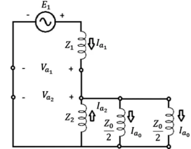
The fault conditions as per Eqs.4(a)–(4e)can only be realized by a series–parallel connection of the positive-, negative- and zero-sequence component. The equivalent circuit diagram in the system of symmetrical components is outlined inFig. 1. The posi-tive-, negative- and zero-sequence component are represented by impedancesZ1;Z2andZ0, withZ0¼z0þ3zf. Wherez0is the zero sequence impedance network.
The currents and voltages of the system of symmetrical compo-nents are then calculated as
Ia1¼
E1ð4Z2þZ0Þ
D ; Ia2¼
E1Z0
D ; Ia0¼
2E1Z2
D ð5aÞ
Va1¼E1Z1Ia1; Va2¼ Z2Ia2; Va0¼ 2Va1þ3zfIa0 ð5bÞ
where
D¼Z2Z0þZ1ð4Z2þZ0Þ
Validating the circuit developed
Fault currents calculation is a key factor in determining the tap settings of protection relays for many practical applications.
The commercial software Simultaneous Fault Analysis (ANA-FAS), developed by the Electric Energy Researches Center (CEPEL) – Brazil, was used just for verification of the fault currents and voltages calculation.
Consider the modified Example 3.1 of the reference[1]. The Thevenin voltage at bus C is E1¼1:0 (pu). The simple power system shown inFig. 2, consists of a generator, transformer, trans-mission line, load transformer, and load. Consider simultaneous SLG-BLL-F at bus C with a SLGI of 4 ohms.
The following data concerning the system is known: Generator: 25 MVA, 10 kV,x= 0.125 pu, connected Y-grounded. T1: 30 MVA, 10–20 kV, x= 0.105, connected D—Y-grounded. Line: Z= 2 + j4 ohm. T2: 20 MVA, 5–20 kV,x= 0.05, connectedY—D. Load: static (constantz) load of 10 + j5 MVA at 5 kV.
Solution
According to reference[1], the impedances (pu) calculated are:
Z1¼0:1287þ0:3059j; Z2¼Z1; zf ¼0:2; Zo¼0:1þ0:27jþ 3zf¼ 0:7þ0:27j.
Now, we may synthesize phase currents and phase voltages both in pu. We calculate the phase currents and the phase voltages to the equivalent circuit using Eqs.(5a), (5b) and (2).
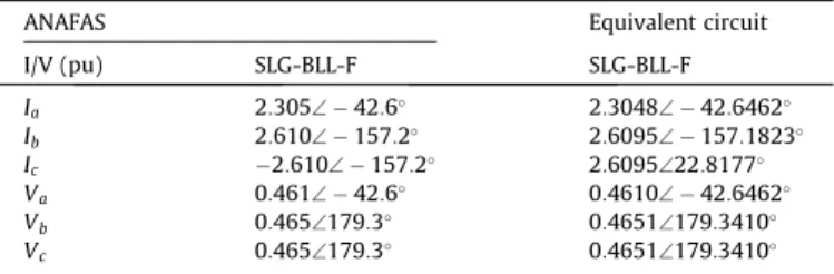
Table 1shows the results obtained to simultaneous SLG-BLL-F at bus C.
The results from equivalent circuit and the results from ANAFAS can be seen to be much closer. Therefore, the equivalent circuit proposed can be considered as validated.
Fig. 1.Equivalent circuit diagram in the 012-system to simultaneous SLG-BLL-F.
Procedure to the calculation of two-simultaneous fault
In this particular item, we will give two numerical examples to illustrate the calculation of simultaneous SLG-BLL-F step-by-step. The first example is a small system and the second example is a medium system. Thus, we will take as examples, the modified Example 9.1 of the reference[3]and the IEEE 14-bus test system [17].
In general, the fault analysis is performed from the following path[4]:
1. The power system must be represented by its positive, negative and zero-sequence networks (when faults without earth occur the zero-sequence network is not used, and the negative and zero-sequence networks are removed for the balanced three-phase fault condition). Then, the calculation of impedances in pu for all power systems components is required: lines, trans-formers, generators, cables and other elements of the power system.
2. In this step, each of the sequence networks should be reduced to its simplest form. The three sequence networks equivalent, i.e. positive, negative and zero are represented as series–parallel and a series arrangement of the p.u. impedances. Then, these are substituted by the single equivalent impedance for each sequence network. When this procedure is performed delta-star or star-delta transformations may be necessary.
3. The suitable symmetrical-component equations are used to find the phase-sequence components of the current in fault under the particular short-circuit condition.
4. The p.u. phase-current values at the point of fault are determined.
5. Finally, the actual values of the phase-currents are calculated by multiplying obtained p.u. values by the base current at the point of fault.
The procedure described above provides a complete analysis of the given power system for specified fault condition. This
procedure can be applied for two types of case studies: First case study is using small systems and second case study is using med-ium or large systems. The two case studies are showed as follows:
First case study of fault analysis: small systems
Consider the modified Example 9.1 of the reference[3]. The single-line diagram of a three-phase power system is shown inFig. 3. Equipment ratings are given as follows:
Synchronous generator:
G1 1000 MVA 15 kVX00
d¼X2¼0:18; X0¼0:07 per unit
G2 1000 MVA 15 kVX00
d¼X2¼0:20; X0¼0:10 per unit
G3 500 MVA 13:8 kVX00
d¼X2¼0:15; X0¼0:05 per unit
G4 750 MVA 13:8 kVX00
d¼X2¼0:40; X0¼0:10 per unit
Transformers:
T1 1000 MVA 15 kV
D
=765 kVY X¼0:10 per unitT2 1000 MVA 15 kV
D
=765 kVY X¼0:10 per unitT3 1000 MVA 15 kV
D
=765 kVY X¼0:12 per unitT4 1000 MVA 15 kV
D
=765 kVY X¼0:11 per unitTransmission Lines:
1—2 765 kVX1¼50
X
; X0¼150X
1—3 765 kVX1¼40
X
; X0¼100X
2—3 765 kVX1¼40
X
; X0¼100X
The inductor connected to Generator 3 neutral has a reactance of 0.05 per unit using generator 3 ratings as a base. Calculate simultaneous SLG-BLL-F at bus 1 with a SLGI of zero ohms. Prefault load currents andD—Ytransformer phase shifts are neglected. Pre-fault voltage is 1.0 per unit.
Solution
First step: The first step is to choose apparent power base. The power base can be adopted equal to the power rating of any power system transformer or generator, or may be chosen as a whole number as 1000 or 100 MVA. Here, apparent power base is chosen as a 1000-MVA base in the zone of line 1–2.
Second step: The second step is to choose voltage base. The choice of the voltage base is determined by the voltage rating of
Fig. 3.Power system for numerical example. Table 1
Two-simultaneous fault results.
ANAFAS Equivalent circuit
I/V (pu) SLG-BLL-F SLG-BLL-F
the bus where the fault is located. Here, voltage base is chosen as 765 kV.
Third step: In this step the current base is calculated.
Ibase¼ Sbase ffiffiffi 3
p Vbase
¼ 1000
765 ffiffiffi 3
p ¼0:755 kA
Fourth step: In this step all per unit reactances are calculated. Synchronous generator:
G1X1¼X00d¼X2¼0:18; X0¼0:07 pu
G2X1¼X00d¼X2¼0:20; X0¼0:07 pu
G3X1¼X2¼X00d¼0:15
13:8 15
2 1000
500
¼0:2539 pu
X0¼0:05
13:8 15
2 1000
500
¼0:08464 pu
3Xn¼3X0¼0:2539 pu
G4X1¼X2¼X00d¼0:40
13:8 15
2 1000
750
¼0:4514 pu
X0¼0:10
13:8 15
2 1000
500
¼0:1129 pu
Transformers:
XT1¼0:10 pu
XT2¼0:10 pu
XT3¼0:12
1000 500
¼0:24 pu
XT4¼0:11
1000 750
¼0:1467 pu
Transmission Lines:
ZBASEH¼
765
ð Þ2
1000 ¼585:23
X
Positive/negative sequenceX12¼
50
585:23¼0:08544 pu
X13¼X23¼
40
585:23¼0:06835 pu Zero sequence
X12¼
150
585:23¼0:2563 pu
X13¼X23¼
100
585:23¼0:1709 pu
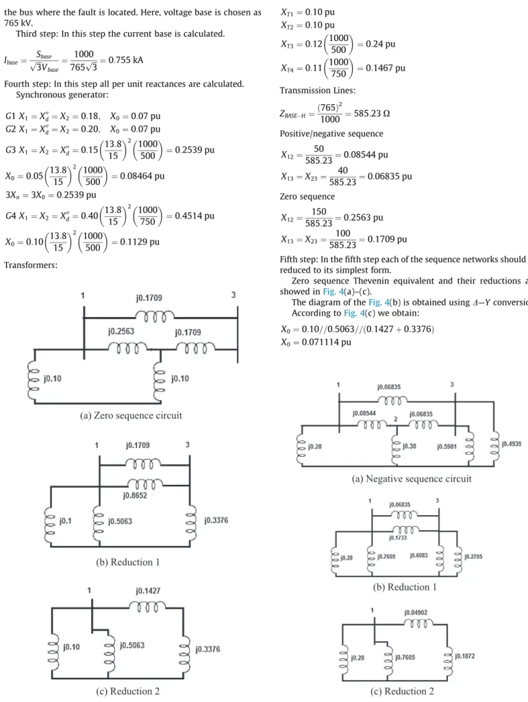
Fifth step: In the fifth step each of the sequence networks should be reduced to its simplest form.
Zero sequence Thevenin equivalent and their reductions are showed inFig. 4(a)–(c).
The diagram of theFig. 4(b) is obtained usingD—Yconversion. According toFig. 4(c) we obtain:
X0¼0:10==0:5063==ð0:1427þ0:3376Þ
X0¼0:071114 pu
(a) Zero sequence circuit
(b) Reduction 1
(c) Reduction 2
Fig. 4.(a–c) Zero sequence circuit and reductions.
(a) Negative sequence circuit
(b) Reduction 1
(c) Reduction 2
where==is a parallel impedance.
Negative sequence Thevenin equivalent and their reductions are showed inFig. 5(a)–(c).
The diagram of theFig. 4(b) is obtained usingY—Dconversion. According toFig. 5(c) we obtain:
X2¼0:28==0:7605==ð0:04902þ0:1872Þ
X2¼0:1097 pu
Similarly,
X1¼0:1097 pu
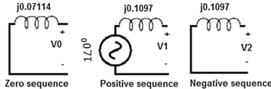
Sixth step: The equivalent positive, negative and zero-sequence networks are represented as an equivalent circuit diagram.
In this step, Thevenin equivalents as viewed from bus 1.Fig. 6 shows these equivalent circuits.
Seventh step: Equivalent circuit diagram in the 012-system to simultaneous SLG-BLL-F.
Fig. 7shows the combination of the equivalent zero, positive and negative sequence networks to calculate simultaneous SLG-BLL-F.
The currents and voltages of the system of symmetrical compo-nents are calculated using Eqs.(5a) and (5b)or using the circuit of theFig. 7.
Ia1¼7:9998\90 pu
Ia2¼1:1160\90 pu
Ia0¼3:4419\90 pu
Va1¼0:1224\180 pu
Va2¼0:1224\0 pu
Va0¼0:2449\0 pu
Eighth step: The p.u. phase-current values at the point of fault are determined.
Using Eq.(2)
Ia Ib Ic 2
6 4
3
7 5¼
1 1 1
1 ~a2 ~a
1 ~a ~a2 2
6 4
3
7 5
3:4419\90
7:9998\90
1:1160\90
2
6 4
3
7 5
Therefore:
Ia¼10:3256\90pu Ib¼7:8945\180pu Ic¼7:8945\0pu
Ninth step: The actual values of the phase-currents are calculated. UsingIbasecalculated in third step
Ia¼7:7958\90kA Ib¼5:9603\180kA Ic¼5:9603\0kA
Now, we can make a comparison with the classical fault situa-tions. The results are shown inTable 2.
One understands then that a simultaneous SLG-BLL-F may have a current value at a phase higher than the current value of the three-phase fault. The results of the simultaneous SLG-BLL-F include the results of LG and LL faults.
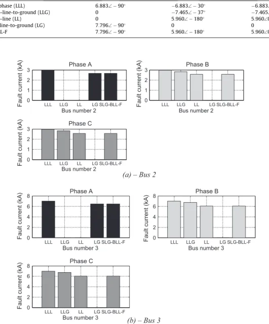
Fig. 8(a) and (b) present the fault currents at buses 2 and 3. It is worth noting that results of the simultaneous SLG-BLL-F also include the results of LG and LL faults.
Then, the equivalent circuit developed can substitute both the equivalent circuits used to calculate a single line-to-ground fault and a bolted line-to-line fault.
Second case study of fault analysis: medium and large systems
The IEEE 14-bus test system[17]was also used for testing the approach described. However, the fault analysis for large systems is done similarly.
The single-line diagram of the IEEE 14-bus is shown inFig. 9. At this time, the procedure of the Fifth step, i.e. (in the fifth step each of the sequence networks should be reduced to its simplest form), is done using classical techniques to form impedance matri-ces. The short-circuit matrix is formed using classical procedure by a step-by-step formation[18]. Other steps are the same as in the case study of the small system.
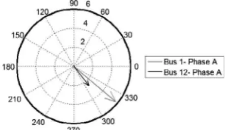
The buses selected for the location of the faults were: 1 and 12, because they present, respectively, the highest and lowest three-phase short-circuit power. The Thevenin equivalent impedances (pu) calculated are: Bus 1, Z1¼0:009118þ0:079893j ; Zo¼ 0:377863þ0:173159j; Bus 12, Z1¼0:129671þ0:299170j; Zo¼0:459552þ0:308492j.
Fig. 6.Equivalent zero, positive and negative sequence networks.
Fig. 10shows the simultaneous SLG-BLL-F currents of the buses 1 and 12 calculated through Eqs.(5a) and (2), and single-line-to-ground fault currents and line-to-line fault currents of the buses 1 and 12 calculated using ANAFAS. The values confirm that the equivalent circuit developed can substitute both the equivalent cir-cuits used to calculate a single line-to-ground fault and a bolted line-to-line fault.
According to the simulation results the advantages and disadvantage of the new equivalent circuit are: (a) Advantages – It can be used for calculating a combination of simultaneous faults in the same location in small and large power systems, and it can substitute equivalent circuits which are used to calculate a single line-to-ground fault and a bolted line-to-line fault; (b) Disadvantage – The impedance between the two phases of the line - line fault is not included in the equivalent circuit.
(a) – Bus 2
(b) – Bus 3
LLL LLG LL LG SLG-BLL-F0 1 2 3
Phase A
Bus number 2
Fault current (kA) 0 LLL LLG LL LG SLG-BLL-F
1 2 3
Phase B
Bus number 2
Fault current (kA)
LLL LLG LL LG SLG-BLL-F
0 1 2 3
Phase C
Bus number 2
Fault current (kA)
LLL LLG LL LG SLG-BLL-F
0 2 4 6
8 Phase A
Bus number 3
Fault current (kA)
LLL LLG LL LG SLG-BLL-F
0 2 4 6
8 Phase B
Bus number 3
Fault current (kA)
LLL LLG LL LG SLG-BLL-F
0 2 4 6
8 Phase C
Bus number 3
Fault current (kA)
Fig. 8.(a, b) Fault currents – buses: 2 and 3. Table 2
Fault current results – bus 1.
Fault Currents (kA)
bus 1 Ia Ib Ic
Three phase (LLL) 6:883\90 6:883\30 6:883\150 Line-to-line-to-ground (LLG) 0 7:465\37 7:465\143
Line-to-line (LL) 0 5:960\180 5:960\0
Single line-to-ground (LG) 7:796\90 0 0
SLG-BLL-F 7:796\90 5:960\180 5:960\0
Conclusion
This paper describes an approach based on symmetrical compo-nents theory to calculate short-circuit currents that result from a simultaneous SLG-BLL-F. Moreover, numerical results were com-pared with results of the commercial software ANAFAS and the new equivalent circuit was validated. The advantages of the new equivalent circuit developed are described as follows. It can substi-tute equivalent circuits which are used to calculate a single line-to-ground fault and a bolted line-to-line fault, and it can be used for calculating a combination of simultaneous faults in the same loca-tion in small and large power systems. In conclusion, we suggest that this new equivalent circuit should be incorporated in short-circuit analysis literature.
References
[1]Anderson Paul M. Analysis of faulted power systems. New York: IEEE Press Power Systems Engineering Series; 1995.
[2]Betanzos Manuel J, Lemus Zavala HE, Alcazar Ramirez E, Escobedo DS, Altuve HJ. Protecting distribution feeders for simultaneous faults. In: 63rd annual conference for protective relay engineers. IEEE conference publications; 2010. p. 1–9.
[3]Duncan Glover J, Sarma Mulukutla S, Overbye Thomas J. Power system analysis & designs. fifth ed. USA: Cengage Learning; 2011.
[4]Grainger JJ, Stevenson Jr WD. Power system analysis. New York: McGraw-Hill, Inc.; 1994.
[5]Blackburn JL. Symmetrical components for power systems engineering. New York: Dekker; 1993.
[6]Wang Yuanyuan, Zeng Xiangjun, Dong Zhaoyang, Huang Yue. Novel protection scheme of stator single-phase-to-ground fault for power transformers. Int J Electr Power Energy Syst 2013;53:321–8.
[7]Rongjie Wang, Yiju Zhan, Haifeng Zhou, Bowen Cui. A fault diagnosis method for three-phase rectifiers. Int J Electr Power Energy Syst 2013;52:266–9. [8]Ou Ting-Chia. Ground fault current analysis with a direct building
algorithm for microgrid distribution. Int J Electr Power Energy Syst 2013;53: 867–75.
[9]Vyas Bhargav Y, Maheshwari RP, Das Biswarup. Improved fault analysis technique for protection of thyristor controlled series compensated transmission line. Int J Electr Power Energy Syst 2014;55:321–30.
[10]Filipovic’-Grcic’ Dalibor, Filipovic’-Grcic’ Bozidar, Capuder Kosjenka. Modeling of three-phase autotransformer for short-circuit studies. Int J Electr Power Energy Syst 2014;56:228–34.
[11]Tardón C, López E, Tardón J, Lópezc M, Poloujadoffd M, Lefranc G. Optimal stochastic fault tracking for rural electrical distribution networks via emergency brigades. Electric Power Syst Res 2013;101:56–62.
[12]Zhang J, He ZY, Lin S, Zhang YB, Qian QQ. An ANFIS-based fault classification approach in power distribution system. Int J Electr Power Energy Syst 2013;49:243–52.
[13]Hooshyar Hossein, Baran Mesut E. Fault analysis on distribution feeders with high penetration of PV systems. IEEE Trans Power Syst 2013;28: 2890–6.
[14]Meléndez Joaquim, Quiroga Oscar, Herraiz Sergio. Analysis of sequences of events for the characterisation of faults in power systems. Electric Power Syst Res 2012;87:22–30.
[15] Pothisarn C, Ngaopitakkul A. Analysis of characteristics using wavelet transform for simultaneous faults in electrical power system. in: Third international conference on innovations in bio-inspired computing and applications (IBICA); 2012. p. 93–7.
[16]Moura AP, Lopes JAP, de Moura Adriano AF, Sumaili J, Moreira CL. IMICV fault analysis method with multiple PV grid-connected inverters for distribution systems. Electr Power Syst Res 2015;119:119–25.
[17]Toledo Olga Moraes, Filho Delly Oliveira, Diniz Antonia Sonia Alves Cardoso, Martins Jose Helvecio, Vale Maria Helena Murta. Methodology for evaluation of grid-tie connection of distributed energy resources—Case study with photovoltaic and energy storage. IEEE Trans Power Syst 2013;28:1132–9.
[18]Moura AP, Moura Adriano AF, Moura André AF. Analysis of injected apparent power and flicker in a distribution network after wind power plant connection. IET Renew Power Gener 2008;2:113–22.