Impact of SSSC on Measured Impedance in Single Phase to Ground Fault
Condition on 220 kV Transmission Line
Mohamed ZELLAGUI* and Abdelaziz CHAGHI
LSP-IE Research Laboratory, Faculty of Technology, Department of Electrical Engineering University of Batna, Campus of CUB, Street El Hadi Boukhlouf, 05000, Batna - Algeria
E-mail*: [email protected] *
Corresponding author: Phone/Fax: +213-33 81 51 23
Abstract
This paper presents and compares the impact of SSSC on measured impedance for single phase to ground fault condition. The presence of Static Synchronous SSSC on a transmission line has a great influence on the ZRelay in
distance protection. The protection of the high voltage 220 kV single circuit transmission line in eastern Algerian electrical transmission networks is affected in the case with resistance fault RF. The paper investigate the effect of
Static Synchronous Series Compensator (SSSC) on the measured impedance (Relay) taking into account the distance fault point (n) and fault resistance (RF).
The resultants simulation is performed in MATLAB software environment.
Keywords
Transmission line; Ground fault; Distance relay; Impedance measured; FACTS; Static synchronous series compensator (SSSC).
Introduction
series compensation that is based on Voltage Source Converters (VSC) and the use of Gate Turn off (GTO) instead of thyristors [1]. A major drawback with SSSC is the need for a coupling transformer MV/HV.
Nowadays, it is essential to study effects of FACTS devices on the protective systems, especially the distance protection, which is the main protective device at EHV and HV level transmission systems. Distance relays are used for the protection of transmission lines. They measure the impedance between the relay installation point and the fault location [2]. The impedance of the transmission line per kilometer remains almost constant throughout the length of the transmission line. Hence, the impedance measured by the relay is proportional to the distance to fault on the line.
Some research has been done to evaluate the performance of a distance relay for transmission line in the presence of FACTS controllers. The work in [3] has presented some analytical results based on steady-state model of STATCOM (Static Synchronous Compensator), and the authors have studied the impact of STATCOM on a distance relay at different load levels. In [4], the voltage-source model of FACTS controllers has been employed to study the impact of FACTS on the tripping boundaries of distance relay. Also in
[5] by using the steady state model of an SSSC, the effect of the compensator on the trip boundary has been investigated.
However the work in [6] derivates apparent impedance seen by a distance relay in presence of unified power flow controller (UPFC). The paper also shows the effect of UPFC operational mode and its control parameters. The research [7], presents a study of the performance of distance protection relays when applied to protect shunt FACTS compensated transmission lines .The effect of two types of shunt FACTS devices, SVC and STATCOM are studied. The authors of paper [8] investigate the SSSC influence on the performance of digital distance relay in two parallel transmission lines 400 kV. The presented solutions in [9, 10] are based on unit protection or the data exchange between the relays at line ends, and that of [11] is based on the artificial intelligence techniques.
This paper aims to develop a simplifiedmodel of an SSSC and distance relay to study the effect of fault condition (n and RF) on measured impedance at the relaying point (ZRelay)
Overview of Static Synchronous SSSC
The SSSC is a series connected FACTS controller based on VSC and can be viewed as an advanced type of controlled series compensation, just as a STATCOM which is an advanced SVC. A SSSC has several advantages over a TCSC [1,12] such as: Elimination of bulky passive components, Improved technical characteristics, Symmetric capability in both inductive and capacitive operating modes, Possibility of connecting an energy source on the DC side to exchange real power with the AC network.
Operation
The schematic of a SSSC is shown in figure 1.a. The equivalent circuit of the SSSC is shown in figure 1.b. The magnitude of VC can be controlled to regulate power flow. The
winding resistance and leakage reactance of the connecting transformer appear is series with the voltage source VC.
(a) Schematic (b) Equivalent circuit
Figure 1. Principal of SSSC
Modeling SSSC
If there is no energy source on the DC side, neglecting losses in the converter and DC capacitor, the power balance in steady state leads to:
Re (Vc.I*) = 0 (1)
where Vc is voltage source DC and I is current transmission line.
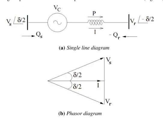
operating mode is capacitive and the current (magnitude) in the line is increased with resultant increase in power flow. On the other hand, if VC leads I by 90°, the operating mode is
inductive, and the line current is decreased. Since the losses are always present, the phase shift between I and VC is less than 90° (in steady state). We use the convention that the
reactive voltage lagging the current by 90° as positive (Fig. 2.a). According to this convention, the positive reactive voltage implies capacitive mode of operation while negative reactive voltage implies inductive mode of operation. Since δis close to 90° (Fig. 2.b).
(a)Single line diagram
(b) Phasor diagram
Figure 2. Representation of SSSC in a transmission line HV
Distance Protection for Transmission Line
Distance relays are normally used to protect transmission lines HV and EHV [15-17]. They respond to the impedance between the relay location and the fault location. As the impedance per mile of a transmission line is fairly constant, these relays respond to the distance to a fault on the transmission line - and hence their name. As will be seen shortly, under certain conditions it may be desirable to make distance relays respond to some parameter other than the impedance, such as the admittance or the reactance, up to the fault
The R-X diagram is an indispensable tool for describing and analyzing a distance relay characteristic, and we will examine it initially with reference to a single-phase transmission line. Similar principles are applicable in case of a three-phase transmission line, provided that appropriate voltages and currents are chosen to energize the distance relay [17-19]. This matter of energizing voltages and currents in three phase systems will be considered in detail later.
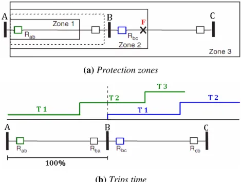
The setting zones of distance relays are open at the far end. In other words, the remote point of reach of a distance relay cannot be precisely determined, and some uncertainty about its exact reach must be accepted. This uncertainty of reach is typically about 5% of the setting. Referring to figure 3, the desired zone of protection is shown with a dotted line [19]. The ideal situation would be to have all faults within the dotted area trip instantaneously.
(a) Protection zones
(b) Trips time
Figure 3. Three zone step distance relaying to protect of transmission line HV
Measured Impedance by Distance Relay
The R-X diagram to both analyze and visualize the relay response. By utilizing only two quantities resistance R and reactance X (or Z and θ), we avoid the confusion introduced by using the three quantities voltage (Erelay) and current (Irelay) measured by distance relay.
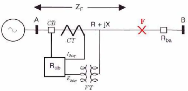
Consider an ideal fault at location (F) in the single-phase system shown in figure 4.
primary quantities.
Figure 4. Voltage and current as seen by the distance relay
In terms of the secondary quantities of voltage and current transformers, the relay sees the primary impedance (Zprim) as secondary impedance (Zsec) where:
Zsec = (Erelay / Irelay) = Zprim.(NCT / NVT) (2)
Where, Zsec is equal impedance measured by distance relay, NCT and NVT is Current and voltage transformer turns ratios.
Apparent Impedance Seen by Distance Relay Considering SSSC
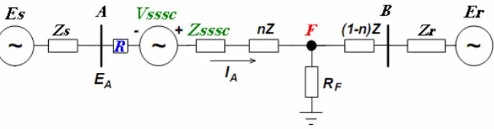
Consider the two machine test system illustrated in figure 5. It consists of one voltage sources (Es) and one voltage load (Er) and a transmission line between. Assume a SSSC
installed at the beginning of the transmission line. The distance relay (R) location is shown by busbar A as well.
Figure 5. Transmission line HV study with SSSC
Equivalent Circuit
power frequency model of the SSSC is considered. For the same reason, the distributed transmission line model could be replaced by a lumped resistance and reactance and the shunt capacitance can be neglected [8, 11]. The equivalent circuit of figure 6 with considering a fault at point Fis shown in figure 7.
Figure 6. Equivalent circuit of the transmission line HV study
We assume a voltage ratio (h) and a phase difference for Es and Er so that:
Er = Es.h.e-jδ, with 0 ≤δ≤ 90° (3)
where δ = Angle between Es and Er, and h is ratio of the magnitude of the line end voltages.
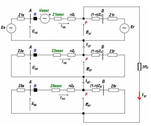
Ground Fault
For our study, we assume that single phase to ground fault occurred in phase A with
RF. The equivalent sequence circuit (positive, negative and zero) required for calculating the
apparent impedance seen by distance relay is shown in the figure above.
In order to calculate the impedance seen by distance relay [1, 17, 21] from figure 8 we have:
ZA = EA / (IA+ kEarth.IA0) (4)
with kEarth is earth factor and equal (Z0-Z1)/Z1;
where EA and IA are voltage and current measured in phase A.
Whereas for EA and IA we have the following general relations:
IA = I1A+ I2A+ I0A (6)
Figure 7. Sequence circuits in presence ground faults with fault resistance
According to the sequence circuits shown in figure 7 we have:
E1A = ES-Z1S.I1A (7)
E2A = -Z2S.I2A (8)
E0A = -Z0S.I0A (9)
By definition we set:
E1S’= E1S + n.Z1 + Z1SSSC (10)
E0S’= E0S + n.Z0 + Z0SSSC (12)
E1R’= (1-n).Z2 + Z1R (13)
E2R’= (1-n).Z2 + Z2R (14)
E0R’= (1-n).Z0 + Z0R (15)
where, Z1, Z2 and Z0 is impedance sequence of transmission line; Z1S, Z2S and Z0S is internal impedance sequence of source; Z1R, Z2R and Z0R is internal impedance sequence of load.
It must be denoted that in all above relations the positive and negative components of impedances are equal. In our problem, the components of the fault current are deduced as:
I1F = I2A = I0A= EFPF / (Z∑+3.RF) (16)
where,
Z∑= Z1eq + Z2eq + Z0eq (17)
Z1eq = Z2eq = Z1S’// Z1R’ = Z1S’.Z1R’ / (Z1S’+Z1R’) (18)
Z0eq = Z0S’// Z0R’ = Z0S’.Z0R’ / (Z0S’+Z0R’) (19)
where EFPF is pre-fault voltage; Z∑is total impedances seen from fault point; and RF is fault resistance.
The fault point pre-fault voltage is:
EFPF = Es - VSSSC - IPF.Z1S’ (20)
where IPF is pre-fault system current.
The pre-fault system current as following:
IPF = (Es - ER -VSSSC) / (Z0S’+Z1R’) (21)
Components of current IA we can derive:
I1A = (Es - E1F -VSSSC) / Z1S’ (22)
I0A = - E0F / Z0S’ (24)
If we define A1, A2,A3and A4as:
A1 = Z1R’ / (Z1R’ + Z1S’) (25)
A2 = Z0R’ / (Z0R’ + Z0S’) (26)
A3 = EFPF / (Z∑ + 3.RF) (27)
A4 = (ER / Z1R’) + (ES / Z1S’) (28)
Finally, from equation 5 and 6:
IA = (E2F / Z2S’)-A1[A4-2A3+ (VSSSC/Z1S’)] + A2.A3 (29)
EA = Es.[1-(E1S / Z1S’)] + A1.Z1S.[A4-2A3+(VSSSC/Z1S’)]- A2. Z0S.A3 (30) Finally equations for parameters measured by distance relay:
IRelay = IA/NCT (31)
ERelay = EA/NVT (32)
ZRelay = (NCT/NVT).ZA = RRelay+ jXRelay (33) The ZRelay measured by distance relay is only related to:
SSSC parameters (Vsssc, Zsssc, h and δ),
Fault condition (n and RF),
Sequence circuit parameters (positive, negative and zero),
Current and voltage transformer ratios.
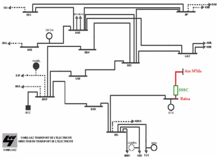
Case Study and Results
Figure 8. Eastern Algerian transmission networks 220 kV
The measured parameters, module and angle for IRelay, ERelay, resistance and reactance
for ZRelayfor a distance relay installed in Batna substationis calculating according to equations
(33,34 and35) using a MATLAB program. The impedances values of different elements study are detailed in Table 1.
The calculated parameters seen by distance relay for low variation of n with different values: 10, 25, 50, 75 and 100 % with fixed RF at 0.5 Ω, the resultants is shown in figure 9.
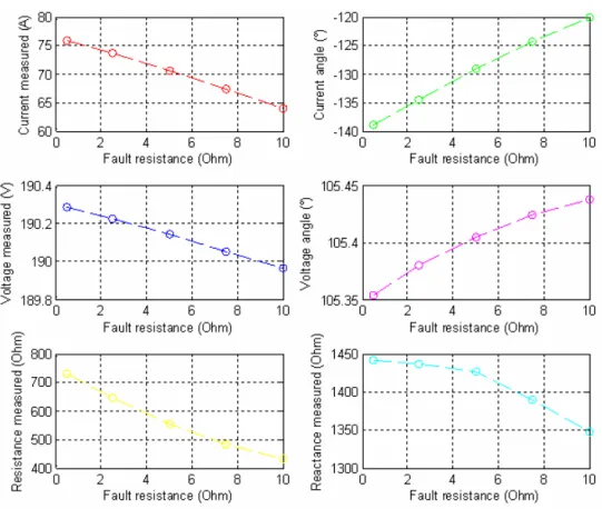
The calculated parameters seen by distance relay for low variation of RF with different
values: 0.5, 2.5, 5, 7.5 and 10 Ω with fixed n at 60%, the results are shown in figure 10.
The calculated parameters seen by distance relay for high variation of RF with
different values 50, 75, 100, 125 and 150 Ω with fixed n at 60%, the resultants is shown in figure 11.
Table 1. Impact of different factors on measured values by distance relay
Element Value
Source Z1s = 3.495+ j 16.150 Ω
Z0s = 9.754+ j 36.923 Ω
Load Z1r = 2.725+ j 5.284 Ω
Z0r= 6.125+ j 14.918 Ω
Transmission line Z1= 0.1236 + j 0.3140 Ω/km
Zo= 0.3181 + j 1.1121 Ω/km
SSSC Q = ±50 MVar, Un = 6.6 kV
C = 20 mF, VDC= 1 kV
Seriestransformer Un = 6.6/220 kV, STR = 50 MVA
ZTR = 0.0242+ j 0.1571Ω
Current and voltage transformer
NCT = 1500
Figure 9. Values measured for variation of n
Figure 11. Values measured for variation of high RF
Discussion
Figure 9, 10 and 11 show the measured voltage, current and measured resistance according tot the distance fault point (n) and fault resistance (RF) variation.
It can be noticed that the increase of distance fault point has a direct impact on the values measured by the protection relay. In fact increasing (n) results in increasing magnitude and angle of the voltage while reduction in magnitude and angle of current as well as reduction in. resistance and reactance.
From figure 10, it can be noticed that for low resistance, the increase of fault
resistance also has a direct impact on the measured values. When fault resistance (RF) is
increased voltage magnitude and current magnitude are decreased while their angles increase. The measured resistance and reactance also decrease.
magnitude of voltage and current while the voltage angle decrease compared to current angle which increase. Also it can be seen that for high resistance fault measured resistance increase while measured reactance decrease.
Thus there is no risk of tripping the circuit breaker in case of low fault resistance variation while there is a great risk of tripping the circuit breaker in case of high resistance variation.
Conclusions
This paper investigate the impact of Static Synchronous Series Compensator (SSSC) on the measured impedance (ZRelay) taking into account the distance fault point (n) and fault
resistance (RF). Various results were found for an actual line model of series compensated
electrical transmission lines 220 kV.
The measured impedance at the relaying point in the presence of SSSC for variation in the fault conditions n and RF with highand low values are examined. The study show the
importance of the parameters influence in avoiding open circuit breaker without fault for calculating a good setting of distance protection zones. This variation have a direct influence on the value of resistance and reactance measure by distance relay which have influence from the settings point of view of protection zones .
References
1. Padiyar K.R., FACTS Controllers in Power Transmission and Distribution, UK, New Age International Publishers, 2007.
2. Stanley H.H., Arun G.P, Power System Relaying, England, John Wiley & Sons Limited andResearch Studies Press Limited, third edition, 2008.
3. El-Arroudi K., Joos G., McGillis D. T., Operation of Impedance Protection Relays with the STATCOM, IEEE Transactions on Power Delivery, 2002, 17(2), p. 381-387.
Transmission Systems, IEEE Transactions on Power Delivery, 2000, 15(1), p. 38-4.
5. Kazemi A., Jamali S., Shateri H., Distance Relay Mal-Operation due to Presence of SSSC on Adjacent Lines in Inter phase Faults, IEEE Region 5 Conference, Kansas City, MO, USA, 17-20 April 2008.
6. Zhou X., Wang H., Aggarwal R. K., Beaumont P., Performance Evaluation of a Distance Relay as Applied to a Transmission System with UPFC, IEEE Transactions on Power Delivery, 2006, 21(3), p. 1137-1147.
7. Albasri F.A, Sidhu T.S., Varma R.K., Performance Comparison of Distance Protection Schemes for Shunt-facts Compensated Transmission Lines, IEEE Transactions on Power Delivery, 2007, 22(4), p. 2116-2125.
8. Khederzadeh M., Ghorbani A., Salemnia A., Impact of SSSC on the Digital Distance Relaying, IEEE Power & Energy Society General Meeting, Calgary, 26-30 July 2009.
9. Sidhu T.S., Khederzadeh M., TCSC Impact on Communication Aided Distance Protection Schemes and its Mitigation, IEE Generation, Transmission and Distribution, 2005, 152(5), p.714-728.
10. Khederzadeh M., Sidhu T. S., Impact of TCSC on the Protection of Transmission Lines,
IEEE Transaction on Power Delivery, 2006, 21(1), p. 80-87.
11. Rastegar H., Khansaryan A.P., A New Method for Adaptive Distance Relay Setting in the Presence of SSSC using Neural Networks, 1st IEEE Conference on Industrial Electronics and Applications (ICIEA), Marina Mandarin, Singapore, 24-26 May 2006.
12. Gyugyi L., Dynamic Compensation of AC Transmission Lines by Solid-state Synchronous Voltage Sources, IEEE Transactions on Power Delivery, 1994, 9(2), p. 904-911.
13. Gyugyi L., Schauder C.D., Sen K.K., Static Synchronous Series Compensator: a Solid State Approach to the Series Compensation of Transmission Lines, IEEE Transactions on Power Delivery, 1997, 12(1), pp. 406-417.
14. Sen K.K., SSSC-Static Synchronous Series Compensator: Theory, Modeling and Applications, IEEE Transactions on Power Delivery, 1998, 13(1), p. 241-246.
IEEE Transaction on Power Apparatus and Systems, 1979, 98(1), p. 246-256.
16. Mason C.R., The Art and Science of Protective Relaying, New York, USA, John Wiley & Sons, Inc, 1956.
17. Blackburn J.L., Domin T.J., Protective Relaying: Principals and Applications, USA, Taylor & Francis Group-CRC Press, Third edition, 2006.
18. Jackson L., Power System Protection, Volume 2: Systems and Methods, London-United Kingdom, The Institution of Electrical Engineers and Electricity Association Services Limited, 2005.