Printed in Brazil - ©2004 Sociedade Brasileira de Química 0103 - 5053 $6.00+0.00
A
r
ti
c
le
* e-mail: [email protected]
Experimental Design Employed to Square Wave Voltammetry Response Optimization for the
Glyphosate Determination
Reinaldo F. Teófiloa, Efraim L. Reis*,a, César Reisa, Gilmare A. da Silvaa and Lauro T. Kubotab
a
Departamento de Química, Universidade Federal de Viçosa, 36570-000 Viçosa - MG, Brazil
b
Instituto de Química, Universidade Estadual de Campinas, 13083-970 Campinas - SP, Brazil
A corrente de pico de redução do derivativo N-nitroso do herbicida glifosato foi otimizada por planejamentos experimentais, para sua determinação. As variáveis envolvidas na otimização da voltametria de onda quadrada (SWV) foram: incremento de voltagem, amplitude, freqüência, concentração do eletrólito de suporte e a área da gota de mercúrio. Um planejamento fatorial completo 25 foi usado para avaliar os efeitos das variáveis. Dos resultados obtidos foram escolhidos três dos
fatores mais importantes. Estas variáveis foram estudadas com o planejamento composto central. As condições que proporcionaram a melhor resposta voltamétrica foram: 0,025 volt, 0,125 volt, 70 Hz, 1,25 mol L-1 e 0,60 mm2 para o incremento de voltagem, amplitude, freqüência, concentração do
eletrólito e área da gota de mercúrio, respectivamente. Nestas condições a faixa operacional foi de 0,050 a 100,0 µg mL-1, os limites de detecção e quantificação foram de 0,025 e 0,080 µg mL-1,
respectivamente.
The reduction peak current of the derivative N-nitroso of glyphosate herbicide was optimized by experimental design for their determination. The variables involved in the optimization of the square wave voltammetry (SWV) were: voltage step, amplitude, frequency, concentration of the supporting electrolyte and the area of the mercury drop electrode. A complete 25 factorial design was used to
evaluate the effects of the variables. From the results obtained by the factorial design was set the three more important factors. These variables were evaluated with a central composite design. The conditions that proportionate the best voltammetric response were: 0.025 volt, 0.125 volt, 70 Hz, 1.25 mol L-1
e 0.60 mm2 for step voltage, amplitude, frequency, electrolyte concentration and area of the mercury
drop, respectively. In these conditions the operational range was from 0.050 up to 100.0 µg mL-1, the
detection and quantification limits were 0.025 and 0.080 µg mL-1, respectively.
Keywords: glyphosate, SWV, experimental design, voltammetry
Introduction
The aminoacid, phosphonated glyphosate (N-(phophonomethyl) glycine) is a non-selective herbicide, systemic, pos-emergent reported by Baird et al.1 in 1971
and commercialized in 1973. The glyphosate selling represents about 60% of all herbicide in the world, reaching a total amount of US$ 1200 millions per year. Due to its action in a wide spectrum of weeds, is the herbicide most used in the world.2,3 Nowadays, some cultures have been
become more resistant with the biotechnological improvement leading an increase in the consumption in about 20% at year.2
The extensive using of this herbicide is worrying the environmentalists, although the world health organization
(WHO) affirms that there is no evidence in the carcinogenicity in mammals. However, the effects in the environment in flora or microbiological population in soil are pernicious.1,4 This situation can get worse due to its
accumulation. In this point of view, is very important to study physico-chemical properties of the herbicide and its interaction with the environment, as well as the detection, extraction and quantification in natural samples.3
Recent works published about glyphosate determination using HPLC,5 ion exchange chromatography
coupled with a pulsed amperometric detector,6 ion
chromatography7 and gas chromatography coupled to
mass spectrometry8 are expensive and take long analysis
time.
and can be determined voltammetrically.10 Bronstad and
Friestad11 showed the possibility to determine glyphosate
by differential pulse polarography as a rapid and reasonable sensitive method. Therefore, no method using square wave voltammetry has been described to determine glyphosate. Barker proposed the SWV in 1952,12 but only after
electronic advances the technique became more popular. The SWV is rapid, sensitive and consumed less analyte than the other pulsed techniques.13 The sensitivity of the
voltammetric techniques can be improved using chemometric tools, such as factorial design, methods for surface of response14 or by sequential simplex method.15
Factorial designs are very useful for preliminary investigations to determine factors that have influence or no on the response, but not to describe the influence strict way.16 The factorial design is more efficient to evaluate
the interaction between the variables, which is very important to looking for the optimal conditions.17 After
the knowledge obtained with this study, a more detailed investigation about the surface of response of the system can be performed.16,18
The surface of response method of optimization is based on the use of factorial design being represented by a graphic of the response of the system at a function of the factors. The surface of response is an easy form to visualize how the factors affect in the measures of the system.18
The optimization of the sensitivity of SWV for glyphosate determination using factorial design and method of surface of response is described.
Experimental
Chemicals
Glyphosate 99.9% pure was acquired form Monsanto Co., Hydrochloric acid 37% from Merck®, sodium nitrite
from Synth® e ammonium sulphamate from Sigma® were
used as received. The 1.0 mg mL-1 glyphosate solution
and 0.10 g mL-1 ammonium sulphamate were prepared and
stored, because they are stable for long time at room temperature. The 10.0 mg mL-1 sodium nitrite was freshly
prepared before use due to its easy oxidation.
Instrumental
The voltammetric measurements were carried out in a polarography with 757 VA Computrace Stand (Metrohm®
Ltd. CH-9101 Herisau Switzerland) working with a hanging mercury drop electrode (HMDE), as working electrode, a Ag/AgCl as reference and a platinum as counter. The data were acquired and treat with VA Computrace 1.0134
software. Data analysis was achieved with STATISTICA software (version 6.0, StatSoft, Inc.).
Glyphosate derivatization
The preparation of the 500 µg mL-1 glyphosate
derivatized solution was performed adding 50.0 mL of the stock solution, 20.0 ml of 5.0 mol L-1 HCl and 5.0 mL of
10.0 mg mL-1 sodium nitrite into 100.0 mL volummetric
balloon, waiting 15 min to complete the reaction. After that, 5.0 mL of 0.10 g mL-1 ammonium sulphamate, to
consume the nitrite excess, and the volume was completed with deionized water.
Optimization procedure and chemometric treatment
The following procedures were carried out to the voltammetric response optimization: (i) 10.0 mL of the supporting electrolyte was transferred to the electrochemical cell and nitrogen was bubbled for 300 seconds in the first step, and 30 seconds in the successive steps. The nitrogen flow was kept on the solution during the measurements. (ii) The equilibrium time was set up to 10 s, before the cathodic sweeping between –0.5 and –0.9 V for the blank and after the standard solution addition (100 µL) 500 µg mL-1 of nitrosamined glyphosate. The
instrument was set up to carry out three scanning for each assay. The assays were performed in a random way at room temperature. The data were processed in the software Matlab and Statistic for obtaining the effects and surface of response.
Voltammetric parameters
The aim of the factorial design is the verification of the parameter influence on the response. Hydrochloric acid was used as supporting electrolyte based on the studies carried out by Friestad and Bronstad.11 The factors voltage
step (volts), frequency (Hz) and the pulse amplitude (volts), which are instrumental parameters, were chosen according to the literature.14,15 The levels of these factors were obtained
in a previous study. The stepwise time (s) parameter is the inverse of the frequency, while scan rate is the result of the product between stepwise and frequency. The surface area (mm2) of mercury drop was also chosen as a factor to be
analyzed in the factorial design. The purging time, additional purging and equilibrium time were fixed in 300, 30 and 15 seconds, respectively. Hence, a complete 25
analysis by surface of response employing a central composite design (CCD).
Results and Discussion
Study of the levels of voltammetric parameters
The levels of voltage step (VS), frequency (Fr) and amplitude (A) for the factorial design were established from the univariate study. The results are shown in Figures 1-3. The increase in the voltage step (VS) until 0.05V contributed to enhance the voltammetric response (Figure 1), however from 0.03V the symmetry of the voltammograms is lost and, for values higher than 0.05V a decrease in the response is observed. Thus, the levels chosen for this factor were 0.01 and 0.02V. The increase in the amplitude (A), (Figure 2), cause an increase in the
response, however for values higher than 0.10 V a shift in the peak potential towards more positive values was observed, thus the levels of 0.05 and 0.10 V was employed in the factorial design.
The increase in the frequency (Fr) of the pulse provoked by the increase in the current values in all studied extension (Figure 3), but for values higher than 90 Hz an instrumental incompatibility was observed when utilized with the levels chosen for other factors (A and VS). The chosen levels for this factor were 50 and 90 Hz. A complete factorial design 25, with the levels presented in Table 1 were performed
with the aim to establish the degree of influence for each factor on the response and verify the existence of interaction factors. The effects observed by the studied factors on the response, as well as those caused by the interactions between the factors are shown in Table 2.
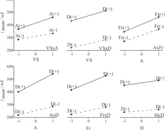
It is observed that all variables influence on the voltammetric response in the positive way, e.g. when their levels is increased individually, the current also increase. The main effects of the factors confirm this behavior. Besides the main effects, it is possible to verify that all effects of second order interactions are synergic. This means that changing the level of one-factor influences the effect caused by other variable in a positive way. Figure 4 shows the graphical representation of these effects.
Table 1. Factors and levels selected to the factorial design
Factors Levels
- +
Voltage Step - VS (V) 0.01 0.02
Amplitude - A (V) 0.05 0.10
Frequency - Fr (Hz) 5 0 9 0
Electrolyte Concentration - H (mol L-1) 0.5 1.0
Drop Size– D (mm2) 0.27 0.60
Figure 2. Effect of the amplitude (A) parameter on the SWV signal, with voltage step (VS) and frequency (Fr) fixed in 0.01 volt and 50 hertz, respectively.
Figure 1. Effect of the voltage step (VS) parameter on the SWV signal, performed with amplitude (A) and frequency (Fr) fixed in 0.05 volt and 50 hertz, respectively.
The interaction VSxA, means that when the amplitude factor (A) varies from the level (-) to (+), keeping the voltage step (VS) in its level (-), the average of response is lower than the same variation of amplitude levels, within the level (+) of VS. Presumably, the increase in the current, when the values of factors is shifted toward (+) level, is due to the increase in the total value of the applied pulse, which contributes to an abrupt polarization of the electrode and by the effective electron transfer with the glyphosate molecules.
In the same way, when the frequency factor (Fr) is varied to highest value of its level, within the positive level of amplitude factor (A), the obtained average response is
higher than the response obtained with the same variation in the negative level of amplitude factor. An increase in the electrode polarization decreasing the interval of the reading time can be the responsible by the increase. However, the contribution of capacitive current, when higher frequencies are used, is more pronounced and the interpreted current is the combination of the faradic and capacitive current, which can contribute to appear a systematic error in the determination and, also diminish the peak symmetry, that is not desirable. The surface area of the mercury drop (D) was the factor that most influenced on the response, presenting the higher value for the principal effect and was present in the interaction factors of second, third, fourth and fifth order. The interaction effectsVSxD, AxD, FrxD and HxD demonstrated the importance the drop area to perform the reduction reaction of the nitrosamined glyphosate. In this process, the increase in the level of D factor, within the (+) level of other factors, provided a higher average response than the average obtained in the (-) level of these same factors. However, an excessive increase in the drop area contributes to an increase in the both faradic and capacitive current making up the results. The negative interaction effect VSxFrxD
indicates that exist an incompatibility between the increase of scan rate and polarization using drop with large area, within the levels studied. The increase in the scan rate does not favor the electron transfer on the electrode surface provoking and increase in the capacitive current density in relation to the faradic current. The same can be happening when the interaction effects VSxFrxHxD and
VsxAxFrxHxD are analyzed. Although, negative effects occur in high orders the increase in the drop area causes a global increase on the response due to the principal and second order effects, thus this factor should be fixed at 0.6 mm2, the maximum allowed in the instrument. The
frequency factor was fixed in a medium value between highest and lowest levels, at 70 Hz, due to its influence on the capacitive current generation for higher frequencies. This way, the set factors for the design to the surface response were the step voltage, amplitude and concentration of supporting electrolyte.
Response surface study: central composite design
Table 3 shows the variables utilized in the central composite design to the analysis of response surface with its respective values. The values of frequency (Fr) and drop size (D) were fixed in 70 Hz and 0.6 mm2, respectively.
The analysis of variance (ANOVA) for the fitted linear model to the experimental data is shown in Table 4. The significant F-test to the regression indicates that the model
Table 2. Significant effects and errors to the studied factors in 25
factorial design
Effect evaluation ± standard error t-testb
Mean 362.27 ± 2.20 164.30
Principalsa
V S 70.59 ± 4.41 16.00
A 105.34 ± 4.41 23.88
Fr 85.04 ± 4.41 19.28
H 29.86 ± 4.41 6.77
D 219.79 ± 4.41 49.84
Interactions
VS x A 22.83 ± 4.41 5.17
VS x D 10.03 ± 4.41 2.27
A x Fr 10.24 ± 4.41 2.32
A x D 36.37 ± 4.41 8.25
Fr x D 27.47 ± 4.41 6.23
H x D 8.87 ± 4.41 2.01
VsxAxD 14.73 ± 4.41 3.34
VSxFrxD -15.61 ± 4.41 -3.54
VSxAxHxD 9.62 ± 4.41 2.18
VSxFrxHxD -11.52 ± 4.41 -2.61
VSxAxFrxHxD -14.48 ± 4.41 -3.28
a Statistically significant values of Student’s t-test; b ttab = t
λ,a = 1.998
(ν = 64 and α = 0.05).
describes the behavior of the variables in the studied experimental range and at least one of the variables is significantly influencing the response. The non-significant
F-test to the lack-of-fit certifies the fit quality of the cited model.
The equation of the linear model only consisting of the significant coefficients with α = 0.05, by t-test is shown below:
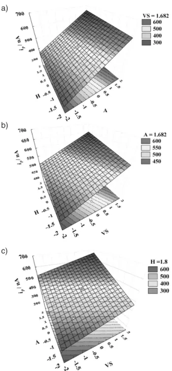
According to the regression equation, the amplitude factor, here represented by A variable, is emphasized because its coefficient value, this way the major factor of influence in the response. It is impossible to obtain the response surface directly from the model because it presents four variables being necessary, in consequence, four dimensions. In this case were fixed two levels to each one of the independent variables, alternating the levels of the others. The fixed levels corresponded to the higher and lower of the design obtaining two response surfaces to each fixed level. Table 5 lists the equations generated replacing each fixed level to each variable and the maximum response value reached, in the experimental range, corresponding to each equation.
The maximum response values, ordered in Table 5, were provided by the graphical analysis of the surface related
Table 3. Levels involved in the experimental design to the analysis of the response surface
-1.682 -1.600 - 1 0 1 1.682 1.800
VS (volt) 0.0066 - 0.01 0.015 0.02 0.023
-A (volt) 0.033 - 0.05 0.075 0.1 0.117
-H (mol L-1) - 0.35 0.5 0.75 1.0 - 1.2
Table 4. ANOVA to the linear model
Source SSa DFb MSc F F
tab(α = 0.05)
Regression 104813.2 3 34937.73 52.10 3.34
Residuals 9387.4 1 4 670.53
Lack-of-fit 8406.2 1 1 764.2 2.34 8.77
Pure error 981.2 3 327.07
Total 114200.6 1 7
aSum of squares; bDegrees of freedom; cMean squares% explained variance = 97.09 -% maximum of the explained variance = 99.12.
Table 5. Models and responses obtained to the parameters with the fixed levels
Factor Fixed level Regression equation Graphic (Figure 5)
V S 1.682 îp = 471.28 + 76.42 A + 18.70 H A
A 1.682 îp = 535.10 + 38.49 VS + 18.70 H B
H 1.80 îp = 440.19 + 38.49 VS + 76.42 A C
to each equation (Figure 5). The voltage step (VS) and supporting electrolyte (H) concentration factors, provide higher values in the response when are found in its higher levels. In this way, the optimization process using a 25
factorial design and analyses by response surface, allowed estimate the factor values that provide better responses. Table 6 lists the parameters with its respective values that optimize the voltammetric determination of the glyphosate herbicide. The estimated current value by the regression equation, according to the optimized conditions, was
ipo = 600 nA. The current observed experimentally was
ipe = 593.72 nA being both for a 5.0 µg mL-1 glyphosate
nitrosamined solution. Thus, the relative error was only -1.06%.
Linearity and limits
The methodology for the glyphosate determination using square wave voltammetry was studied in two linear ranges (Figure 6), one between 0.05 µg mL-1 and 1.75 µg mL-1
and other between 1.0 µg mL-1 a 100.0 µg mL-1 using the
optimized conditions listed in Table 6. The voltammograms obtained for lower concentrations than 1.0 µg mL-1 presented
Table 6. Optimized parameters to the glyphosate determination by square wave voltammetry
Parameters Optimized values
Start potential -0.5 V
End potential -1.05 V
Voltage step 0.025 V
Amplitude 0.125 V
Frequency 70 Hz
Scan rate 1.752 Vs-1
Drop size 0.60 mm2
Supporting electrolyte, HCl 1.25 mol L-1 Figure 5. Three-dimensional response surfaces obtained from the regression equation. Codified values to VS, A and H.
according to Morrison et al.19 obtaining values of
25.0 µg L-1 and 80.0 µg L-1, respectively.
Conclusions
The obtained results show that using factorial design to optimize voltammetric parameters to the glyphosate determination enhances the response increasing the sensitivity in a significant way. The linear response range was also improved and amplified. The sensitivity of the square wave voltammetry with chemometric optimization was comparable with those observed for the chromatographic ones. For the real samples the cleaning, preconcentration and derivatization steps are simpler and faster, comparing to the chromatographic methods. Considering the cost of the instrumentations and chemicals the electrochemical technique is much lower than the chromatographic ones.
Acknowledgments
The authors thank CAPES for the financial support and Geochemistry Laboratory of the “Escola de Minas da Universidade Federal de Ouro Preto” for the instrumental support.
References
1. Carlisle, S.M.; Trevors, J.T.; Water, Air and Soil Pollution
1988, 39, 409.
2. Amarante Júnior, O.P.; dos Santos, T.C.R.; Brito, N.M.; Ribeiro, M.L.; Quim. Nova2002, 25, 589.
3. Amarante Júnior, O.P.; dos Santos, T.C.R.; Brito, N.M.; Ribeiro, M.L.; Quim. Nova2002, 25, 420.
4. Morrison, M.L.; Meslow, E.C.; For. Sci.1984,30, 95. 5. Stalikas, D.C.; Konidari, C.N.; J. Chromatogr. A2001, 907, 1. 6. Sato, K.; Jin, J.; Takeuchi, T.; Miwa, T.; Suenami, K.; Takekoshi,
Y.; Kanno, S.; J. Chromatogr. A2001, 919, 313.
7. Zhu, Y.; Zhang, F.; Tong, C.; Liu, W.; J. Chromatogr. A1999,
850, 297.
8. Borjesson, E.; Torstensson, L.; J. Chromatogr. A2000, 886, 207; Royer, A.; Tabet, J.C.; Hulot, S.; Reding, M.A.; Communal, P.Y.; Anal. Chem.2000, 72, 3826.; Stalikas, C. D.; Pilidis, G. A.; J. Chromatogr. A2000, 872, 215; Kudzin, Z. H.; Gralak, D. K.; Drabowicz, J.; Luczak, J.; J. Chromatogr. A2002,
974,129.
9. Marsh, J.; Advanced Organic Chemistry: Reactions,
Mechanisms, and Structure, 14th ed.; Wiley: New York, 1992.
10. Smyth, W.F.; Watkiss, P.; Burmicz, J. S.; Hanley, H. O.; Anal. Chim. Acta1975, 78, 81.
11. Bronstad, J.O; Friestad, H.O.; Analyst1976, 101, 820; Friestad, H.O; Bronstad, J.O.; J. Assoc. Off. Anal. Chem.1985, 68, 76. 12. Barker, G.C.; Jenkins I.L.; Analyst1952, 77, 685.
13. Brett, C.M.; Brett, A.M.O.; Electrochemistry: Principles,
Methods, and Applications, Oxford University Press Inc: New York, 1993.
14. Ruiz, B.L.; Frutos, G.; Pedrero, P.S.; Martín, J.P.; Analyst 1993, 118, 59; Alonso, M.A.; Sanllorente, S.; Sarabia, L.A.; Arcos, M.J.; Anal. Chim. Acta 2000, 405, 123; Furlanetto, S.; Orlandini, S.; Aldini, G.; Gotti, R.; Dreassi, E.; Pinzauti, S.;
Anal. Chim. Acta2000, 413, 229.
15. Oduoza, C.F.; Chemom. Intell. Lab. Syst.1992, 17, 243. 16. Neto, B.B.; Scarminio, I.S.; Bruns, R.E.; Como Fazer
Experimentos; 2th ed., Editora Unicamp: Campinas, 2002.
17. Box, G.E.P.; Hunter, W.G.; Hunter, J.S.; Statistic for Experimenters: An Introduction to Design, Data Analysis and
Model Building, Wiley: New York, 1978.
18. Myers,R.H.; Montgomery, D. C.; Response Surface
Methodology, Wiley: New York, 1995. 19. Morrison, G.H.; Anal. Chem.1980, 52, 2241.
Received: March 20, 2004
Published on the web: October 25, 2004