22 Ayman Al Sawalha and Inas Al Mubarak
Effect of Warm Ionized Plasma Medium on Radiation Properties of Four Elements Microstrip
Antenna Array Printed on Ferrite Substrate
Ayman Al Sawalha and Inas Al Mubarak
Physics Department, Faculty of Science, King Faisal University, P.O.Box 400, Al-Hassa, Saudi Arabia
(Received on 21 July, 2009)
This paper describes theoretically the radiation properties of four element microstrip antenna array printed upon a typical ferrite substrateNi1.062Co0.o2Fe1.948O4in the presence of normal dc magnetic bias field. In loss-less isotropic warm plasma, this array antenna geometry excites both electromagnetic (EM) and electroacoustic plasma (P) waves in addition to nonradiating surface waves. In the absence of an external magnetic field, the EM – mode and P-mode can be decoupled into two independent modes, the electoacoustic mode is longitudinal while the electromagnetic mode is transverse. Far zone electromagnetic mode and plasma mode radiation fields are derived using vector wave function technique and pattern multiplication approaches. The results are obtained in both plasma medium and free space .Some important antenna parameters such as radiation patterns, radiation conductance and directivity are plotted for different values of plasma to source frequency.
Keywords: Microstrip Antenna Array, Ferrite, Plasma Medium
Introduction
Microstrip antennas are proved useful for application on spacecrafts and mobile handsets due to their lightweight, small size, better aerodynamic properties and compatibility to get integrated with host objects. In past years, extensive research on different geometries of microstrip antennas un-der different conditions has been carried out to improve their inherent low bandwidth and low directive gain [1].
Ferrite and other magnetic materials have been extensively used in several microwave devices such as phase shifters, iso-lators, circuiso-lators, tunable filters, delay lines etc. Ferrite ma-terials basically have a significant amount of anisotropy at microwave frequencies [2].This anisotropy induces on apply-ing external dc magnetic field and brapply-ings about nonreciprocal behavior in them. Availability of low cost commercial ferrite substrates and recent advances in thin film technology has attracted noticeable attention of scientific community in the development of microstrip antennas on ferrite substrates [3-4].
The high dielectric constant of the ferrite substrate re-duces the antenna dimensions and when biased with DC magnetic field, the antenna exhibits a number of novel prop-erties. These include frequency tuning agility, the genera-tion of circular polarizagenera-tion, reducgenera-tion of surface waves and radar cross-section control. Microstrip antenna mounted on aerospace vehicles encounter plasma medium during their voyage in space, as a result of which radiation properties are altered significantly. This change is caused due to the gener-ation of electroacoustic waves in addition to electromagnetic waves [5-7].
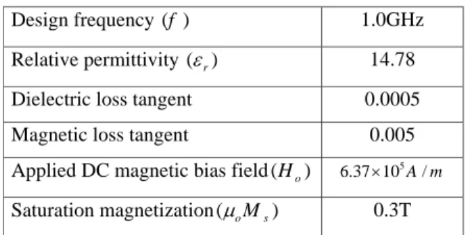
This paper reports theoretical work carried out to in-vestigate the radiation properties of four element mi-crostrip antenna printed upon a typical ferrite substrate Ni1.062Co0.o2Fe1.948O4 by considering the presence of dc magnetic bias field normal to the direction of propagation of electromagnetic waves. Several radiation characteristics of four element microstrip antenna array are analyzed the-oretically by applying cavity modal based modal expansion technique. Design requirement and substrate characteristics considered for this theoretical analysis are listed in table 1.
TABLE I: Design requirement and characteristics of
Ni1.062Co0.o2Fe1.948O4.
Design frequency ( )f 1.0GHz
Relative permittivity ( )εr 14.78
Dielectric loss tangent 0.0005
Magnetic loss tangent 0.005
Applied DC magnetic bias field(Ho) 5
6.37 10× A m/
Saturation magnetization(µoMs) 0.3T
Theoretical Considerations
Microstrip antennas printed on ordinary non-magnetic di-electric substrate with a single feed point have a single lin-earity polarized resonance mode. By applying two orthogo-nal feeds with 90 phase difference, a microstrip antenna will again have a single dominant resonance mode but can radi-ate circularly polarized waves. The use of magnetized fer-rite substrate in place of dielectric substrate however leads to quite different results, since it can support various guided modes in different conditions. When direction of magnetiza-tion is normal to the direcmagnetiza-tion of propagamagnetiza-tion of electromag-netic waves, two plane wave modes namely ordinary (O) and extraordinary (E) modes exist. The propagation constant in this case is still given by
δ=α+jβ=jωpε
oεrµoµe f f. . . (1) The ordinary wave is similar to plane wave in a dielec-tric slab polarized transversally to the biasing direction with phase constant [8].
βO= 2πfr
c
√
εr. . . (2) However extraordinary wave is a transverse electric mode polarized parallel to the biasing direction with phase con-stant:
βE= 2πfr
c
p
Brazilian Journal of Physics, vol. 40, no. 1, March, 2010 23
The effective permeability of a magnetized substrate material (µe f f)is given by [9]:
µe f f=
µ2−K2
µ . . . (4)
With
µ=1+ ωoωm ω2
o−ω2m
and K= ωωm ω2−ω2
m
. . . . (5)
Hereωoandωmare the precession and forced precession frequencies respectively and are defined as:
ωo=µoγHo , ωm=µ0γMs and ω=2πf Applied dc magnetic bias field (Ho)and saturation magne-tization (µoMs) are considered in Amper/meter (A/m) and Tesla (T) units, respectively.
Whenµe f fis negative, the extraordinary wave is decaying even if the material is loss-less. The frequency range for negativeµe f f ispω0(ωo+ωm)≤ω ≤ (ωo+ωm).
The geometry and coordinate system of four element mi-crostrip antenna array of rectangular mimi-crostrip patch an-tenna are shown if figure (1).
FIG. 1: Geometry and coordinate system of four element microstrip antenna array.
In microstrip antenna array each patch is excited in a same phase and amplitude by corporate microstrip line feed con-nected to the edge of the radiating slot [10].
Radiation Field Expressions
Using hydrodynamic theory and vector wave function technique [11-12], the total far field of electromagnetic mode and plasma mode of the linear array are obtained as:
EM mode:
(Eφ)T=−jVπoβeLe
−jβer
r sinθ sin(βeh
2 cosθ)
(βeh
2 cosθ)
sin(βeL
2 sinθsinφ)
(βeL
2 sinθsinφ)
cos(βeL
2 sinθcosφ)
sin 2(βedsinθsinφ)
sin12(βedsinθsinφ)
. . . .
(6)
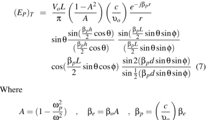
And in plasma mode:
(EP)T = VoL
π
1−A2 A
c υo
e−jβpr
r
sinθsin( βph
2 cosθ) (βph
2 cosθ)
sin(βpL
2 sinθsinφ) (βpL
2 sinθsinφ) cos(βpL
2 sinθcosφ)
sin 2(βpdsinθsinφ) sin12(βpdsinθsinφ)
(7) Where
A= (1−ω
2 p
ω2) , βe=βoA , βp=
c υo
βe
βe,βpare the propagation constants in electromagnetic mode and plasma mode respectively andAis the plasma parameter.
Radiated Power
The radiated power in the EM mode is obtained by inte-grating the Poynting vector over a large sphere. In our case study:
Pe= A 2zo
(βeLVo
π )
2I1. . . ..
(8) Where
I1 = Z π
2
0 Z 2π
0 [
sin(βeh2cosθ) (βeh2cosθ) sin(βeL2sinθcosφ)
(βeL2sinθcosφ)
sinθcos(βe L
2sinθcosφ) sin 2(βedsinθsinφ)
sin12(βedsinθsinφ)
]2sinθdθdφ SimilarlyPpis obtained as
Pp= L2β
pVo2 π2ε
oωzo (1−A
2
A2 )I2. . . .. (9) Where
I2 = Z π
2
0 Z 2π
0
[sin(βp h 2cosθ) (βph2cosθ)
sin(βpL2sinθcosφ) (βpL2sinθcosφ) cos(βp
L
2sinθcosφ) sin 2(βpdsinθsinφ) sin12(βpdsinθsinφ)
]2sinθdθdφ The EM mode radiation conductance is given by:
Ge= 2Pe V2 o
. . . . (10)
And the plasma mode radiation conductance is given by: Gp=
2Pp V2 o
. . . (11)
The directive gain of the antenna in plasma medium can be expressed as:
D=4πU(θ,φ) Pe
24 Ayman Al Sawalha and Inas Al Mubarak
Where,U(θ,φ)is the radiation intensity in(θ,φ)direction. The expression for directive gain of four element array
D=4πS I1
Where
S =
"
sin(βeh2cosθ) (βeh2cosθ)
sin(βeL2sinθcosφ) (βeL2sinθcosφ) sinθcos(βe
L
2sinθcosφ)
sin 2(βedsinθsinφ) sin 0.5(βedsinθsinφ)
2
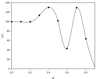
Using equations (8) and (9), the radiation efficiency of a ferrite-based four element microstrip antenna array inside plasma medium is expressed as:
η= Pe Pe+Pp×
100 %. . . . (13) The value of radiation conductance , directive gain and ef-ficiency of four element microstrip antenna array is com-puted for different values of plasma parameter withHo= 6.37×10⁵A/mand plotted in figures (2,3,4 and 5) respec-tively.
A
0.0 0.2 0.4 0.6 0.8 1.0
Ge
(m
h
o
)
0 1e-5 2e-5 3e-5 4e-5 5e-5 6e-5
FIG. 2: Radiation conductance in EM mode for different A and
Ho=6.37×10⁵A/m
Conclusion
The radiation properties of four element linear mi-crostrip antenna array printed upon a typical ferrite substrate Ni1.062Co0.o2Fe1.948O4have been studied by considering the presence of dc magnetic bias field normal to the direction of propagation of electromagnetic waves It is observed that the radiation conductance(Ge)of four element array is more than that of single element for all the plasma frequency. It is maxima in free space and decreases on increasing plasma frequency. It is found that when microstrip antenna is biased the directivity and the efficiency are improved as compared to an unbiased case. Our results are consistent with the re-sults reported by Yang [2]. Finally, it is concluded that the four element microstrip antenna array has unique radiation
A
0.0 0.2 0.4 0.6 0.8 1.0 Gp
X 10
-6
-40 -30 -20 -10 0 10
FIG. 3: Radiation conductance in P-mode for different A andHo=
6.37×10⁵A/m
A
0.0 0.2 0.4 0.6 0.8 1.0
De
(d
B
)
1 2 3 4 5 6 7 8
FIG. 4: Directivity in EM mode for different A andHo=6.37×
105A/m
A
0.0 0.2 0.4 0.6 0.8
η%
0 20 40 60 80 100 120 140
Brazilian Journal of Physics, vol. 40, no. 1, March, 2010 25
properties and can be employed in applications where high gain and narrow beam-width are required. The results of the present study are useful, particularly for space vehicles be-cause such type of linear array can be mounted on the flat surface as well as on the curved surface of the space vehi-cles.
Acknowledgments
This research project (N0.90081)has been financially sup-ported by Deanship of Scientific Research, King Faisal Uni-versity, Saudi Arabia
[1] K.R Carver and J.W Mink, IEEE Trans. Antenna and Propa-gation AP-29,2 (1981).
[2] H.Y.D. Yang, Characteristics of switchable ferrite microstrip antenna’, IEEE Trans. Antenna Propag., vol.44, no.8, pp.1127-1132, 1996.
[3] D.M. Pozar and V.Sanches, ”Magnetic tuning of microstrip antenna on ferrite substrate”, Electron.Lett. vol.24, pp.729-731, 1988.
[4] D.M. Pozar, ”Radar cross-section of microstrip antenna on normally biased ferrite substrate”, Electron. Lett. vol. 25, pp. 1079-1080,1989.
[5] I.J. Bahl and P. Bhartia, ”Microstrip Antenna,Artech House,London,1 980.
[6] k.K. Verma and K.R. Soni, ”Theoretical study of two element array of equilateral triangular microstrip antenna on ferrite”, Pramana J.of Phys., vol.65, No. 3, 2005.
[7] C.M. Krowne, Dielectric and width effect on H-plane and E-plane coupling between rectangular microstrip antennas, IEEE
Trans Antenna and Propagate. Vol. 31, pp. 39-47,1983. [8] A. Henderson, J.R.James,and A.Fary, ”Magnetized microstrip
antenna with pattern control”, Electronic Lett., vol.24, no.1, pp.4 5-47, 1988.
[9] D.M. Pozar, ”Microwave Engineering”, Addison Wesley Pub-lishing Company,Reading, MA, 1996.
[10] Li. Zhifang, J.L. Volakis, ”Optimization of patch antennas on ferrite substrate using the finite element methods”, Proc. of the 1988 IEEE Antenna and Prop. Society Int.S ymposium, Atlanta, Georgia, vol.1, pp. 244-247, 1998.
[11] D.M. Pozar, ”Radiation and scattering characteristics of mi-crostrip antennas on normally biased ferrite substrate”, IEEE Trans. Antennas Propagat., vol. 40, no. 9, pp. 1084-10992, 1992.