Abstract— In this paper the magnetic geared machines electromagnetic concepts are introduced. The magnetic gear modulation mechanism which becomes possible rotors of different polarities produce torque is explained, through the use analytical expressions and plots obtained by finite elements method. This pedagogical approach is a way to teach the subject in a more understandable way and, at the same time, it reinforces the application of electromagnetic concepts. Further, a magnetic geared generator is simulated and no-load EMFs and torques are analyzed.
Index Terms— magnetic gear; permanent magnet generator; wind power;
eletromagnetic concepts; cogging torque
I. INTRODUCTION
Many papers about magnetic gears and derived geared machines as magnetic geared generators
were published and market applications started to appear [4] [5] [6] [7] [8]. However, in spite of the
excellent level of the papers published on the subject, they are of difficult understanding for the
average-level student. This is quite visible on the mechanism of modulation responsible for creation
the flux densities harmonics which interact to generate the torque in the geared machines.
II. ELECTRICAL MACHINES TORQUE PRODUCTION
The operation of a rotating electric machine can also be regarded as an interaction between two
magnetic fields [1]. The machine action is due to the result of these two fields trying to line up, so that
the central line of a north pole on one part is directly opposite the central line of a south pole on the
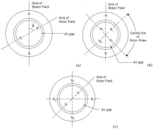
other part. Torque is produced by the interaction of the two magnetic fields. Figure 1(a) shows the
simplified construction of a two-pole machine, in which the north and south poles of the rotor are
attracted by south and north poles (and repelled by north and south poles, respectively) of the stator,
resulting in a torque in the counter-clockwise direction. The magnitude of the torque is proportional to the product of the field strengths of the two fields. The angle δ between the axes of the two fields is known as torque or power angle. For sinusoidal variation of flux in the air gap, i.e. flux density varying sinusoidally with distance around the gap periphery, the torque is also proportional to sin δ. However, if the number of poles on rotor and stator are different, as shown in Figure 1(b) (machine
with 4 poles in the rotor and 2 poles in the stator) the net torque is always zero with respect to the axis
of the stator field. On the N1N2 axis, the pole N1 is repelled by pole N and attracted by pole S
Magnetic Gearing Electromagnetic Concepts
C. G. C. Neves, A. F. F. Filho
Curso de Engenharia de Energia/Universidade Federal do Pampa – Bagé – Brazil [email protected]
Dep. Eng. Elétrica/DELET - Universidade Federal do Rio Grande do Sul - Porto Alegre, Brazil
producing a counter-clockwise torque on the rotor. The pole N2 is repelled by N pole and attracted by
S pole producing an equal clockwise torque. Hence, the net torque is zero. A similar situation takes
place on S1S2 axis. Therefore, no net electromagnetic torque is produced. If the machine has 2 poles
in the rotor and 4 poles in the stator, as in Fig. 1(c), the same occurs. Whenever the number of poles
on rotor and stator are different, net torque is always zero.
(a) (b)
(c)
Fig. 1. Interaction of stator and rotor magnetic fields: (a) 2 poles in the rotor and 2 poles in the stator. (b) 4 poles in the rotor and 2 poles in the stator. (c) 2 poles in the rotor and 4 poles in the stator.
The conclusion is that all rotating machines (generators and motors) must have the same number of poles on
the stator and rotor for steady unidirectional torque.
III. MODULATION PHENOMENA OPERATING PRINCIPLE
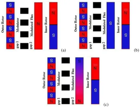
The operating principle of the flux-modulation can be explained with the help of Fig. 2, which is a simplified picture of the outer rotor composed with PMs polarized north and poles interacting with the
static modulators (ferromagnetic pole pieces) [2]. The left hand side of each picture represents the PMs
on the outer rotor. The middle black pieces represent the ferromagnetic flux modulator and the right -hand side represents the flux content produced by modulation that the inner rotor would interact with. This means the flux at left hand side is created by the outer PMs while the flux at right hand side is
created by modulation. In Fig. 2(a) the modulation pieces will only produce flux from north poles,
because they face only north poles, resulting in a north pole. In Fig 2(b) the modulation pieces will
only produce flux from south poles, because the modulation pieces are moved just by one space and the
pairs of north and south poles will oppose each other, and only the end ones will produce flux creating
one north and one south at the ends that would interact with the inner rotor. The relative position
between the outer rotor PMs and modulators controls how the two rotors interact with each other.
(a) (b)
(c)
Fig.2. Power Interaction of outer rotor PMs and modulators: (a) Only a north pole. (b) Only a south pole. (c) A north-south pair which will interact with the inner rotor north-south pair.
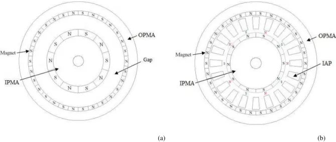
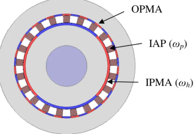
IV. MAGNETIC GEARED MACHINES CONSTRUCTION A Magnetic Gear consists of following components as shown in Fig. 3(a):
1. Outer permanent-magnet array (OPMA) with a pole-number (pl). 2. Inner permanent-magnet array (IPMA) with a number of pole-pairs (ph).
3. Intermediate annular pole-pieces (IAP) composed of Ferro-magnetic modulators (np).
Fig. 3. Construction of a Magnetic Gear.
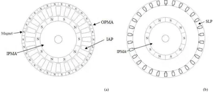
And the Magnetic Geared Generator consists of the same components of the magnetic gear with the
addition of a stator juxtaposed to OPMA, comprising a slotted lamination pack (SLP) as shown in Fig.
Fig. 4. Construction of Magnetic Geared Generator.
V. CO-AXIALMAGNETICGEARWORKINGPRINCIPLE
If the reasoning applied on the section II is used in a cylindrical rotating structure, one can notice
that the situation shown at Fig. 2(c) can be reproduced. Figure 3(a) shows a cylindrical magnetic
structure composed of two rotors separated by an air-gap, the outer rotor and the inner rotor with
different number of poles. Since the numbers of poles are different, it is not possible to produce
torque.However, if the ferromagnetic pole pieces (modulators) are puttedbetween the outer rotor and
the inner rotor, it will alternately “short-circuit” N-S pole-pairs of outer rotor or produce a pole (north
or a south) similar to what occurred at Fig. 2(c). The result of this is a modulated 10 poles flux in the
inner air-gap, represented by the red North’s and blue South’s, shown on Fig. 4(b) since the inner
rotor has 10 poles the net torque will be different than zero and constant as explained in the first
section of this paper.
(a) (b)
VI. MAGNETICGEAREDGENERATORWORKINGPRINCIPLE
The principle of operation of the magnetic geared generator can be understood by considering the operation of the different sub-components within it; that is, the magnetic gear and the electrical machine. Fig. 5(a) shows the elements which contribute to its magnetic gearing action: the IPMA, IAP and OPMA. Fig. 5(b) shows the elements which contribute to its working as an electrical machine: the SLP with the copper windings and the IAP.
(a) (b)
Fig. 5. (a) Magnetic gear components. (b) Convectional PM generator components.
The high-speed inner rotor or IPMA contributes to the operation of both the electrical machine and
the magnet gear. This rotor interconnects the magnetic gear with the electrical machine and so the
mechanical torque is not applied to the IPMA, but on IAP which is the input shaft. The mechanical
torque applied to the IPMA by the magnetic gear is smaller than that applied to the IAP due to the
gearing effect. Consequently, the electromagnetic torque produced by the stator could be only a
fraction of the total input torque. Thus the required magneto-motive force (MMF) in the machine, and
hence the copper losses, are significantly smaller than in a conventional direct-drive generator, which
would have to react the full torque on the input shaft [3]. Consequently the geared machine uses less
active material than would be used by a combination of a magnetic gear and separate electrical
machine.
VII. MAGNETICGEARAIRGAPFLUXDISTRIBUTION
Flux harmonics are essential for the operation of a geared machine then they will be discussed in
detail in this section. The flux distribution in the outer air gap as function of time will be
mathematically expressed and studied when the OPMA is removed and only the IPMA and IAP
remain. The respective rotation velocities of the IPMA and IAP are given as h and p for the
Fig. 6. Simplified view of the coaxial magnetic gear.
The magneto motive force (MMF) of the IPMA and the permeance of the IAP are mathematically
expressed by (1) and (2), respectively
sin
2h 1
p t
h A
F h h
h
ri
1(2 -1)
(1)
P B sin
2 1
n
t
Pr
pp 1 0 1) -(2 (2)
where A is the permanent magnet MMF amplitude,B is the modulators permeance amplitude and
0
P is the permeance of vacuum.
The product of (1) and (2) yields the outer air gap flux distribution:
sin
C t
h AP h 1 h 0
o
1(2 -1)
1 h p 11 2 h 1 p 2 1 2 1 2 h 1 p 2 1 2 0 t C C C C C C cos t C C C C C C cos C 2 1 (3)
where 0
,C1
2h 1
ph 1 p 2 1 h 2 ABC
and C2
2p1
np .From (3), it can be seen that flux distribution consists of three main components: one fundamental
component and two harmonic componentsC2C1. The fundamental component (FC) depends only
ofFri
, given by Eq. (1) which depends of spatial harmonic number C1 and of rotation speedh,that are exactly the same speed of Fri
. The other two harmonic components (called H1 and H2)exist due to the permeance of the IAP pole-pieces which modulates Fri
. Also, from (3) it can beseen that the angular velocities of H1 and H2 are different from that of the MMF. This means that
when the IPMA is rotated, the fundamental (FC) follows the IPMA, but H1 and H2 do not follow it.
This is the main point of the operating principle of a magnetic gear. Either H1 or H2 can be chosen to
create a magnetic gear or the magnet gearing effect, but usually H1 is chosen due to its higher flux
density. Figure 7(a) shows the computed flux distribution in the outer air gap at t= 0 sec using FEM
and its harmonic analysis is shown in Fig. 7(b).
IAP (
ω
p)
OPMA
(a) (b)
Fig. 7. (a) Radial field density at outer air-gap due to the inner magnets only, with modulating rotor. (b)Radial field density harmonic content at outer air-gap due to the inner magnets only, with modulating rotor.
The dominant components are 2nd, 19th, and 23th, which each corresponds to FC, H1 and H2, respectively, since ph= 2 and np= 21, when hp1 in Eq. 3. Since H1 has much higher flux density than H2, pl must be equal to 19 (np ph 19). Taking this as general rule the following
generic poles relation is adopted:
p l
h p n
p (4)
VIII. MAGNETICGEAREDMACHINESGEARRELATIONS
If each term of (4) is multiplied by its respective speed, it gets the following expression:
p p l l h
h p n
p
(5)Where, h is speed of inner rotor, l is speed of the outer rotor and p is the speed of modulator.
When one of the three parts of the gear is stationary, there will be a constant relation or gear ratio
) G
( r between the speeds of other two parts. For example when the modulators are stationary
) 0
(p the machine works as mechanical gear,Gr is equal to 9.5 since pl 19 and ph 2:
h l r p p G -l h (6)
Therefore, the relation between the speeds is inversely proportional to the ratio between the
numbers of pole-pairs, and rotors run in opposite directions. If it is considered there are no losses, the
power in inner rotor is equal to power in outer rotor, then:
r l h h l l h G 1 p p T
T
(7)
Therefore, the ratio between the torques is directly proportional to ratio between the numbers of
pole-pairs. Alternatively, when the OPMA is held stationary(l0), and the IAP is driven by a
turbine the machine works as magnetic geared generator, the gear ratio becomes:
h r
p np
G
p h
Therefore, the relation between the speeds is inversely proportional to the ratio between the
numbers of modulators and numbers of pole-pairs of IPMA, and both rotors run in the same direction.
If it is considered there are no losses, the power in inner rotor is equal to power in the modulators,
then:
r h p h
h p
G p np T
T
(9)
As both shafts are now rotating in the same direction, a higher gear ratio of 10.5 is obtained since
21
np and ph 2
.
IX. MAGNETICGEAREDGENERATORSIMULATIONANDANALYSIS
If slots are stamped in the stator of the magnetic gear and they are wounded in a certain way the
magnetic gear became a magnetic geared generator as shown on Fig. 8 (a). In the geared generator
model consideredph, pl and np are equal to magnetic gear analyzed in the last section, then the 19
th
(H1) is used to create the gearing effect. However, a harmonic flux component of air gap must couple
with the stator winding to electromotive-motive-forces (EMFs) be induced in the winding phases.
This is done by ensuring that the number of generator winding pole pairs is the same as the IPMA
array pole pair, then in the operation as this magnetic geared generator the 2nd flux component couples with the generator coils to produce power as shown in Fig. 8 (a). In order to increase the 2th harmonic component and increase the EMFs, in this model, there are 6 generator coils and they are wound as
show in Fig. 8 (b).
(a) (b)
Fig. 8. (a) Simplified view of the Magnetic Geared Generator. (b) Magnetic Geared Generator winding connections.
A. Stator Winding Flux Analysis
In order to calculate only the flux generated by stator winding the OPMA and IPMA were removed,
and the flux distribution of the air gap inside of the stator when only the generator coils were excited
was determined by FEM static analysis. Figure 9(a) shows the resulting waveform and Fig. 9(b) the
harmonic. Therefore it can be confirmed that the generator coils will be able to be excited by the
IPMA permanent magnets and EMFs will induced in the stator winding phases.
(a) (b)
Fig. 9. (a) Flux density of Stator. (a) Waveform (b) Harmonic Spectrum
B. Electromagnetic Torque Modelling
Electromagnetic torque is produced in a magnetic geared machine when the energy stored in
magnetic fields varies with rotation of the components. Torque on a component can be expressed as:
c ' W T (10)
where is W'the co-energy of the system and is the c angular position of the component on which
the torque is calculated. In this analysis it is assumed that all the co-energy is stored in the air-gaps
and the magnets. In these regions, the co-energy can be calculated as
V 2
0
' B dV
2 1 W
(11)
whereB is the air-gap flux density and assuming that the permeability of the magnets is
approximately equal to that of air (free space).
The movement is taking into account by Movement Band Technique [9] and the Coulomb’s virtual
work method [11] was used for torque calculation in the moving band:
mb e N 1 e 2 0 d B 2 1 L T G G G GBT -1 (12)
where B=[Bx,By], B= B , G the Jacobian matrix of the global nodal coordinates with respect to local element coordinates, and [G] the determinant of G.
The static torque on inner gap is obtained holding the OPMA and IAP still and incrementally
rotating the IPMA step by step (rotating at 1 degree/sec) through the movement band shown in Fig.
10(a). The magnetic torque on outer gap is obtained in the same way but the movement band assumes
the position shown in Fig. 10(b). The torque on IAP is equal to difference between the torque
(a) (b)
Fig. 10. (a) Band to calculate torque at inner gap (rotates at 1 degree/sec). (b) Band to calculate torque at outer gap (rotates at 1 degree/sec).
Figure 11(a) shows the torque on the three regions. It can be found that the torque-angle curves vary
sinusoidally, in which the maximum torque values denote the pull-out torques. On the IAP and inner
gap, the pull-out torques is 475.88 Nm and 44.88 Nm, respectively. Their ratio is 10.6, which has a
good agreement with the ratio np ph that is equal to10.5.
(a) (b)
Fig. 11. (a) Static torque waveforms. (b) Static torque harmonic spectrum at inner air-gap (output torque).
C Cogging Torque Analysis
The cogging torque manifests itself as torque ripple harmonics on the inner air gap (output rotor)
due to interactions between the IPMA and the IAP, when windings currents are null.For the inner
rotor the fundamental cogging torque harmonics equal to 84 pole-pairs, this means, the smallest
spectrum shown at Fig. 11(b) complements this reasoning since the value of the 84th harmonic is only 2% of the fundamental (2th). Hence, the cogging torque is inherently small.
D No-load EMF
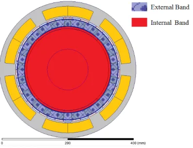
In order to simulate the movement of both rotors in relation to the winding and modulators and
obtain no-load EMF two movement bands are applied as shown on Fig. 12. The external band, placed
in the IAP (input rotor), rotates at 150 rpm and the internal band, placed in the inner air-gap (out
rotor) at 1575 rpm, since the speeds relation is 10.5. As already explained at section VIII both bands
must run in the same direction.
Fig. 12 Bands to calculate EMFs (inner band rotates at 1575 rpm and outer band rotates at 150 rpm).Both bands must run in the same direction
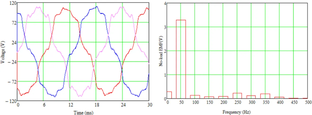
Figure 13 shows the 3-phase EMFs induced when the OPMA is held stationary(l0), the stator
winding is open, and the IAP rotates at 150 rpm simulating the speed transmitted by the shaft of a
wind turbine. The waveform is non-sinusoidal due to the large odd harmonic (3rd, 5th and 7th) as can be seen at harmonic spectrum shown at Fig. 13(b). One can infer that this harmonics are due to the
generators’ winding configuration since the harmonic spectrum of waveform produced only by the
Fig. 13 No-load EMFs (a) Voltage waveforms. (b) Frequency Harmonic Spectrum. X. CONCLUSION
In this paper the magnetic geared machines electromagnetic concepts are introduced. The magnetic
gear modulation mechanism which makes possible rotors of different polarities produce unidirectional
torque was explained in a simple way. The magnetic geared generator working principle was
explained. The poles and speed relations of the magnetic geared machines are obtained and explained
through the use analytical expressions and plots obtained by finite elements method. The gear
relations for magnetic gears and magnetic geared generators are demonstrated mathematically. The
geared generator simulated presents low cogging torque but no-load EMFs generated are deformed by
odd harmonics generated by the stator winding.
REFERENCES
[1] Umans, S. Fitzgerald and Kingsley’s Electric Machinery, McGraw-Hill, 2013.
[2] Brönn, L. Design and Performance Evaluation of a Magnetically Geared Axial-Flux Permanent Magnet Generator. Thesis: MScEng (EE),2012.
[3] Chau, K. T., “A Novel Coaxial Magnetic Gear Using Bulk HTS for Industrial Applications,” IEEE Trans. Appl. Supercond., vol. 20, no. 3, pp. 981–984, Jun. 2010.
[4] Jian, L., K.T. Chau, "Analytical calculation of magnetic field distribution in coaxial magnetic gears", Progress In Electromagnetics Research, Vol. 92, pp. 1-16, 2009.
[5] Atallah, K. and D. Howe, “A novel high-performance magnetic gear," IEEE Transactions on Magnetics, Vol. 37, No. 4, pp. 2844-2846, 2001.
[6] Lian, L; Chau, K.-T; Gong, Y; Jiang, JZ; Yu, C; Li, W, ”Comparison of coaxial magnetic gears with different topologies”, IEEE Transactions On Magnetics, , Vol. 45, n. 10, p. 4526-4529, 2009
[7] Atallah, K., S. D. Calverley, and D. Howe, “Design, analysis and realization of a high-performance magnetic gear," IEE Proc. Electr. Power Appl., Vol. 151, No. 2, pp. 135-143, 2004.
[8] X. Li, K.-T. Chau, M. Chengand, W. Hua, “Comparison of magnet-geared permanent-magnet machines,” Progress In Electromagnetics Research, Vol. 133, No. 3, pp. 177-198,2013
[9] B. Davat, Z. Ren and M. Lajoie-Mazenc, “The movement in field modeling,” IEEE Trans. Magn., vol. 21, no. 6, pp. 2296–2298, November 1985.
[10] B. Silwal, P. Rasilo, L. Perkkio, A. Hannukainen, T. Eirola and A. Arkkio, “Evaluation and Comparison of different numerical computation methods for the electromagnetic torque in electrical machines,” in Proc. Int. Conf. Electrical Machines and Systems, Oct 2013, pp.837–842.
[11] J. Coulomb and G. Meunier, “Finite element implementation of virtual work principle for magnetic or electric force and torque