DOI: http://dx.doi.org/10.1590/1980-5373-MR-2016-1004
Resistance to Pitting Corrosion in Steels Based on the Fe-Cr-Ni-C System
Mérilin Cristina dos Santos Fernandesa; Sandra Nakamatsub; Ana Laura Polississo Ruedaa, Jordan Junqueira Souzaa, Stephania Capellari De Rezendea, Lucíola Lucena de Souzaa,
Neide Aparecida Marianoa*
Received: December 12, 2016; Revised: March 05, 2017; Accepted: April 21, 2017
This study aimed to investigate the efects of diference in nickel content and the tempering
temperatures on the corrosion resistance in 13Cr2Ni0.1C and 13Cr1Ni0.15C steels. Results showed
that passive ilm in 13Cr2Ni0.1C steel is formed more quickly at the lowest and highest tempering
temperature (650°C and 750°C) but the lowest tempering temperature (650°C) showed better resistance
to corrosion pitting. There was passive ilm formation and pitting corrosion in all tempering temperatures of the 13Cr1Ni0.15C steel and changes in tempering temperature does not signiicantly alter polarization
curves, showing similar behavior to steel 13Cr2Ni0.1C tempered at 650°C.
Keywords: Heat treatment, Corrosion, Martensitic stainless steel, Pitting, FeCrNiC
* e-mail: [email protected]
1. Introduction
The study of corrosion marine environments is particularly interesting for low carbon martensitic stainless steels because of the wide use of these steels in equipment
applied in the petrochemical industry and oil production
in ofshore platforms1-3. Localized pitting corrosion is the
most common type of corrosion and diicult to control in
marine environment, especially in deep waters, which are
characterized by high concentration of chlorides, low O2
concentration, presence of corrosive gases - such as CO2 and
H2S - microorganisms and other dissolved salts4.
The superior corrosion properties of stainless steels result from the formation of a thin oxide ilm on surface, called as the passive ilm5. Pitting corrosion occurs when the passive
ilm breaks down in the presence of aggressive ions, such as
chloride ions, resulting in the local dissolution and cavities on
the metal surface6,7. Once the pites is formed, it can initiate
and propagate a crack along the material thickness and lead to a catastrophic failure8.
The stability of the passive ilm has a direct impact on
pitting resistance4, the microstructural characteristics of the
alloy alter the properties of the passive ilm and the pitting resistance, representing a feature of particular interest9. Thus,
the microstructural changes caused by certain heat treatments
applied to stainless steels can result in the formation of surface ilms that exhibit diferent protection capabilities
to resist to pitting corrosion.
Martensitic stainless steels are always quenched at temperatures 200°C higher than inal temperature of austenite formation and tempered near the initial temperature of austenite formation10. At diferent tempering temperatures, the
precipitates or carbides of the tempered martensitic stainless steels are diferent and result in signiicant property changes
since the pits tend to occur near inclusion and precipitated phases11-13. Rodrigues et al observed a typical microstructure of
a martensitic matrix in a supermartensitic stainless steels and ind small precipitates (40 nm)14. In this way, it is necessary
to use a temperature range for heat treatment.
The inluence of tempering temperature on the corrosion resistance of low carbon martensitic stainless steels in
marine environments is still poorly understood, even though
the importance of these steels and the microstructural transformations observed after heat treatments are widely
studied15-18. Thus, this study aimed to investigate the efect
of the tempering temperature on the corrosion resistance of
13Cr2Ni0.1C and 13Cr1Ni0.15C steels.
2. Materials and Methods
The steels were produced in an electric arc furnace with argon-oxygen decarburization (AOD). The chemical
compositions obtained by inductively coupled
plasma-atomic emission spectrometer (ICP/AES), for these steels
are shown in Table 1.
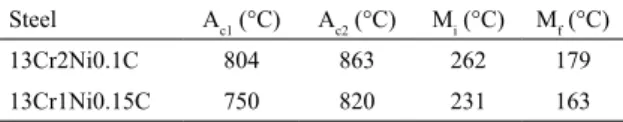
The austenitic transformation temperatures (Ac1 and Ac3) and
martensitic transformation temperatures (Mi and Mf) obtained
by dilatometry by Mendonça et. al19 are shown in Table 2. a Universidade Federal de Alfenas - UNIFAL, Campus Avançado de Poços de Caldas, Rod. José Aurélio
Vilela, BR 267-Km 533, Cidade Universitária, Poços de Caldas, 377015-400, MG, Brazil
b Instituto de Física e Química, Universidade Federal de Itajubá - UNIFEI, Avenida BPS, 1303, Itajubá,
Table 1. Chemical compositions of the steels (wt.%).
Steel %C %Si %Mn %Cr %Ni %Mo
13Cr2Ni0.1C 0.09 0.92 0.75 13.00 2.05 0.15
13Cr1Ni0.15C 0.15 1.02 0.75 13.00 1.03 0.08
Table 2. Temperatures of the steels transformations.
Steel Ac1 (°C) Ac2 (°C) Mi (°C) Mf (°C)
13Cr2Ni0.1C 804 863 262 179
13Cr1Ni0.15C 750 820 231 163
By means of Ac3 values was selected the quenching
temperature of 1000°C for two hours with subsequent tempering for the two steels. Similarly, with Ac1 it was possible to propose
a temperature range for the tempering treatment also for two
hours. Thus, the tempering temperatures used were 650°C,
700°C and 750°C, for 13Cr2Ni0.1C steel and 600°C, 650°C, 700°C and 750°C for 13Cr1Ni0.15C steel. These samples were cooled in air. Heat treatments were performed in a mule furnace without protective atmosphere and temperatures were
monitored by using Chromel-Alumel thermocouple. Corrosion behavior was evaluated by cyclic potentiodynamic
polarization method using a potentiostat Metrohm model
Autolab/PGSTART302 connected to a typical electrochemical cell with a saturated calomel electrode (SCE) used as a
reference electrode, a platinum plate employed as counter-electrode and the working counter-electrode made from the steels studied. Electrochemical measurements were performed in triplicate for each condition. An aerated solution of synthetic marine medium with a concentration of 60,000 ppm at room
temperature Cl, prepared according to ASTM D1141-98,
was used. After immersion in the solution, the samples were subjected to conditions of open circuit potential (OCP). The
potentiodynamic curves were measured at a potential scan
rate of 1 mV/s with direction reversal when impacted the anodic current density of 10-3 A/cm2.
Figure 1. Curves obtained in the corrosion test in synthetic marine environment to 60,000 ppm Cl- of the
13Cr2Ni0.1C steel. (a) OCP and (b) CPP.
Table 3. Electrochemical parameters of the 13Cr2Ni0.1C steel.
Tempering Temperature Ecorr (V) Epit (V) Ipp (A/cm2) E
prot (V)
650°C -0.439 -0.188 5.12E-6 -0.438
700°C -0.767 -0.292 6.55E-6 -0.434
750°C -0.527 -0.240 5.42E-6 -0.431
Microstructural characterization was carried out using optical microscopy. The surface etching was achieved with modiied Behara at room temperature, in accordance with
ASTM E3-11.
3. Results and Discussion
The open circuit potential (OCP) and cyclic potentiodynamic polarization (PPC) curves obtained for 13Cr2Ni0.1C steel are
shown in Figure 1 while the electrochemical parameters are presented in Table 3.
The OCP curve towards more positive potentials suggests formation of a passive ilm on the metal surface, while the reduction of potential suggests generalized corrosion. Figure 1a shows that in the tempering temperatures of 650°C and 700°C the OCP curves move towards more negative potentials with increasing time, but for the sample tempered at 750°C the OCP curve stabilized at less negative potentials indicating formation of the passive ilm. Figure 1b shows that the passivation region
is noticeable in all curves but the sample tempered at 650°C shows a less clear passivation region.
In Table 3 it is possible seeing a signiicant diference
between the corrosion potential (Ecorr), pitting potential (Epit) and current passivation (Ipp) values at each tempering
temperature, but the values are very close in case of the
protection potential (Eprot). More negatives values of pitting potential lead to lower resistance to pitting corrosion. Thus, the sample tempered at 650°C shows the highest resistance to pitting corrosion.
Figure 2 shows the micrograph by optical microscopy of the 13Cr2Ni0.1C steel tempered. The black arrows indicate the martensitic matrix and white arrows indicate the delta ferrite phase undissolved derived from gross melting. It is possible to identify grain boundaries illed with the martensitic phase
In the micrograph of the sample tempered at 700°C is possible to observe large ferrite delta islands, this leads to a decrease of pitting corrosion potential (Epit = -0.292 V),
because delta ferrite presence produces detrimental efects
on corrosion resistance20. In the case of sample tempered at
750°C ferrite delta phase is more dissolved and consequently
the pitting potential increases (Epit = -0.240 V) while in the
sample tempered at 650°C it is highest (Epit = -0.188 V) due to
reinement of the martensitic laths (needles-like structures) in
the sample tempered at 750°C that lead to create more active
sites facilitating pitting corrosion.
The open circuit potential (OCP) and cyclic potentiodynamic polarization (PPC) curves obtained for 13Cr1Ni0.15C steel
are shown in Figure 3 while the electrochemical parameters are presented in Table 4.
Figure 2. Micrograph by optical microscopy of the 13Cr2Ni0.1C steel tempered at (a) 650°C, (b) 700°C and (c) 750°C.
Figure 3. Curves obtained in the corrosion test in synthetic marine environment to 60,000 ppm Cl- of the
13Cr1Ni0.15C steel. (a) OCP and (b) CPP.
Table 4. Electrochemical parameters of the 13Cr1Ni0.15C steel.
Tempering Temperature Ecorr (V) Epit (V) Ipp (A/cm
2) Eprot (V)
600°C -0.461 -0.161 5.00E-6 -0.449
650°C -0.455 -0.179 4.21E-6 -0.330
700°C -0.419 -0.139 3.80E-6 -0.309
750°C -0.420 -0.140 4.15E-6 -0.331
Figure 4. Micrograph by optical microscopy of the 13Cr1Ni0.15C steel tempered at (a) 650°C
In Figure 3a it is possible seeing that all OCP curves show the tendency to stabilize in potentials with more positive values, indicating the formation of the passive ilm in all samples.
Furthermore, it notes the curves show the same positive
hysteresis tendency indicating the occurrence of localized pitting corrosion. Another feature present in Figure 3a is a passive region, which for some samples is not a straight line because occurred a slow oxidation. The polarization curves in Figure 3b showed no signiicant diference in their positions, which conirmed the formation of passive ilm and pitting localized corrosion in all tempering temperatures.
According to Table 4 the values of the electrochemical parameters found for the samples with diferent tempering temperatures were very close, so that the variation of the tempering temperature was not signiicant in the corrosion characteristics of this steel corrosion characteristics. From the micrographs of the 13Cr1Ni0.15C steel shown in Figure 4, it is observed that with increasing of the tempering temperature the martensitic matrix becomes more reined and orderly, but the delta ferrite does not have a preferred site.
Comparing the electrochemical parameters of the two
steels, it is possible to notice that 13Cr2Ni0.1C steel has the
most favorable value at tempering temperature of 650°C while all values found for the electrochemical parameters of 13Cr1Ni0.15C steel are close to the best value found to the irst steel.
4. Conclusions
The tempering temperature used in 13Cr2Ni0.1C
steel inluences in the electrochemical parameters. In the temperature of 650°C and 750°C the passive ilm is formed more quickly and in the tempering temperature at 650°C has a better corrosion resistance performance. In 13Cr1Ni0.15C steel the curves OCP and PPC obtained in the corrosion tests indicated passive ilm formation and occurrence of localized
pitting corrosion in all tempering temperature used, in order
that the tempering temperature was not signiicant in steel
corrosion characteristics. The electrochemical parameters
of the latter steel showed values close to those found in the temperature of 650°C of the irst steel.
5. Acknowledgements
The authors acknowledge to FAPEMIG, CNPq, CAPES
and FAPESP.
6. References
1. Turnbull A, Griiths A. Review: Corrosion and cracking of weldable 13 wt-%Cr martensitic stainless steels for application in the oil
and gas industry. Corrosion Engineering Science Technology. 2003;38(1):21-50.
2. Yin ZF, Wang XZ, Liu L, Wu JQ, Zhang YQ. Characterization of corrosion product layers from CO2 corrosion of 13Cr stainless steel in simulated oil ield solution. Journal of Materials
Engineering and Performance. 2010;20(7):1330-1335.
3. Ma XP, Wang LJ, Liu CM, Subramanian SV. Microstructure and properties of 13Cr5Ni1Mo0.025Nb0.09V0.06N super
martensitic stainless steel. Materials Science and Engineering: A. 2012;539:271-279.
4. Anselmo N, May JE, Mariano NA, Nascente PAP, Kuri SE.
Corrosion behavior of supermartensitic stainless steel in aerated and CO2-saturated synthetic seawater. Materials Science and
Engineering: A. 2006;428(1-2):73-79.
5. Mu LJ, Zhao WZ. Investigation on carbon dioxide corrosion behaviour of 13Cr stainless steel in simulated stratum water.
Corrosion Science. 2010;52(1):82-89.
6. Park JO, Matsch S, Böhni H. Efect of Temperature and
Chloride Concentration on Pit Initiation and Early Pit Growth Stainless Steel. Journal of the Electrochemical Society. 2002;149(2):B34-B39.
7. Marcelin S, Pébère N, Régnier S. Electrochemical characterisation
of a martensitic stainless steel in a neutral chloride solution.
Electrochimica Acta. 2013;87:32-40.
8. Caines S, Khan F, Shirokof J. Analysis of pitting corrosion on
steel under insulation in marine environments. Journal of Loss
Prevention in the Process Industries. 2013;26(6):1466-1483.
9. Gervasi CA, Méndez CM, Bilmes PD, Llorente CL. Analysis of the impact of alloy microstructural properties on passive ilms formed on low-C 13CrNiMo martensitic stainless steels.
Materials Chemistry and Physics. 2011;126(1-2):178-182.
10. Song Y, Li X, Rong L, Yiyi L. Anomalous phase transformation from martensite to austenite in Fe-13%Cr-4%Ni-Mo martensitic
stainless steel. Journal of Materials Science & Technology. 2010;26(9):823-826.
11. Lu SY, Yao KF, Chen YB, Wang MH, Liu X, Ge X. The
efect of tempering temperature on the microstructure and electrochemical properties of a 13 wt.% Cr-type martensitic
stainless steel. Electrochimica Acta. 2015;165:45-55.
12. Seifert M, Wieskämper D, Tonfeld T, Huth S. Corrosion properties of a complex multi-phase martensitic stainless
steel depending on the tempering temperature. Materials
and Corrosion. 2015;66(11):1290-1298.
13. Ryan MP, Williams DE, Chater RJ, Hutton BM, Mcphail DS. Why stainless steel corrodes. Nature. 2002;415:770-774.
14. Rodrigues C, Lorenzo P, Sokolowski A, Barbosa C, Rollo J. Development of a Supermartensitic Stainless Steel Microalloyed with Niobium. Journal of ASTM International. 2006;3(5):1-5.
15. Bilmes PD, Solari M, Liorente CL. Characteristics and efects of austenite resulting from tempering of 13Cr-NiMo martensitic steel
weld metals. Materials Characterization. 2001;46(4):285-296.
16. Calliari I, Zanesco M, Dabalà M, Brunelli K, Ramous E. Investigation
of microstructure and properties of a Ni-Mo martensitic stainless
17. Wang P, Lu PS, Xiao NM, Li DZ, Li YY. Efect of delta ferrite on impact properties of low carbon 13Cr-4Ni martensitic stainless steel.
Materials Science and Engineering: A. 2010;527(13-14):3210-3216.
18. Lei X, Feng Y, Zhang J, Fu A, Yin C, Macdonald DD. Impact of Reversed Austenite on the Pitting Corrosion Behavior of Super 13Cr
Martensitic Stainless Steel. Electrochimica Acta. 2016;191:640-650.
19. Mendonça R, Cronemberger MER, Santos MT, Mariano NA.
The efect of the tempering in martensitic stainless steels:
13Cr4Ni0.02C, 13Cr2Ni0.1C E 13Cr1Ni0.15C. Proceedings
of the 68th ABM International Annual Congress; 2013 Jul
30-Ago 2; Belo Horizonte, MG, Brazil. São Paulo: ABM; 2013.
p. 4203-4209.
20. Kim SH, Moon HK, Kang T, Lee CS. Dissolution kinetics of delta ferrite in AISI 304 stainless steel produced by strip