ISSN 1549-3636
© 2006 Science Publications
Corresponding Author : Babahenini Mohamed Chaouki, IRIT, équipe SIRV, Université Paul Sabatier, 118 Route de Narbonne, F-31062 Toulouse Cedex 9, France
Integration of Voxel Colouring Technique in the Volumetric Textures Representation
Based on Image Layers
1
Babahenini Mohamed Chaouki,
2Hemidi Djallel,
2Djedi Noureddine
1
Institut de Recherche en Informatique de Toulouse. Equipe SIRV. Université Paul Sabatier. Toulouse
France
2
Department of Computer Science, Mohamed Khider University, Biskra, Algeria
Abstract: This paper presents a method for integrating a technique of reconstruction scene (voxel colouring) starting from images of the reference element of a volumetric texture, this one will be converted in a second phase into a whole of layers (2D images considered as transparent textures), which will be projected and composed successively on surface defined as volumetric grid using the Z-buffer algorithm. The model suggested allows primarily made realistic of repetitive complex scenes lower cost of calculation due to the effective exploitation of the capacities of the graphics boards and to the fact that it takes account of the level of detail according to the distance of the observer and the vision angle, in the representation of the reference element.
Key words: Real time, Image layers, Level of details, Textures volumetric, Voxel coloring
INTRODUCTION
Volumetric textures offer realistic rendering of the repetitive complex scenes, in acceptable times (from 5 to 20 minutes) by using the ray casting. However, for applications requiring the real time, obtaining an additional profit appears not easily possible by preserving this technique in its initial form (representation of the reference volume by an octal tree). Among the approaches of image based rendering, dealing with the problems of geometrical and temporal complexity, exist the rendering based on images layers. This technique allows realistic rendering of scenes and objects in lower calculation cost than with a traditional method. This benefit of calculation time is due to the exploitation of capacities of the graphics boards treating, effectively, the polygons. So each layer of image must be represented by a textured polygon.
For rendering, it is enough to project and successively compose the layers on the image plan (Z-Buffer) and to obtain, thus, the final image. Each projected layer is combined with the preceding result by taking account of the density of each pixel.
The projection of a layer is faster than calculations of projection for each voxel along a ray, which allows an appreciable benefit of time.
This paper present a method for integrating the technique of colouring voxel in volumetric textures containing layers of images[1], which will make it possible to generalize the reference volume which will be initially definite from images key (real photographs or synthesized images), transform it into a whole of
layers and to adopt the method of Meyer[2] to carry out one made real time by exploiting the graphics boards capacities.
Previous work:
Initial representation: In 1989 Kajiya and Kay[3] presented the volumetric textures technique applied to fur rendering, which constitutes an efficient way of representing and rendering complex repetitive data. The principle consists in making a sample of volumetric texture; which is stored in a volume of reference, whose deformed copies, called “texels”, will be mapped on a surface made up of bilinear patches.
The reference volume represents area of space sampled onto voxels. Each voxel contains information space of presence (density) and function indicating the local photometric behaviour, which consists of a local orientation and an analytical function of reflectance. The volume of reference is then plated in a repetitive way on all surface as for a traditional surface texture, it is then deformed in order to ensure continuity between the close texels.
The rendering is done by volumetric ray tracing when a texel is crossed. A stochastic sampling of the ray is carried out in order to reduce calculations; the local illumination is then carried out using the model of reflectance which simulates the presence of a cylinder. A ray is sent towards the source of light in order to test the shade of the current voxel.
carry out an effective representation of the complex geometries by generalizing the preceding method and by introducing the principle of level of detail into the representation of the texel. F. Neyret[4] proposed the use of the octree to store reference volume. Any voxel in the octree simulates the photometric local behaviour of the object represented in the texel, and contains the local density and a micro-primitive modelling the local reflectance.
Volumetric texture rendering is then modified according to the multiscale data structure and to the reflectance. So it is encoding in two passes one made total which is done on the level of each texel by using a traditional algorithm of cone tracer. This algorithm course respectively space scene, space texel then space object and uses a trilinear interpolation and one made local which is done on the level of each voxel by integrating the model of local illumination of Phong.
Representation based on image layers: To minimize the time of rendering, Lacroute and Levoy[5] introduced volumetric rendering by image layers where the volumetric data are interpreted as layers and the voxels are factorized in texture and then treated in parallel. The algorithms rely on a factorization of the viewing transformation that simplifies projection from the volume to the image, which allow constructing an object-order algorithm with the same advantages as an image-order algorithm. They call the factorization the shear-warp factorization. The principal advantage is the benefits of time because the projection of a layer is faster than the calculation of projection for each voxel along a ray. Westermann and Ertl in 1998[6] presented a model including diffuse lighting in the medical images; they used a single texture of NxXxY resolution. For rendering they position and turn correctly the cube in the scene and then determine the polygons forming the intersection of parallel plans to the image plan with the cube in the scene. To simulate the diffuse shading, they introduced another 3D texture whose color information corresponds to the normal in each point of volumetric texture.
To carry out volumetric textures in real time, Meyer and Neyret[2] tried to benefit from the capacity of the graphics hardware to treat textured polygons quickly. In this context, a cubic volume is represented by a series of slices covered with a transparent texture. A 3D object is thus translated into sections. As the slices are not front the observer and do not have a thickness, one is likely to see between them, thus they have defined three directions of slices and used one among it according to the point of view of the user. The generation of the texels can be done in two manners, by converting a polygonal representation or starting from a Perlin texture.
Schaufler[7], introduced a new type of impostor, which has the property to limit the errors of occlusion to
the user specified amount. This impostor is composed of multiple layers of textured meshes, which replace the distant geometry and is much faster to render. It captures in the model the complexity of suitable depth without resorting to a complete of the scene. The layers can be updated dynamically during visualization.
A very interesting adaptation of volumetric textures containing image layers was developed by Lengyel[8], for real time rendering of fur. As a pre-process, he simulates virtual hair with a particle system, and simplifies it into a volume texture. Next, he parameterizes the texture over a surface of arbitrary topology using “lapped textures” which is an approach for applying a texture sample to a surface by repeatedly pasting patches of the texture until the surface is covered. At runtime, the patches of volume textures are rendered as a series of concentric shells of semi-transparent medium. The method generates convincing imagery of fur at interactive rates for models of moderate complexity.
Models containing billboard[9] allow a representation of the objects containing semi-transparent textures, the rendering engine always directs towards the observer. Jakulin[10] proposes a hybrid model between the texels. He uses ordinary mesh-based rendering for the solid parts of a tree, its trunk and limbs, the sparse parts of a tree, its twigs and leaves, are instead represented with a set of slices, an image based representation. For rendering, it blend between the nearest two slicing according to the angle between the viewpoint and the normal with the slice.
With the advent of rising generation of the graphics hardware, Sénégas[11] could develop a new version of volumetric textures in real time by adding a calculation of illumination to the texels. These graphics hardware make possible to evaluate illumination in each pixel of the polygon and either at the tops of the grids. Then these values will be interpolated during the process of rasterisation which consists in filling the 2D polygon pixel by pixel. A layer of a texel is then made up of two section:
1. a section coding color (RGB) and the density (channel alpha).
2. a section coding the normals.
n-tuple of dimension 0 with attributes of form and of texture color which locally approximates the surface of an object. The surfels can be considered as an object with out explicit connectivity with their neighbours, which is in fact a very flexible representation to handle. As a pre-process, an octree-based surfel representation of a geometric object is computed. During sampling, surfel positions and normals are optionally perturbed and different levels of texture colours are prefiltered and stored in every surfel. During rendering, a hierarchical forward warping algorithm projects surfels to a z-buffer. The display cost of an object is proportional to its size with the screen and not to its intrinsic complexity.
The reconstruction of surface can be made either in space image [15], by taking account of transparent semi surfaces (use of an A-buffer), or in space object [16] by using an acceleration by the graphic material. To deal with the problem of the aliasing for the objects having a complex texture, one uses a filter by elliptic average weighting (EWA Filter, '' Elliptical Weighted Average '') which gives very good visual results but have heavy cost in computing times [17]. Various accelerated methods of this filter were presented [18, 19], but their performances are not sufficient.
In 2002 [20], Guannabeau, adopted a technique for visualization of volumetric textures containing surfels where the reference element is represented using a LDC tree.
Motivations: The motivation of our representation is: - Encoding of any kind of shape initially represented
by a series of real photographs or synthesized images using voxel colouring technique in volume pattern.
- Providing multi-scale representation by converting obtained volumes to image layers witch will be projected and decomposed successively on surface support defined as volumetric grid.
- Using capabilities of graphics hardware, witch makes volume rendering interactive.
Integration of voxel coloring technique in the representation of volumetric textures based on images layers:
Modelling of the reference element by the voxel colouring technique: Voxel colouring technique was introduced by Seitz [21], it can considered as a voxel-based 3D reconstruction technique to compute photo realistic volume models from multiple color images V0,…, Vn.
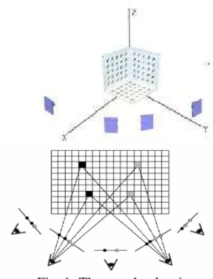
It consists in rebuilding a scene 3D by assigning colors (radiances) to voxels (points) in a 3D volume and by guaranteeing consistent with a whole of basic images (Fig. 1). [21].
Fig. 1: The voxel colouring;
The initial stage of the algorithm consists in breaking up the scene into a set of voxels. For that, we define a subdivision of space 3D in layers of voxels of uniform distance at the camera:
{
V V d}
vd = =
v
dir
i=1 =
ν
Where d1,…, dr is a sequence of increasing numbers and
.
is an occlusion compatible function.Voxel colouring algorithm is presented thus [21]:
φ ← S
For i=1, …, r do //Iterate through the layers
For each V∈
i
d
ν
do//Iterate through the voxels in the layer
For j=0, …, n do
//Project the voxel on each image Compute footprint ρ of V in Ij πj ← { p ∈ρ | p is not marked} End for
Compute λV //Evaluate the voxel consistency
If m>0 et λV<thresh then
S←S∪
{ }
V //color the voxel
i i π π π
1
= ∪ ∪
← //Memorize image pixel to mark
End If End for
Mark the pixel in π End for
To be able to reconstruct the 3D scene, we used a whole of synthesized images, generated by using a modified ray casting. After having computed a whole of images of depth around the objects of the scene, we can rebuild this scene by using these images accompanied by other information such as: the position of the camera, focal angles of vision (vertical and horizontal) and the dimension of each image. The process of reconstruction is an opposite projection of the whole of pixels of each image towards the space scene discretized in voxels. This operation makes it possible to color the transparent voxels and to have thus the same scene, represented this time by a series of voxels. This process (Fig. 2) is carried out in the following way:
• Initially, we construct the grid 3D of the transparent voxels (the value of alpha is 0).
• We use information accompanying the camera to compute the matrix M of change scale between the object space and the camera space. M = RX×RY×T (where: RX and RY are the two matrices of rotation to bring back the vector of vision on OZ axis, and T is the translation bringing back the camera to the centre of the scene.
• Once the direction of the ray obtained, we compute the position of the pixel projected in space scene by using the information of depth accompanying this pixel: P=O+
λ
×D. Where: O is the ray origin,D
is the normalized vector of the ray direction and λ corresponds to the depth of the point. P.• Then we compute the position of the corresponding voxel in the grid and we assign the color of the pixel to the found voxel, and the value alpha of the voxel is 255.
Fig. 2: Reconstruction from the images (the direction of the arrow indicates the direction of projection) (a) Creation of the images (b) Opposite projection of
the pixels.
Once the creation of the reference volume by the technique of voxels colouring made, we can use the whole of voxels coloured for the generation of our volume of reference containing layers. The process of passage between these two representations is illustrated in Fig. 3.
Fig. 3: The passage between a voxel representation and image layers representation.
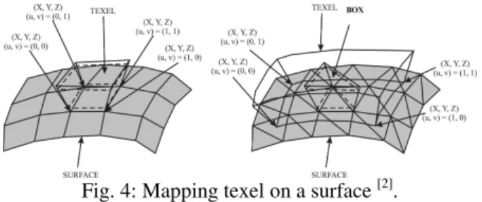
Rendering by using the new model of volumetric texture: The surface can be represented by a whole of boxes built by using a surface grid. Each box is thus defined by 2N points [2]: N points for the base and N points for the top (Fig. 4). To indicate how the box in the texel is located, it is necessary to add to the base points the textures coordinates U, V.
For the creation of a surface grid, we used sinusoidal functions (basic points), which one will be able to be perturbed by textures of Perlin (Perlin noise) in order to create grounds.
Fig. 4: Mapping texel on a surface [2].
The volume of reference is represented by a whole of N 2D images of size X ×Y to format RGBA (Red, Green, Bleu and the Alpha transparency). One can also see it like a volume of N×X×Y voxels having each one four components (three of colors and transparency) [2]. This volume of reference does not contain any more information on reflectance since the precalculated color is stored in the place, which implies that the render of shades and lighting is fixed during its construction.
Rendering of a scene passes by rendering of all the boxes comprising a whole of textured transparent polygons (the images layers). From the information contained in a box, we obtain the coordinates (in space scene X, Y, Z and in space textures U, V) of textured faces which we display with OpenGL [2]. A box is defined by its points of the base and the top. The calculation of the coordinates of the various sections is done by a linear interpolation between a point of the base and a point of the top. The face coordinates i are:
1 0 . 0
1 0 . 0
1 0 . 0
− +
=
− +
=
− +
=
n C C n
i C Ci
n B B n i B Bi
Where A0, B0, C0 are coordinates of bottom layer, An-1, Bn-1, Cn-1 are coordinates of top layer, and n is the number of layers.
The coordinates of the points of these faces are recomputed only when the box becomes deformed. The technique of the Z-buffer imposes that the display of transparent faces is done by order of depth. When OpenGL displays a new polygon, it treats all the pixels of this polygon like this [2]:
If (the depth of the point is further away from the eye than that of the Z-buffer) and (the point of the Z-buffer belongs to a completely opaque polygon) Then
The point is rejected,
else we display it by applying the following formula: Cscreen = Alphapoint × Cpoint +(1 - Alphapoint) × Cscreen
If the point belonged to an opaque semi polygon, it is necessary to make a composition of the colors [2] by displaying the faces of the back forwards by respecting the order of depth according to the point of view.
Fig. 5: Order of the faces display: Case A of 0 with n-1. Case B of n-1 with 0.
The method of rendering all textured surfaces consists in taking each face of surface and displays the box being with the top. The algorithm used is as follows:
For i = all boxes do
For n = all sections box do load texture n
display section n of box i
End for
End for
The loading of a texture (layer) in the associated memory corresponds to change a context (the use of the function glBindTexture to allot an identifier to texture and glTexImage 2D to load texture [22]).
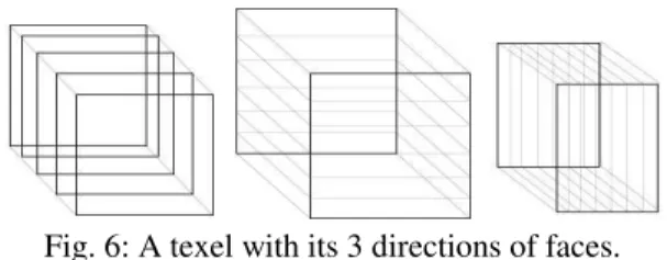
When the angle of sight of the texel is very acute it is seen clearly that surface is a superposition of faces. To solve this problem, we chose to introduce two other directions of alternate sections, to use when the first gives a too degenerated quality. We choose the most adapted direction to the position from the point of view (see an example of swing in case A of Fig. 5 on the right) [2].
Fig. 6: A texel with its 3 directions of faces. To know which direction is the best, one carries out the three scalar products between the axis of sight V and the three directions of the texel NR, T, B (Normal, Tangent, Bi-normal), and one chooses the direction whose scalar product is largest in absolute value.
Introduction of the multi-resolution aspect: The introduction of the multi-resolution aspect consists in reducing the number of display layers while keeping a constant visual quality, the objective being to find right balance between the realism and the computing speed. Thus, we seek to describe the importance of an object in a scene in order to choose the smoothness of his representation.
- When the texel is seen perfectly in the axis or when the point of view deviates a little from the direction of vision, the effect of relief is not important. We could thus display only one limited number of textured faces which would be the precalculated result of “the stacking” of all the textured faces [2]. The idea is to display a variable number of layers which depends on the angle of view, and more precisely of the distance d (see Fig. 7) which corresponds to the visible depth inside the object.
The quality criterion C1 is defined by raising the distance d by d0, which gives:
0 ) tan(
d n
a H
<
× , it is
deduced that n
d a H
< ×
0 )
tan( . Where n is the minimum
number of sections which should be used to keep a quality connect constant.
Fig. 7: The first criterion.
Fig. 8: The second criterion.
- The C2 criterion consists in defining the spacing between two layers of a texel (i.e. we wants that the distance H projected in the screen is limited by d1 (in pixels)). The distance h projected in the screen is l (see fig. 8). We want that l<d1, what gives: n
d Z
a H F
< ×
× ×
1
) sin(
have a minimum number of layers very low. This criterion also takes account of the orientation of the texel compared to the axis of slice. The minimal number of layers to be display when the two criteria are used is the maximum of the two found values (i.e.: max (C1, C2)).
To display the texel result with the level of detail calculated according to the preceding criterion, we precalculates intermediate images where each one is the combination of the two preceding ones in the following way:
From the N = 2k images (N being power of 2 immediately higher to n), we build 1
2 2
−
= k
N by
combining them two by two according to the principle of the compositing [23], and so on until obtaining only one last image, which will be displayed according to the position and the orientation from the point of view.
RESULTS AND DISCUSSION
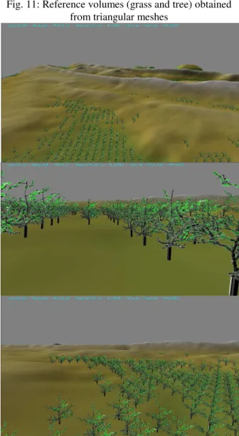
All the computations are done on a P4 at 3.0 GHz with a GeForce FX 5200 graphic card with 128 Mb of memory. Fig. 10 represents two reference volumes generated by voxels colouring technique which uses the information of depth accompanying each pixel by an image source, once volumes obtained they are translated into a whole of layers. The image (fig. 10a) is regenerated by using six images of depth which resolution is 256x256 pixels. In this case, there are 8.597 coloured voxels between 262.144 voxels (643) for a computing time 3,52 seconds. The images (fig. 10b) are obtained in the same way with 12 coloured key images and 1283 voxels, and in figure 11 we have two other volumes of reference constructed by using a voxels colouring starting from a triangular grid (or cloud of points).
Fig. 12 shows a whole of views taken from different points of vision. It represents complex terrain made up of 10.000 patches built from a Perlin texture equipped by trees. The frame rate is 20 to 30 fps depending on the view and the tuning of parameters. The frame rate is inversely proportional to resolution, and transitions between LODs of the same type of slices are quite unnoticeable. Rendering is carried out in an interactive time when the displaying frequency varies between 9
and 21 F.P.S and the reference volume resolution is
1283. Fig. 12 : Different view position of a terrain of 10.000 patches equipped with trees
(a) (b)
Fig. 10:Reference volumes obtained by using the voxels coloring technique.
Fig. 11: Reference volumes (grass and tree) obtained from triangular meshes
CONCLUSION AND FUTURE WORK
We have described a multiscale scheme for real-time volumetric textures by integrating new way to represent reference element: the voxel colouring technique, which permits to generalize the use of the texel to objects defined only by key images (real photographs or images obtained by a synthesis process). To map texel over surface support, we use technique based on image layers [2] that was particularly effective and is well adapted to visualization of volumetric textures using graphics board. We have shown that our results are convincing: we can move interactively above a scene which shows a continuous range reference element. However, it still remains of certain points to improve:
- The use of three directions of layers extends three times the memory capacity used to store the reference volume, what results in an increase in the space occupied in the memory textures.
- Generalization of the scene to be equipped with other types of surface and introduction of 3D textures. [24]
- Generating local illumination on texel by integrating image based rendering techniques using graphics capabilities.
- Animation of volumetric textures.
REFERENCES
1. Decaudin, P. and Neyret, F., 2004. Rendering Forest Scenes in Real-Time. In Eurographics Symposium on Rendering.
2. Meyer, A. and Neyret, F., 1998. Interactive volumetric textures. In Eurographics Rendering Workshop, pp: 157-168.
3. Kajiya, J. and Kay, T., 1989. Rendering fur with three dimensional textures. Proceedings of SIGGRAPH’ 89, vol. 23, N° 3, pp: 271- 280. 4. Neyret, F., 1998: Modeling animating and
rendering complex scenes using volumetric textures. IEEE Transactions on Visualization and Computer Graphics, vol. 4, N° 1.
5. Lacroute, P. and Levoy, M., 1994. Fast volume rendering using a shear–warp factorization of the viewing transformation. Proceedings of SIGGRAPH ’94, pp: 451–458.
6. Westermann, R. and Ertl, T., 1998. Efficiently using graphics hardware in volume rendering applications. Proceedings of ACM SIGGRAPH, pp: 169 - 178.
7. Schaufler, G., 1998. Image-based object representation by layered impostors. ACM Symposium on Virtual Reality Software and Technology ’98, pp: 99–104.
8. Lengyel, J., Praun, E., Finkelstein, A. and Hugues, H., 2001. Real-Time Fur over Arbitrary Surfaces. Symposium on Interactive 3D Graphics, pp: 227-232.
9. Decoret, X., Durand, F., Sillion, F. X., and Dorsey J., 2003. Billboard clouds for extreme model simplification. Proceedings of ACMSIGGRAPH, ACM Press, vol. 22, N°3, pp: 689-696.
10. Jakulin, A., 2000. Interactive Vegetation Rendering with Slicing and Blending. Proc. eurographics (Short Presentations)
11. Sénégas, F., 2001. Rendu de forêts en temps-réel à base de représentations alternatives. Rapport de DEA IVR, INPG.
12. Levoy, M. and Whitted, T., 1985. The use of points as a display primitive. TR 85-022. CS Department, University of North Carolina.
13. Grossman, J. P. and Dally, W. J., 1998. Point sample rendering. EG workshop on rendering, Springer-Verlag. pp: 181–192.
14. Pfister, H., Zwicker, M., van Baar, J., and Gross, M., 2000. Surfels: Surface elements as rendering primitives. Proc. ACM SIGGRAPH. pp: 335–342. 15. Gross, M., Pfister, H., Zwicker, M., Pauly, M.,
Stamminger, M., and Alexa, M., 2002. Point based computer graphics. In Tutorial T6, Eurographics. 16. Rusinkiewicz, S. and Levoy, M., 2000. Qsplat : A
multiresolution point rendering system for large meshes. Proceedings of conference on Computer graphics and interactive techniques. pp: 343-352. 17. Zwicker, M., Gross, M., Pfister, H., and van Baar,
J., 2001. Surface splatting. Proceedings of the 28th annual conference on Computer graphics and interactive techniques. pp: 371-378.
18. Guennebaud, G. and Paulin, M., 2003. Efficient screen space approach for Hardware Accelerated Surfel Rendering. In Vision, Modeling and Visualization, Munich, pp: 485-495.
19. Ren, L., Pfister, H., and Zwicker, M. 2002. Object space ewa surface splatting: A hardware accelerated approach to high quality point rendering. Eurographics, vol 21, N°3 pp: 461- 470. 20. Guennebaud, G., Paulin, M. 2002. Visualisation
par surfels des textures volumiques. AFIG 2002, pp: 117- 128.
21. Seitz, S. M. and Dyer, C. R., 1997. Photorealistic Scene Reconstruction by Voxel Coloring, Proc. Computer Vision and Pattern Recognition Conf., pp: 1067-1073.
22. Miller, N., 2000. OpenGL Texture Mapping : An Introduction,http://www.gamedev.net/reference/pro gramming/features/ogltm/.
23. Porter, T. and Duff, T., Compositing Digital Images. 1984. Computer Graphics Volume 18, N° 3, pp: 253 – 259