VARIABLE SPEED SYNCHRONOUS CONDENSER USING
DOUBLY-FED INDUCTION MACHINE
Antonio Carlos Ferreira
∗Luciano Moraes de Souza
∗Edson H. Watanabe
∗∗Universidade Federal do Rio de Janeiro, COPPE – Programa de Engenharia El´etrica,
P.O. Box 68.504 21.945-970 - Rio de Janeiro - RJ
ABSTRACT
The wound rotor induction machine (WRIM) presents characteristics that make it attractive as an energy stor-age system where the energy is stored as kinetic energy in the rotor moving parts. When operating in the dou-bly fed mode (DFIM), with the rotor fed by a variable frequency power converter, the WRIM behaves as a syn-chronous machine, differing from the latter in the vari-able speed operation and larger dumping effect when subjected to disturbances. As the converter only needs to be designed to handle a fraction of the total power, the system can be used at a high level of power. This paper presents the analysis of a Doubly Fed Induction Machine (DFIM) used as a controlled active and reactive power compensator. The simulation and experimental results obtained show that this system can be used for voltage control in a power system as well as load-leveling device.
KEYWORDS: Power quality, voltage sags, doubly-fed
machines
RESUMO
A m´aquina de indu¸c˜ao de rotor bobinado (MIRB) apre-senta caracter´ısticas que a tornam atrativa para
aplica-Artigo submetido em 31/01/02
1a. Revis˜ao em 15/08/02, 2a. Revis˜ao em 01/04/03
Aceito sob recomenda¸c˜ao do Ed. Assoc. Prof. Denizar C. Martins
¸c˜ao em sistemas de armazenamento cin´etico de energia. Quando operando no modo de dupla alimenta¸c˜ao, com o rotor sendo alimentado por um conversor eletrˆonico de potˆencia, a MIRB se comoprta como uma m´aquina s´ıncrona, com a diferen¸ca de poder operar com velo-cidade vari´avel e apresentar um maior amortecimento quando submetida a dist´urbios. O fato do conversor precisar processar apenas parte da potˆencia total do sis-tema favorece sua aplica¸c˜ao em n´ıveis de potˆencia mais elevados. Este artigo analisa a aplica¸c˜ao da M´aquina de Indu¸c˜ao Duplamente Alimentada como um compen-sador control´avel de potˆencias ativa e reativa. Os re-sultados, experimentais e de simula¸c˜ao, apresentados, indicam que este sistema pode ser usado no controle de tens˜ao e no balan¸co de potˆencia em um sistema el´etrico.
PALAVRAS-CHAVE: Qualidade de energia,
afundamen-tos de tens˜ao, m´aquina de dupla alimenta¸c˜ao.
1
INTRODUCTION
re-ceiving attention and are being proposed for voltage and frequency control (Weissbachet alli 1999; Akagi, 2000).
When using a wound rotor induction machine (WRIM), with the stator connected to the grid and the rotor fed by a power converter, this converter only needs to be rated for a fraction of the total system power. There-fore, this system may be useful in the application at high levels of power (above hundreds of MVA). Also, the possibility of operating at variable speed in conjunc-tion with the power converter control make the machine present higher dumping factor of the oscillations due to faults in the grid when compared to a conventional syn-chronous machine system, where the speed is fixed by the grid frequency (Shafer and Simond, 1998). As the WRIM can withstand higher speed variations it can ex-change higher amount of energy with the grid and help to restore the energy balance. Also, with an appropri-ate converter control , which can control the frequency of the imposed rotor currents, the machine can be brought back to its initial operating point faster than the con-ventional synchronous machine.
Recently, the use of a Doubly Fed Induction Machine (DFIM) as a variable speed synchronous condenser (VSSC) was presented by Ferreiraet alli (2000). It has been shown that the VSSC can be used to control its ter-minal voltage by controlling the capacitive or inductive reactive power. This control is achieved by the adjust-ment of the converter output voltage. It has also been shown how the system can work as a low speed flywheel generator, being able to supply or absorb active power and the de-coupling of these two controls has been sug-gested.
The aim of this paper is twofold. Firstly an analytical model of the DFIM will be developed. This model will be used to demonstrate how the power factor of the sta-tor winding can be controlled by the converter. This analysis will be confirmed with simulations and labo-ratory measurements on a 3 HP machine. Secondly, a vector control scheme which de-couples the reactive and active power control will be presented This control will be validated by simulations based on SABER? simula-tor.
2
POWER FACTOR CONTROL
Figure 1 shows a steady-state equivalent circuit for the DFIM. This equivalent circuit can be used to analyze the effect of the converter output voltage on stator winding power. The following assumptions ca be made: fixed stator winding voltage and constant rotor voltage fre-quency, as imposed by the converter.
^ Vs
rs j Xs j Xr
j Xm
rr s
^ Vr s
Figure 1: DFIM equivalent circuit
where:
ˆ
Vs: Stator voltage;
ˆ
Vr: Rotor voltage referred to the stator;
rs: Stator resistance;
rr: Rotor resistance referred to the stator;
Xs: Stator leakage reactance;
Xr: Rotor leakage reactance referred to the stator;
Xm: Magnetizing inductance;
s: rotor slip.
With the previous assumptions, the equivalent circuit can be further simplified if we use Thevenin’s Theorem. Therefore defining
ˆ
VR=
ˆ
Vr
s
jXm rr
s +j(Xm+Xr)
(1)
and
rR+jXR=
rr
s +jXr
//jXm (2)
where ˆVR is the equivalent Thevenin voltage and rR+
jXRis the equivalent Thevenin impedance. We can also
write
ˆ
Vs= ˆVR+ (R+jX) ˆIs, (3)
where:
¯
Z=R+jX= (rs+rR) +j(xs+xR) =Z∠θ. (4)
Defining:
ˆ
V =Vs∠0 as reference voltage;
ˆ
VR=VR∠−δ as internal voltage; ˆ
whereφis the power factor angle, the power in the stator winding can be calculated as
S=P+jQ= 3 ˆVsIˆs∗ = 3VsIscosφ+j3VsIssinφ. (5)
Writing the currentIs as a function of Vs, VR and Z,
and substituting in (5) results in the expression for the power absorbed from the system
P = 3V
2
s
Z2R+ 3 VsVR
Z sin (δ−α) (6)
and
Q= 3V
2
s
Z2X−3 VsVR
Z cos (δ−α), (7)
where:
α= 90−θ.
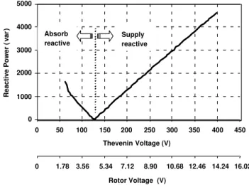
Equations (6) and (7) can now be used to investigate the effect of the rotor voltage on the stator winding power factor, assuming that the active power is constant. If the rotor voltage is increased, from (6), the term sin (δ−α) will have to be decreased. Therefore cos (δ−α) will be increased and so will the second term on the right hand side of (7). In (7) we see that the reactive power is composed of two components. One depends only on the stator voltage and the machine parameters and is constant for a fixed voltage. The other depends on sta-tor and rosta-tor voltages and the cosine of the Thevenin voltage phase minus the impedance angle. Keeping the active power constant, we can generally find a value for the rotor voltage, which will cancel the reactive power in (7). From this value, an increase in the rotor voltage will result in a negative value for Q, which means that the machine is generating capacitive reactive power to the grid (the sink convention was assumed in the devel-opment of the model). Decreasing the rotor voltage will result in a positive value for Q, therefore the motor will be generating an inductive reactive power.
This analysis can be better illustrated in Figure 2 which shows simulated results relating the reactive power in the stator of a DFIM to the voltage applied to the ro-tor. The machine is connected to an infinite bus and for a fixed value of rotor voltage frequency (namely 1.0 Hz) the converter voltage was varied. For the simulated motor the turns ratio between stator and rotor windings is equall to one, therefore Vr in Figure 2 is the actual
rms voltage applied to the rotor.
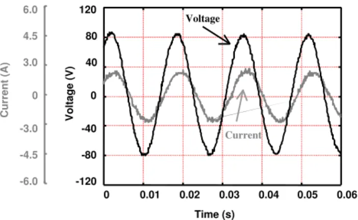
The same behavior can be seen in Figures 3, 4 and 5 which show measurements of stator voltage and current
0 1000 2000 3000 4000 5000
0 50 100 150 200 250 300 350 400 450
Thevenin Voltage (V)
Reactive Power (
var
)
0 1.78 3.56 5.34 7.12 8.90 10.68 12.46 14.24 16.02
Rotor Voltage (V) Supply reactive Absorb
reactive
Figure 2: Variation of stator reactive power with rotor voltage
0 0.01 0.02 0.03 0.04 0.05 0.06 -120
-80 -40 0 40 80 120
Time (s)
Voltage (V)
-6.0 -4.5 -3.0 0 3.0 4.5 6.0
Current (A)
Voltage
Current
Figure 3: Stator voltage and current (unity power fac-tor)
0 0.01 0.02 0.03 0.04 0.05 0.06
Time (s) -120
-80 -40 0 40 80 120
Voltage (V)
-6.0 -4.5 -3.0 0 3.0 4.5 6.0
Current (A)
Voltage
Current
Figure 4: Stator voltage and current (lagging power fac-tor)
0 0.01 0.02 0.03 0.04 0.05 0.06
Time (s) -120
-80 -40 0 40 80 120
Voltage (V)
-6.0 -4.5 -3.0 0 3.0 4.5 6.0
Current (A)
Voltage
Current
Figure 5: Stator voltage and current (leading power fac-tor)
3
VOLTAGE CONTROL
Ferreiraet alli (2000) presented some simulation results for the application of the DFIM as a synchronous con-denser, controlling the voltage in a power system. The rotor voltage was directly controlled and the rotor fre-quency was kept constant. Figure 6 shows the labora-tory test rig, which was used to validate those simula-tions. The system consists of a DFIM, which is fed from the mains via a three-phase autotransformer. The in-ductors between the machine and the transformer are used to ensure that there is a voltage difference between these two terminals. The rotor is fed from a commercial inverter, which works with constant V/f ratio. As the control scheme relies on a fixed frequency/variable volt-age characteristics, the second autotransformer is used to control the converter input voltage, therefore the DC link voltage. It should be pointed out that this was a
simple laboratory set-up used just to validate the study.
The test consists in reducing the first transformer volt-age in order to reduce the voltvolt-age at the machine ter-minals, simulating a fault on the supply system. After that the converter output voltage is varied in order to bring the stator voltage back to its initial level. This can be seen in Figure 7, which shows the voltage at the compensator terminals measured by an oscilloscope. Figure 7 shows that until t=1.2 seconds the DFIM sta-tor voltage is around 98.3 Vrms when it is decreased approximately 10 %. At t=2.7 seconds the rotor volt-age is increased from 5.5 Vrms to 9.0 Vrms which brings the stator voltage to its pre-fault level. The effect of the reactive power in the stator winding of the DFIM on its terminal voltage can be seen in 4, which shows the instantaneous three phase reactive power calculated from the measured values of voltage and current. Due to converter limitations, which limited the voltage range applied to the rotor, it was not possible to adjust the system to operate with a unity power factor before the voltage was reduced, as it would normally be the case. Therefore, in this test the voltage was restored with a reduction in the reactive power absorbed by the DFIM
Converter Variac
Variac
MIRB Inductor
System Plug
1 2
Power Electronics Laboratory
Figure 6: Laboratory test rig.
4
VECTOR CONTROL
-160 -80 0 80 160
0 0.5 1.0 1.5 2.0 2.5 3.0 3.5 4.0
Time (s)
Voltage (V)
Figure 7: Phase voltage at DFIM terminal.
800
600
400
200
0
-200
0 0.5 1.0 1.5 2.0 2.5 3.0 3.5 4.0
Time (s)
Reactive Power (var)
Figure 8: Reactive power in the stator.
In this analysis, a mathematical model of the symmetri-cal DFIM is used, where instantaneous values of voltage and current at the stator and rotor windings phases, va, vb, vc, vA, vB, vC and ia, ib, ic, iA, iB iC, are
transformed to an arbitrary reference frame using Park’s transformation as in Figure 9, where
a,b,c, refer to the magnetic axis of the stator phases;
A,B,C, refer to the magnetic axis of the rotor phases;
d,q, arbitrary rotating reference frame.
As shown by Krause (1986), the machine can be modeled by a set of equations, which relates applied voltages to
a s
r b
c
A B
C d
q
Figure 9: Park’s transformation.
voltage drops and flux linkages as
vds=rsids+
d dtλds−
dθs
dt λqs (8)
and
vqs=rsiqs+
d dtλqs+
dθs
dt λds (9)
where, vds and vqs are the stator voltage components.
λdsandλqs are stator flux linkages components and are
given by
λds=Lsids+Msridr (10)
and
λqs=Lsiqs+Msriqr (11)
where ids and iqs are the stator current components.
A similar set of equations may be written for the rotor where the suffix “r” refers to rotor quantities. Therefore
vdr=rridr+
d dtλdr−
dθr
dt λqr, (12)
vqr =rriqr+
d dtλqr+
dθr
dt λdr, (13)
λdr=Lridr+Msrids (14)
and
λqr =Lriqr+Msriqs. (15)
The above system of equations is general and can be used for any reference frame. For example, taking the magnetic axis of stator phase “a” as reference, and sub-stituting it for the flux linkages, it can be written
vs=rsis+Ls
d
dtis+Msr d dt
irejθ
where
vs=vds+jvqs,
is=ids+jiqs, (17)
and
ir=idr+jiqr
Defining the leakage factorσs, whereLs= (1 +σs)Msr,
we may write:
vs=rsis+Msr
d dt
(1 +σs)is+irejθ
. (18)
As presented by Leonhard (1997), with a proper choice of a reference frame, the control of active and reactive power in the stator can be decoupled and be imple-mented by controlling the two components of the rotor current. In this paper the reference frame proposed by Leonhard (1997) is used, where the “d” axis is aligned with an extended magnetizing current vector responsi-ble for the stator flux including stator leakage, defined as
ims=ims(t)ejµ(t)= (1 +σs)is+irejθ. (19)
Substituting from (19) into (18) gives
Ts
d
dtims+ims=vs
(1 +σs)
rs
+irejθ. (20)
Working with the “d” and “q” components, we may write
Ts
d
dtims+ims=vds
(1 +σs)
rs
+idr (21)
and
dµ
dt =ωms =
1
Tsims
vqs
1 +σs
rs
+iqr
(22)
whereTsis the time constant of the stator circuit, which
are used in the calculation ofµas in Figure 10. There-fore, with this choice of a reference frame, the stator reactive power is related to the “d” component of the rotor current and the active power is related to the “q” component as indicated in 4.1.
4.1
Reactive Power Control
The control implemented relies on the knowledge of the reactive component of the stator current. In this work this component is calculated using the instantaneous
iA “ABC” to “dq” iB iC s sT 1 1 s T sin cos sin cos s 1 measured s 1 s s s s R 2 V 2 3 1 qr i dr i ms ms i
Figure 10: Field orientated control.
Controller PI measured + _ ref. Controller PI ireactive + _ iref. iqc idc Clarke’s Transformation Stator Current Stator Voltage “dq” to “ABC” C R -P W M DFIM Rotor
Figure 11: Decoupled control.
power theory (Akagiet alii, 1983). This can be easily accomplished if we transform the instantaneous values of voltage and current at the stator windings phases, va,
vb, vcand ia, ib, ic, to a stationary reference frame using
Clarke’s transformation v0 vα vβ = 2 3
1√2 1√2 1√2 1 −1/2 −1/2 0 √3/2 −√3/2
× va vb vc (23) and i0 iα iβ = 2 3 2 3
1√2 1√2 1√2 1 −1/2 −1/2 0 √3/2 −√3/2
The reactive power can be calculated from
p q
=
vα vβ
vβ −vα
iα
iβ
(25)
Defining ∆ =v2
α+v2β it can be written
iαreactive
iβreactive
= 1 ∆
vα vβ
vβ −vα
0
q
, (26)
from where the reactive power component of the stator current can be calculated as
ireactive =
i2
α+i2β. (27)
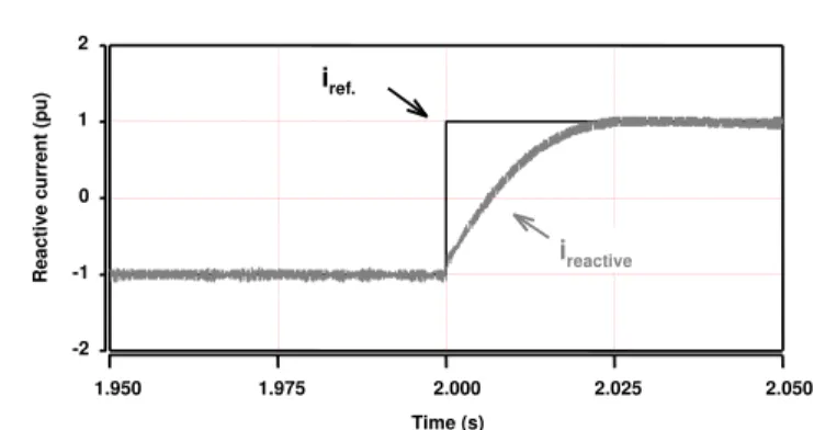
Figures 12, 13 and 14 show simulated results where a variation of the “d” component of the rotor voltage is applied. The rotor is supplied with a Current Regu-lated Pulse Width Modulation Converter (CR-PWM). Figure 12 shows that at t=2.0 seconds there is a step change in the reactive current reference from -1 pu to +1 pu and Figure 13 shows that this is followed by a similar change in the stator reactive power. 4.2 shows a negligible variation on the rotor speed as expected from the decoupled control.
4.2
Operation as a load leveling device
One of the great advantages of the system using a DFIM is that the kinetic energy stored in the rotating parts can be used to supply or absorb active power from the grid. This, however, can be done for a limited period of time, despite the absence of any mechanical device connected to its shaft and using a power converter rated for a fraction of the total power. Considering the kinetic energy stored at two different speeds
W1=
1 2Jω
2
1Joules (28)
and
W2=
1 2Jω
2
2Joules (29)
whereW is the kinetic energy stored in the rotor,ωis its angular speed in rad/s andJ its total inertia in kg.m2.
If the rotor speed can be varied over a time interval, the stored energy will vary as
∆W =W2−W1Joules (30)
and will cause an active power flow given by
P = ∆W
∆t =
1 2J
(ω2 2−ω21)
∆t W atts (31)
-2 -1 0 1 2
1.950 1.975 2.000 2.025 2.050
Reactive current (pu)
Time (s)
ireactive iref.
Figure 12: Simulated reactive component of stator cur-rent.
-2 -1 0 1 2
1.950 1.975 2.000 2.025 2.050
Reactive Power (pu)
Time (s)
Figure 13: Simulated reactive power in the stator.
1784 1785 1786 1787
1.950 1.975 2.000 2.025 2.050 2.075 2.100 2.125 2.150
Speed (rpm)
Time (s)
1760 1770 1780 1790 1800
1.350 1.375 1.400 1.425 1.450 1.475 1.500
Time (s)
Speed (rpm)
Figure 15: Simulated DFIM speed variation.
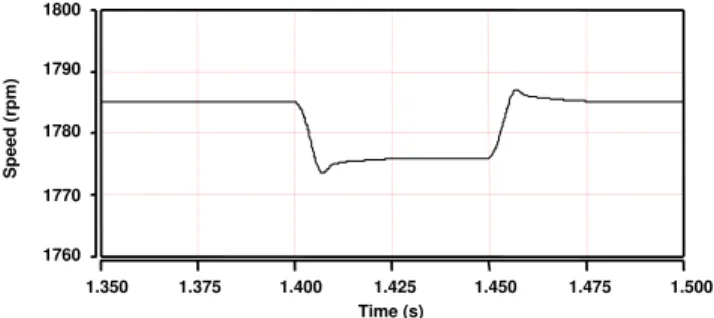
Equation (31) indicates that if the rotor speed is reduced the energy difference will be transformed in active power and will be supplied to the grid. On the other hand, in order to increase the rotor speed, energy will have to be extracted from the grid in the form of active power. Equation (31) also suggests a relationship between the active power in the stator and the speed variation, which can be used in the decoupled control presented in 4.1. This can be seen in Figures 15, 16 and 17, which show the effect of a step change in the rotor speed reference (ωref in Figure 11). Figure 15 shows that step changes
were imposed at t = 1.4 seconds and 1.46 seconds. Fig-ures 16 and 17 show the effect of those changes on the rotor current “q” component and therefore on the active power flow in the stator windings. 6 shows the variation of the current in the stator windings. It should be noted that the step changes were imposed just as a proof of concept. The development of a control algorithm which will relate speed variations with the required stator ac-tive power is currently under study.
5
CONCLUSIONS
This paper presented a detailed analysis of a doubly fed induction machine (DFIM) to be used as a variable speed synchronous condenser (VSSC). It was shown that the VSCC can replace the conventional synchronous condenser in reactive power compensation with the ad-vantage of being able to provide short time active power compensation. It is the authors opinion that this system will be very useful to guarantee electric energy quality in some points of the grid where high fluctuation of the load is present.
6
ACKNOWLEDGEMENTS
This work is supported by a FINEP/PRONEX grant.
-4.0 -2.0 0.0 2.0 4.0
1.350 1.375 1.400 1.425 1.450 1.475 1.500
Current (pu)
Time (s)
iqc
iqr
Figure 16: Simulated active power component of rotor current.
-4.0 -2.0 0.0 2.0 4.0
1.350 1.375 1.400 1.425 1.450 1.475 1.500
Current (pu)
Time (s)
iqc
iqr
Figure 17: Simulated active power in the stator.
-20 -10 0 10 20
1.350 1.375 1.400 1.425 1.450 1.475 1.500
Current (A)
Time (s)
Figure 18: Simulated stator current.
REFERENCES
Bolen, M.H.J. Bolen (1992). Understanding Power
Quality Problems, IEEE Press, New York
Ter-Gazarian, A. (1994).Energy Storage for Power Sys-tem. IEE Series 6, Great Britain.
Weissbach, R.S., G.G. Karady and R.G. Farmer (1999). “Dynamic voltage compensation on distribution feeders using flywheel energy storage”,IEEE
Akagi H. (2000). “Active Filters and Energy Storage Systems Operated under Non-Periodic Conditions”, IEEE Summer Meeting.
Shafer D., J.J.Simond (1998). “Adjustable Speed Asyn-chronous machine in Hydro Power plants and its advantages for the electric grid stability”, Cigr´e
Paris Session, Paris.
Ferreira, A.C., L.M. de Souza and E. H. Watanabe (2000,). “Voltage Control Using Variable Speed Synchronous Condenser”, in IV Industry
Applica-tions Conference, vol 2, pp. 703-708, Porto Alegre,
Brazil
Leonhard, W. (1997). Control of Electrical Drives, Berlin Springer, Germany
Akagi, H. Y Kanazawa and A. Nabae (1983). “General-ized Theory of the Instantaneous Reactive Power in Three Phase Circuits”, in Proceedings of the
IPEC’83 – Int. Power Electronics Conf., Tokyo, pp.
1375-1386