Transactions of the VŠB – Technical University of Ostrava, Mechanical Series No. 1, 2012, vol. LVIII
article No. 1891
Radek ČADA*, Petr TILLER**
SPRINGBACK ANALYSIS OF INTRICATE SHAPE STAMPING FROM VARIOUS MATERIALS WITH THE USE OF FINITE ELEMENTS METHOD
ANůLÝZů ODPRUŽENÍ VÝTůŽKU NEPRůVIDELNÉHO TVůRU Z R ZNÝCH
MůTERIÁL SVYUŽITÍM METODY KONEČNÝCH PRVK
Abstract
Paper concerns drawing operation including related consequent springback of intricate shape stamping from thin sheet-metal – internal reinforcement of car bodyshell B-pillar in order to keep after drawing process the dimensions and tolerances of stamping after drawing process which are given in part drawing. Simulation of drawing process and consequent springback simulations were carried out in CAE software PAM-STAMP 2G 2011 which uses finite element method. In contribution the drawing process simulation of car bodyshell B-pillar is detailly described in this program, choice of suitable solver for separate drawing simulation stages, consequent springback simulations for four strip steels with the use of two mesh strategies and their mutual comparison. For given stamping shape the best strip steels were evaluated from point of view of drawability and reaching minimal springback size. In the end of the paper the method of tuning of sizes of drawing tool in order to achieve the state when final stamping deviations will correspond to tolerances specified at part drawing is described.
Abstrakt
Článek se týká řešení operace tažení včetně stím souvisejícím následným odpružením výtažku nepravidelného tvaru ztenkého plechu –vnitřní výztuhy B-sloupku karosérie automobilu zaúčelem
dosažení poprocesu tažení rozměr a tolerancí výtažku, které jsou předepsány navýkresu součásti. Simulace plošného tváření a následné simulace odpružení byly prováděny svyužitím programu
PAM-STAMP 2G Ň011, který využívá metodu konečných prvk . Včlánku je podrobně popsána
simulace procesu tváření B-sloupku karosérie automobilu v tomto programu, volba vhodného řešiče pro jednotlivé etapy simulace, následné simulace velikosti odpružení pro čtyři druhy pásových ocelí
při použití dvou zvolených meshovacích strategií a jejich vzájemné porovnání. Pro daný typ výtažku
byly vyhodnoceny nejvhodnější pásové oceli zhlediska lisovatelnosti a dosažení minimální velikosti
odpružení. Vzávěru článku je popsán zp sob ladění rozměr tažného nástroje zaúčelem dosažení stavu, kdy tvarové odchylky konečného výtažku odpovídají předepsaným tolerancím navýkresu součásti.
INTRODUCTION
Among areas that are dynamically developing in terms of advanced technology applications in an effort to keep pace with competitors the mechanical engineering belongs, especially the automotive industry. In the field of sheet-metal forming the use of simulation software that can
*
prof. Ing. Radek ČůDů, CSc., VŠB– Technical University of Ostrava, Faculty of Mechanical Engineering, Department of Mechanical Technology, 17. listopadu 15, 708 33 Ostrava-Poruba, Czech Republic, tel.: +420 59 7323289, fax: +420 59 6916490,e-mail: [email protected]
**
simulate of forming process on the basis of Finite Element Method (FEM) is already considered a standard. Finite Element Method is a numerical method for the analysis of structures and objects. The basic principle of Finite Element Method is discretization of the body on a small area (elements) that are easily described mathematically. Finite Element Method is considered the most powerful in the present method of mathematical modelling in sheet-metal forming processes. Its advantage is the possibility of using for analyzing a wide range of tasks without any restrictions. During solving problems system of equations plasticity theory – the equation equilibrium forces, the flow continuity equation, constitutive equation is used. Based on the results of simulations by CAE (Computer-Aided Engineering) softwares the time of tools preparation and the technological process of stamping production can be shortened.
According to the automation increasing and challenging production systems integrity where handling systems are interconnected with presses the stampings springback plays an important role. Keeping of dimensional and shape deformations is complicated by the occurrence of flexibly deformed part. Springback is very difficult to predict, therefore numerical simulation of springback is very interesting from a practical point of view in succession to the deep-drawing process. To re-create a static equilibrium of the stamping to draw simulation results that are calculated by explicit dynamic solver, transferred to a static default program is necessary. By introducing of the balance of forces the separate elastic parts in stamping realize springback.
New materials provide additional requirements at stampings drawing technology because they have different values of springback, other deformation forces and deformation capacity. For their assessment the standard absolute values of the material are not appropriate but their relative values related to the specific weight of used material. These factors play an important role at manufactures at consideration of technology for manufacture the parts. For tuning of dimensions of tools for production an intricate shape stamping with dimensions and tolerances of compliance imposed on production drawing the emphasis should be on the shape deviations arising after drawing and after subsequent springback of stamping. It is also to be taken operations like cut-out hole, bending in progressive drawing tools that must be individually fine-tuned according to specific conditions of the technological process of drawing.
Nowadays the market offers several simulation systems based on Finite Element Method. To determine springback size of selected materials the model of intricate shape stamping – internal reinforcement of car bodyshell B-pillar was chosen which was created by the client in software CATIA V5 R19. For stamping model modifying for drawing process simulation the software Solid Works 2008 was used. Both softwares mentioned above are among the product group 3D CAD of Dassault Systémes. For calculation and drawing process simulation of the internal reinforcement of car bodyshell B-pillar CAE software PAM-STAMP 2G 2011 of company ESI Group was used. The company MECAS ESI, s. r. o. is the licensor at the Czech market.
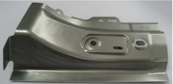
1 INTERNAL REINFORCEMENT OF CAR BODYSHELL B-PILLAR
Fig. 1 Internal reinforcement of car bodyshell B-pillar.
The stamping in digital format CAT Part (Computer-Aided Translation) created by client in software CATIA V5 R19 (see Fig. 2) was the starting model for examination of springback size of selected strip steels. This digital model of stamping fully describe its resulting shape and size including accuracy while at the bottom flat flange side the dimensional tolerance is ±0.5 mm (see Fig. 1) and in other places of stamping the dimensional tolerance is ±0.8 mm. These tolerances are essential for evaluation of springback size of selected materials. The model includes stated fixed points of RPS (Reference Point System) for measuring the complex shapes that are not otherwise measurable. For evaluation of stamping critical dimensions springback and with them related part of drawing tools dimensions and for subsequent tests of real stamping drawing four different strip steels with the same thickness of 0.65 mm were chosen, suitable for manufacture of the internal reinforcement of car bodyshell B-pillar.
Fig. 2 Model of internal reinforcement of car bodyshell B-pillar in digital format CAT Part of software Catia V5 R19 with marked RPS points (three blue rectangles).
It is continuously hot-dip coated flat steels HX220YD, HX220BD and DX54D according to
Chemical composition and mechanical properties of separate steels are given by standards
ČSN EN 10346 and ČSN EN 10268.
Chemical composition of strip steels is listed in Tab. 1. The required values for drawing process simulation, i.e. mechanical properties, the coefficients of the plastic anisotropy rx, the values
of weighted average of plastic strain ratio r and the degree of planar anisotropy of plastic strain ratio
Δr of strips from steels HX220YD, HX220BD, DX54D and HC220P are listed in Tab. 2 and Tab. 3.
Tab. 1 Chemical composition of strip from steels HX220YD, HX220BD and DX54D for cold forming according toČSN EN 10346 and HCŇŇ0P according to ČSN EN 10268.
Steel types Chemical composition (weight %)
Mark of steel Numeric marking C max. Si max. Mn max. P max. S
max. Al celk
Nb max.
Ti max.
HX220YD 1.0923 0.01 0.20 0.90 0.08 0.025 ≤0.1 0.09 0.12
HX220BD 1.0919 0.10 0.50 0.70 0.06 0.025 ≤0.1 0.09 0.12
DX54D 1.0306 0.12 0.50 0.60 0.10 0.045 – – 0.30
HC220P 1.0397 0.07 0.50 0.70 0.08 0.025 0.015 – –
Tab. 2 Mechanical properties of strip from steels HX220YD, HX220BD and DX54D for cold forming according to ČSN EN 10ň46 and HCŇŇ0P according to ČSN EN 10268.
Steel types Mechanical properties
Mark of steel Numeric marking Surface finishing Re (MPa) Rm (MPa) A80 (%)
r90 min.
(–)
n90 min.
(–)
HX220YD 1.0923 +Z200 220 ÷ 280 340 ÷ 420 32 1.5 0.17 HX220BD 1.0919 +Z200 220 ÷ 280 340 ÷ 420 32 1.2 0.15 DX54D 1.0306 +Z200 120 ÷ 220 260 ÷ 350 34 1.4 0.18 HC220P 1.0397 +Z200 220 ÷ 270 320 ÷ 340 32 1.3 0.16
Tab. 3 Values of the plastic strain ratio rx in direction of 0°, 45° and 90°towards sheet-metal rolling
direction, the values of weighted average of plastic strain ratio r, degree of planar anisotropy of plastic strain ratio Δr of strip from steels HX220YD, HX220BD, DX54D and HC220P.
Mark steel Numeric marking r0 () r45 () r90 ()
r
() Δr ()HX220YD 1.0923 1.41 1.35 1.72 1.46 0.22
HX220BD 1.0919 0.98 0.92 1.30 1.03 0.21
DX54D 1.0306 2.22 1.82 2.60 2.12 0.59
HC220P 1.0397 1.75 1.05 2.14 1.50 0.90
The values of the strain hardening exponent nx in direction of 0°, 45° and 90° towards sheet
-metal rolling direction, the strain hardening exponent mean value nm, the planar anisotropy degree
of strain hardening exponent Δn of strips from steels HX220YD, HX220BD, DX54D and HC220P are listed in Tab. 4.
At the strip steel HX220BD the BH effect manifests (index BH2 min. 35 MPa in lateral
in the range from 170 °C after Ň0 minutes. These strip steels are suitable for cold forming and exhibit high resistance to permanent deformation that will increase at the finished parts during heat treatment. These steels are often used on external and transition parts from the exterior to the interior of car bodies.
Strip steel HC200P is determined for coating of metal coating by hot-dip coating or by electrolysis. Requirements for surfacing are governed by standard ČSN EN 10139.
Steel strip HX220YD is a type of IF steel without intercrystalic elements wihh high strength, specification in mark of steel – Y. They are steels with controlled composition to achieve better normal plastic strain ratio r and the strain hardening exponent nx.
Strip steels are delivered with types of coatings +Z, +ZF, +ZA, +AZ, +AS. In the part drawing the stamping surface is specified Z200 (see Tab. 2) that ranges in thickness interval (10 ÷ 20) μm and a density of surface finish layer of zinc is 7.1 g cm-3.
Tab. 4 Values of the strain hardening exponent nx in direction of 0°, 45° and 90° towards sheet-metal
rolling direction, the strain hardening exponent mean value nm, the planar anisotropy degree of strain
hardening exponent Δn of strip from steels HX220YD, HX220BD, DX54D and HC220P.
Mark steel Numeric marknig n0 () n45 () n90 () nm () Δn ()
HX220YD 1.0923 0.19 0.17 0.20 0.18 0.03 HX220BD 1.0919 0.16 0.15 0.18 0.16 0.02 DX54D 1.0306 0.19 0.23 0.22 0.21 -0.03 HC220P 1.0397 0.24 0.23 0.23 0.23 0.00
For processing of specified stamping in progressive drawing tool the coil of sizes (0.65x600) mm according to EN 10346 that correspond to ČSN EN 10346 (42 0110) with the name: Continuously hot-dip coated steel flat products – Technical delivery conditions is delivered. The standard specifies requirements for flat products in thicknesses from 0.35 mm to 3 mm.
For production of given stamping in progressive drawing tool the coil with dimensions of (0.65x600) mm according to EN 10268 that correspond to ČSN EN 10346 (42 0110) with the name: Continuously hot-dip coated steel flat products – Technical delivery conditions is delivered. The standard specifies requirements for flat products in thicknesses less than or equal 3 mm.
With regard to surface finish at strip steel HC220P, the standard ČSN EN 10268 for the width greater than or equal 600 mm refers to the requirements specified in standard EN 10139.
Strip steels are supplied in coils. An example of marking of the coil according to ČSN EN 10268 made from material HC220B (1.0397), surface quality of B, surface finish normal (m): Coil EN 10268-HC220B-B-m. Strip length is given by the weight of coil. Coils suppliers are the steel producers ThyssenKrupp Steel Europe AG and Voestalpine AG who guarantee the chemical composition and mechanical properties. Properties of these strip steels (see Tab. 1 and Tab. 2) correspond to the requirements in automotive industry. Drawing of stamping is performed on a hydraulic transfer press Schuler 250.
lifespan. The correct definition of input parameters for drawing process simulation and strain rate, size of blankholder force, lubrication have a decisive influence for tuning of stamping model in progressive drawing tool.
Drawing process simulation and subsequent springback was performed in software PAM-STAMP 2G 2011. This software belongs to a group of computer programs which are based on Finite Element Method. The software works with 3D model of stamping and blank. The model of die was imported in CAD format of file *.igs (Initial Graphics Exchange Specification) and blank was created directly in software PAM-STAMP 2G 2011. The calculation network is generated in environment of graphic pre-processor together with necessary boundary conditions of solution.
Two mesh strategies for monitoring influence of springback after drawing process simulation were chosen. Simulation model of drawing process simulation include three stages. These are stage of blank holding “Holding“, stage of stamping drawing “Stamping“ and final stage of stamping springback after drawing “Springback“ of stamping.
Defining of material and its properties is an essential part of the simulation model. In materials database the materials that are described in Chapter 1 were chosen. Their mechanical properties were verified by relevant tests. After discretization of surfaces into finite element mesh the separate drawing tool parts are assigned in drawing process. Before importing to software PAM-STAMP 2G 2011 all tool parts were centred into identical coordinate system that eliminates other time-consuming tool setting of individual tool parts.
2.1 Creation of stamping model for drawing process simulation
Default model provided by client was placed in the coordinate system that corresponded to the location of the given part at car bodyshell. For this reason the die model centring to new coordinate system called the global coordinate system (GCS) in software Solid Works 2008 was carried out. This coordinate system the software PAM-STAMP 2G 2011 also uses. Model of die was set up to required coordinate system that is the basis for drawing process simulation in software PAM-STAM 2G 2011. A negative Z-axis direction was chosen as drawing direction in coordinate system Global System.
2.2 Option of mesh strategies and set up of the contact type
After creation of simulation task it is necessary to choose the appropriate mesh strategy for deep-drawing process simulation of stampin of internal reinforcements of car bodyshell B-pillar before import model of die and each drawing tools by creating (punch and blankholder). For assessment of springback size the mesh strategies of tools “Springback“ and “Compensation” under the rules for setting calculation with springback were chosen.
For surfaces discretization into finite element mesh generated by mesh strategy the general rule is that radii on tools must be described by sufficient number of elements. At meshing of tool parts for springback calculation the recommended value for the maximum angle between adjacent elements is 7.5°. The maximum element size on blank in these mesh strategies is recommended 10 mm. Both chosen mesh strategies have default values of maximum angle between adjacent elements of 7.5° and the strategy “Springback“ has maximum element size of tool parts set to 30 mm (for rough calculation) and mesh strategy “Compensation“ has maximum element size of tool parts set to 10 mm.
At drawing tool the clearance between punch and die must be secured. Clearance of 10 % of sheet-metal thickness 0.65 mm was chosen, i.e. the value “Contact gap” of 0.065 mm. Blankholder must have vertical walls that was complied and wall height of 10 mm was chosen. This size was sufficient to run the drawing process simulation correctly.
Type of contact “Accurate“ was used in all stages of simulation “Holding“, “Stamping“ and
“Springback“ between separate tool parts.
2.3 Definition of drawing tool parts
has to be in range pp = (1.8 ÷ 2.8) MPa, the specific pressure pp = 2.6 MPa was selected. The punch
movement speed is according to recommendation of the technical literature in range between 0.4 ÷ 0.6 m s-1. The speed of 0.4 m s-1 was chosen due to material thickness and stamping size.
2.4 Defining of blank material
Calculated network of blank from sheet-metal is generated in the environment of graphic pre-processor together with boundary, contact and burdening conditions. Solution diagram of internal and external forces equations of motion equilibrium uses an explicit definition of finite element method. During the solution the consideration with non-linear deformation history sheet-metal of blank is taken into accoun. Description of the material behaviour is based on the Hill's formulation of the conditions of plasticity (Hill 1948). Therefore, when defining the material properties the menu
“Orthotropic Hill 48“ was used where the mechanical properties listed from Tab. 2 to Tab. 4 were defined. Another step after importing models of die and blank into the simulation program is the definition of material properties that must be entered before start of the calculation. Selection is made from programs material database or the material can be added according the test results and by that to improve the accuracy of simulation results.
For defining of material the Lankford coefficients r0, r45 and r90 towards sheet-metal rolling
direction α were used which can be determined from the formula:
t w r (), (1)
where are εw– logarithmic strain of the width and εt– logarithmic deformation of the length.
Defining of blank was performed for size of the grid “Mesh Size = 4“ with regard to size of blank. For blank the material properties of strips from steels HX220YD, HX220BD, DX54D HC220P and with a uniform thickness of 0.65 mm that are listed from Tab. 2 to Tab. 4 were entered.
At blank the type of calculation “Advanced Implicit“ was chosen with adaptive automatic networking “Automatic Refirement: Sliding Radius = 4“ for the calculation of springback. This is the size of smallest measured value of the radius on stamping from point of view of adaptive networking. The condition is that the deformed element size must be less than 25 % of total size of drawing radius and half of sheet-metal thickness.
For standard simulation calculation of drawing process is valid: ) 5 , 0 ( 5 ,
0 Rmin t
d (mm), (3)
For the calculation of springback is valid: ) 5 , 0 ( 25 ,
0 Rmin t
d (mm), (4)
where are d– stamping finite radius (mm), Rmin– minimum bending radius, t –material
thickness (mm).
2.5 Option of macro for springback calculation, calculation type and solver
For simulation drawing process and subsequent springback the macro “DoubleAction.ksa“ for precision calculations was chosen that is for accurate calculations to which the calculation of springback could be included.
Each stage of drawing process simulation “Holding“, “Stamping“ and “Springback“ requires different type of solver, therefore the function “Multi-host“ was used. This function very simplifies the simulation run and is essential in cases where is necessary to change the type of solver for given stage of drawing process simulations. The function allows to set up for different types of individual operations solver before running the simulation and calculations for each stage can continuously follow up on themselves, without interference by changing the definition of solver, that shortens the time of calculation.
For the stage of stamping springback “Springback“ for calculation of “Advanced Implicit“ the solver type of “SMP-DP“ (Shared Memory Process – Double Precision) was chosen. This is the method of double-precision calculation that on computational time is more demanding.
3 EVALUATION OF DRAWING PROCESS SIMULATION AND DEFINITION OF CRITICAL AREAS OF DEFORMATION
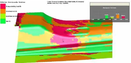
The stamping drawability analysis (see Fig. 3) shows a colour map of stamping deformation with the estimated size and the occurrence of wrinkling. Effort is to achieve at stamping the highest possible degree of deformation at fulfilling other conditions of simulation, i.e. low risk of failure, low thinning of the sheet-metal and the none occurrence of wrinkling. Deformed edge of stamping means less possibility of springback. Due to local material thicking the wrinkling of the stamping arises when using compared materials HX220YD, HX220BD, DX54D and HC220P.
Fig. 3 Results of drawability analysis of stamping of internal reinforcement of car bodyshell B-pillar including frequency histogram of individual areas using blanks from strip steel HC220P in software
PAM-STAMP 2G 2011 with chosen mesh strategy “Springback“.
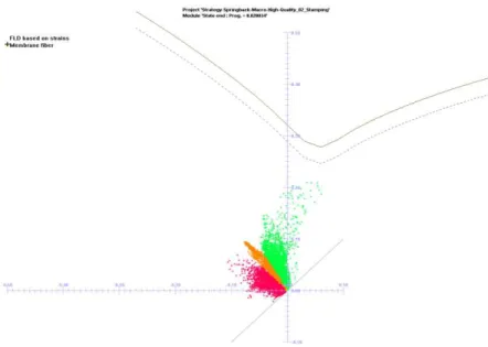
The secondary wrinkling in this case occurs at lower stamping stroke and in side of the stamping where the influence of tangential stress occurs the thicking of material. Analysis of stamping drawability using the forming limit diagram is shown on Fig. 4 where all evaluated states of strain detected at stamping lie in safe area in terms of the risk of crack in stamping. The forming limit diagram shows the maximum and minimum deviations of thicking from safe strain of given sheet-metal. The largest deviations from safe strain are in areas of material where pressing exists
Fig. 4 Forming limit diagram with limit strain curve of stamping of internal reinforcement of car bodyshell B-pillar using blanks from strip steel HC220P in software PAM-STAMP 2G 2011
with chosen mesh strategy “Springback“.
Fig. 5 Analysis of thickness as shown with frequency histogram of thickness and representation minimum and maximum values of thickness at critical areas of stamping of internal reinforcement of car bodyshell B-pillar using blanks from strip steel HC220P in software PAM-STAMP 2G 2011
with chosen mesh strategy “Springback“.
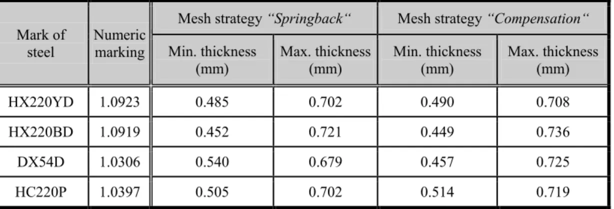
In Tab. 5 the comparison of thickness analysis results of stamping wall in critical areas for materials HX220YD, HX220BD, DX54D and HC220P with selected mesh strategies
“Springback“ and “Compensation“is seen.
Tab. 5 Comparison of thickness analysis results of wall of stamping of internal reinforcement of car bodyshell B-pillar using blanks from strip steels HX220YD, HX220BD, DX54D and HC220P.
Mark of steel
Numeric marking
Mesh strategy “Springback“ Mesh strategy “Compensation“
Min. thickness (mm)
Max. thickness (mm)
Min. thickness (mm)
Max. thickness (mm)
HX220YD 1.0923 0.485 0.702 0.490 0.708
HX220BD 1.0919 0.452 0.721 0.449 0.736
DX54D 1.0306 0.540 0.679 0.457 0.725
HC220P 1.0397 0.505 0.702 0.514 0.719
4 SPRINGBACK EVALUATION OF INTRICATE SHAPE STAMPING
Springback is one of stamping geometric defects. It can be described as unwanted additional strain of stamping, resulting from stress relaxation after unloading of stamping in forming tool. Dominant influence on the size of springback has especially a particular elastic deformation. In sheet-metal forming the angular changing of walls, side walls rotation, stamping rotation, edge warping, surface curvature and overall change of shape are geometric defects caused by springback.
4.1 Determination of RPS points, cut planes at stamping and comparison of separate stamping geometries with the dimensions at the part drawing
The RPS (Reference Point System) points and the RPS areas are auxiliary reference points that are used for the same establish of stamping according to measuring system. System of of RPS points defines the measuring base from which other dimensions are measured. RPS holes must be cut always in perpendicular direction according to stamping.
On the part drawing three RPS points were installed that were entered into springback simulation in software PAM-STAMP 2G 2011. For RPS 3 Fy point three degrees of freedom in directions TX, TY, TZ were bound; for RPS 4 Fy point two degrees of freedom in directions TY, TZ were bound and for RPS 5 Fy point one degree of freedom in direction TZ was bound.
For evaluation of springback size at stamping for both mesh strategies “Springback“ and
“Compensation“ a total of 20 section planes of 14.24 mm distance from each other according to overall dimensions of the stamping were selected. The planes were chosen in global coordinate system perpendicular to the X axis by reason the angular tracking changes between stamping and the forming tool after unloading of deformation force. The rotation of side walls that represents a curved incurred as the result of sheet-metal drawing over median radius, curvature of surface and overall shape change were also observed.
Fig. 6 Comparison of the nominal geometry shape (drawed red) with states to stamping geometry before springback (drawed blue) and geometry after springback (drawed green) of stamping internal
reinforcement of car bodyshell B-pillar using blanks from strip steel HC220P in software PAM-STAMP 2G 2011 with chosen mesh strategy “Springback“ and with selected cross section planes
on stamping and display shown RPS points (marked T-axis direction).
4.2 Evaluation of springback results and their comparison with 3D measurements For section sloping plane on the part drawing where the RPS points are entered, i.e. points of RPS 4 Fy and RPS 5 Fy, the tolerance of 0.5 mm is specified. In other parts of the stamping the tolerance of 0.8 mm is specified. Mutual evaluation of the nominal geometry of stamping shape without shape variations according to part drawing and stamping shape in state before springback after drawing process simulation for both mesh strategies “Springback“ and “Compensation“, the deviations between outline contours of nominal stamping geometry and stamping geometry from the state before springback ranged to 0.18 mm in selected sections of planes. This measured maximum value of deviation was found when using blank from strip steel HX220BD and in view of tolerances on the part drawing also with respect to measured deviations resulting springback geometry shape of stamping is negligible.
From practical point of view it is necessary to compare the springback size between nominal and springback geometry of stamping shape. For monitoring of resulting springback size the plane sections were selected in which the nominal geometry of the shape and geometry of springback stamping were compared. Selected section planes to monitoring springback size of nominal geometry of shape stamping and springback geometry of stamping are in Fig. 7, where for example of strip steel HX220BD with mesh strategy “Compensation“ the maximum values of deviations in the section plane are compared with tolerances specified on the part drawing.
Fig. 7 Comparison of nominal geometry stamping shape (drawed red) and spring-loaded geometry of stamping (drawed green) of internal reinforcement of car bodyshell B-pillar using blanks from
strip steel HX220BD in software PAM-STAMP 2G 2011 with chosen mesh strategy
“Compensation“ and marked RPS points.
Tab. 6 Comparison of the frequency tolerance deviations and frequency deviations in the lower zone of tolerance for steel strips HX220YD, HX220BD, DX54D and HC220P.
Mark of steel
Numeric marking
Mesh strategy “Springback“ Mesh strategy “Compensation“
Deviations in tolerance
(%)
Devitations in lower zone of tolerance
(%)
Devitations in tolerance
(%)
Deviations in lower zone of tolerance
(%)
HX220YD 1.0923 83.50 41.70 85.20 68.4
HX220BD 1.0919 83.80 40.60 88.30 50.0
DX54D 1.0306 88.90 63.60 91.24 50.1
HC220P 1.0397 38.53 22.53 82.28 26.3
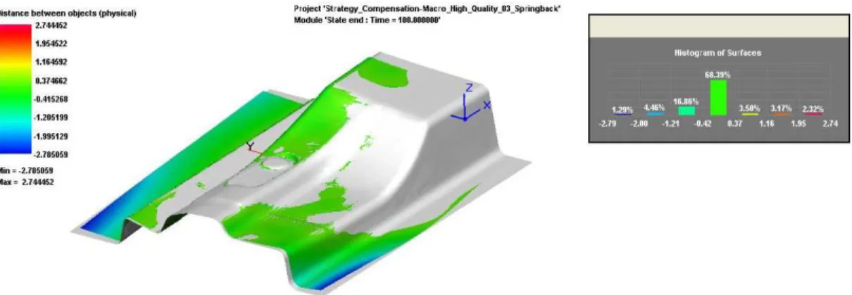
The stamping made from strip steel DX54D has the highest frequency of deviations in terms of springback that within the tolerance are located, while using both mesh strategies. On the contrary the stamping made from strip steel HC220P has the lowest frequency of deviations. In mesh strategy
“Compensation“ is the occurrence of deviations in lower zone of tolerance greatest frequency the stamping made from strip steel HX220YD (see Fig. 8), the stamping made from strip steel HC220P has low frequency of deviation occurrence in lower zone of tolerance.
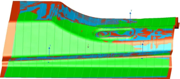
Fig. 8 Analysis „Signed Displacement“ of surface displacement of stamping of internal reinforcement of car bodyshell B-pillar from nominal geometry shape of stamping (drawed grey) using blanks from strip steel HX220YD supplemented frequency histogram of deviations in software
PAM-STAMP 2G 2011 with the chosen mesh strategy “Springback“.
By comparing of both mesh strategies using sections planes was found that at all of materials exist the deviations from nominal geometry of stamping shape and particularly in side walls of stamping and transitional radius between wall and surface flange that springback increases. When using blanks from all strip steels the cross sections from opposite ends of the stamping were turning that is consequence of stress in the stamping. This tension causes torque arising in side of walls of part and both flanges. The curvature of transition edge occurs between straight side of flange to sloping wall on the right side of stamping in the middle (see Fig. 8). The cause of this phenomenon is effect of bending moment in the plane perpendicular to the cross section. Springback occurred as consequence of different ratios towing on the edge and in the middle side wall of stamping. This defect arises in combination with turning of cross section.
5 CONCLUSIONS
At intricate shape stampings with large shape gradients and deep drawing after drawing process the deformation of the walls caused by springback occurs. Springback can by its size after pressing cause that stamping does not keep specified tolerances on the part drawing. For this reason it is important to identify critical areas where is the risk of cracks, because these areas most affect the shape of drawing tool parts. Springback size is strongly influenced by the type of material and geometry of stamping. Design of part geometry and the related design of forming tool should be made such that size of springback will be the least sensitive to change on type of material and other parameters of pressing. Already in the phase of designing of progressive drawing tool it is necessary to correct parts of the drawing tool in such a manner in order to stamping after drawing process remained in fields of tolerances which are specified at the part drawing.
For drawability evaluation of stamping of internal reinforcement of car bodyshell B-pillar the drawing process simulations and the springback size simulations in software PAM-STAMP 2G 2011 for strip steels HX220YD, HX220BD, DX54D and HC220P with mesh strategies “Springback“ and
stamping (see Fig. 3) when using all evaluated strip steels. The minimum thickness of stamping in the critical location is 0.45 mm when using strip steel HX220BD and maximum thickness of the stamping influence thicking of material is 0.74 mm, likewise using strip steel HX220BD. Due to the thickness of stamping 0.65 mm and the size of stamping in drawability analysis is the difference between mesh strategies “Springback“ and “Compensation“ negligible. Differences among mesh strategies showed in significantly strip steel DX54D thinning of the material in analysis over 25 %. In mesh strategy “Springback“ thinning material above 25 % does not occur but mesh strategy
“Compensation“ is material thinning occurs over 25 %. Result of the analysis of stamping thinning indicate how much by percentage the material has thinning or thicking in the drawing process. The limit value for necessity of stamping design changes is 30 % thinning of walls that for solved stamping was not achieved when using any evaluated strip steel. Based on the analysis of stamping drawability of solved stamping can be stated that its geometry conform (Fig. 4) and that by using the mesh strategy “Compensation“more accurate results are achieved.
By springback simulations was found that when using all evaluated strip steels at the stamping of internal reinforcement of car bodyshell B-pillar occurred increase of bended radius of side walls to stamping planar surfaces. Its cause is unequal distribution of stress or stress gradient in the thickness of sheet-metal. Furthermore, the angle cross-section rotation arises which is caused by small torsional stiffness of stamping and also small change in the shape arises which is influenced by springback.
To achieve the minimum size of springback after drawing of stamping of internal reinforcement of car bodyshell B-pillar the use of strip steel HX220YD was evaluated as the most suitable. The results are slightly worse when using strip DX54D, strip steel HC220P is the least appropriate.
Springback values can be reduced by achievement of higher degree of deformation of stamping areas. However, if there is springback of stamping, the problem can be solved by reducing the angle between stamping and tool so that given edge after springback was given to the required tolerances specified in part drawing.
According to the fact that at solved stamping of intricate shape are problems in complying with the tolerances specified at the part drawing, it is necessary to use an additional operation – striking, possibly to use the multiple operation drawing.
REFERENCES
[1] ČůDů, R. Tvářitelnost ocelových plechů: odborná knižní monografie. Lektorovali: L. Pollák a P. Rumíšek. 1. vyd. Ostrava: REPRONIS, 2001. 346 s. ISBN 80-86122-77-8.
[2] ČůDů, R. Tvářitelnost materiálů a nekonvenční metody tváření: Plošná tvářitelnost: návody
do cvičení: skriptum. 1. vyd. Ostrava: VŠB– TU Ostrava, 2002. 148 s. ISBN 80-248-0019-5. [3] ČůDů, R. Plošná tvářitelnost kovových materiálů: skriptum. 1. vyd. Ostrava: VŠB– TU
Ostrava, 1998. 90 s. ISBN 80-7078-577-8.
[4] STUDNIČKů, J. Postupové lisovací nástroje. 1. vyd. Praha: SNTL, 1967. 120 s. (bez ISBN). [5] FOREJT, M. Teorie tváření a nástroje. 1 vyd. Brno: Vysoké učení technické v Brně, 1991.
187 s. ISBN 80-214-0294-6.
[6] EVIN, E., HRIV ÁK, A. a KMEC, J. Získavanie materiálových údajov pre numerickú
simuláciu. In Zborník prednášok 7.medzinárodnej konferencie TECHNOLÓGIA 2001: I. diel. Bratislava: Slovenská technická univerzita vBratislavě, Ň001, s. 281-284. ISBN 80-227-1567-0.
[7] AUDY, J. a EVIN, E. Exploring efficiency of tool coating via deep drawing of cylindrical cups. MM Science Journal [online]. 2008 [cit. 2008-06-20], s. 20-Ňň. Dostupný z: <http://www.mmscience.eu/archives/mmsj_2008_06_audy.pdf>.
[8] EVIN, E., et al. CůE podpora pri navrhovani výroby výliskov. Transfer inovácií [online]. 2006 [cit. 2009-04-24], s. 73-76. Dostupný z:
<http://www.sjf.tuke.sk/transferinovacii/pages/archiv/transfer/9-2006/pdf/73-76.pdf>. [9] ESI Group. PAM-STAMP 2G 2011 User´s Guide. Paris: ESI Group, 2011. 876 s.
[11] ČSN EN 10346 (42 0110) Kontinuálně žárově ponorem povlakované ocelové ploché
výrobky–Technické dodací podmínky.Praha: Český normalizační institut, Ň009. ň0 s.
[12] ČSN EN 10325 (42 0343) Ocel –Stanovení přírůstků výrazné meze kluzu vyvolaného tepelným zpracováním (index Bake-Hardening).Praha: Český normalizační institut, Ň007. 8 s. [13] ČSN EN 10268 (42 0946) Ploché výrobky z ocelí svyšší mezí kluzu válcované za studena
k tváření za studena–Technické dodací podmínky. Praha: Český normalizační institut, 2007. 16 s.
[14] ČSN EN 10131 (42 6314)Ploché výrobky bez povlaku a elektrolyticky pokovené zinkem nebo
kombinací zinek-nikl z nízkouhlíkové oceli a zocelí svyšší mezí kluzu ktváření za studena– Mezní úchylky rozměrů a tolerance tvaru.Praha: Český normalizační institut, Ň006. 16 s. Results in the contribution were achieved at solving of specific research project No. SP2012/162 with the name ”Optimization of Flat and Volume Forming Processes with the Use of Physical Simulation and Finite Element Method” („Optimalizace procesů plošného a objemového