Materials Research, Vol. 9, No. 1, 73-76, 2006 © 2006
*e-mail: [email protected], [email protected]
Computer Simulation of Stress Distribution During
Vickers Hardness Testing of WC-6Co
Avelino Manuel da Silva Diasa*, Paulo José Modenesib*, Geralda Cristina de Godoyb
a
Mechanical Engineering Department, Federal University of São João Del-Rei – UFSJ,
Frei Orlando Square, 170,
36307-384
São João Del-Rei - MG
b
Metallurgical and Materials Engineering Department,
Federal University of Minas Gerais – UFMG
Received: December 2, 2004; Revised: October 11, 2005
This paper describes a numerical simulation and experimental study of the Vickers indentation testing of WC-6Co specimens. The numerical analysis was implemented by a three-dimensional finite element (FE) model using the commercial solver MARC™. Hardness values predicted by this model agreed well with those obtained experimentally. It was also observed that the load-displacement curves obtained numerically were quite similar to those presented by the literature for the Vickers testing. The maximum principal stress field was used to locate the most expected areas for crack formation and propagation during the Vickers indentation testing of WC-6Co.
Keywords: indentation testing, vickers hardness, fracture and numerical analysis
1. Introduction
Indentation testing is commonly used for surface hardness meas-urement of different materials1. This testing method is, however, quite versatile and several new applications for it have been proposed. These include the evaluation of different mechanical properties of materials including elasticity modulus (E), fracture toughness (KIC),
and the elastic-plastic power law curve2.
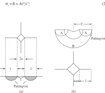
However, the implementation of some of these techniques and many of their results still raise questions among researchers3,4. Dif-ficulties are particularly acute when materials like tungsten carbide with cobalt (WC-Co), which present a mechanical behavior between a plain brittle ceramic and a more ductile metal, are tested5. WC-Co is a material frequently used to manufacture cutting tools for which very high surface hardness and compression and wear strength are expected6. These peculiar mechanical properties make it difficult to evaluate those materials through conventional testing techniques. Consequently, several non-conventional techniques have been proposed in the literature to evaluate the mechanical properties of WC-Co7,8. Among these, the Vickers indentation testing is one of the most used to evaluate fracture toughness of tungsten carbide and similar materials. However, this application of Vickers testing presents some limitations or drawbacks. Amongst these limitations, the diversity of empirical equations that are available to calculate fracture toughness based on two main models of crack nucleation and propagation is one of the most important, Figure 1. During the Vickers indentation testing of WC-Co, the surface radial cracks that usually can be observed are considered to be Palmqvist cracks9.
Numerical modeling can contribute to solve some of the limitations of the experimental analysis of Vickers indentation testing. Such ap-proach can estimate the strain and stress fields in the material around the indentation, helping to sort out areas with more favorable conditions for crack nucleation and propagation during the test, and, allowing a more thorough understanding of the test. In the last ten years, some attempts to numerically model by finite element analysis indentation testing of different materials have been performed10-13. However, even this approach has presented some shortcomings related to several fac-tors including the need of higher computer performance and the lack of adequate criteria to characterize crack nucleation and propagation.
This work presents a numerical simulation of Vickers testing of tungsten carbide with 6% cobalt (WC-6Co) using finite element three-dimensional models. This work was coupled with the experi-mental determination of Vickers hardness and fracture toughness of a WC-6Co machining insert by indentation techniques. The numerical approach was trigged by the difficulties to experimentally evaluate stress and strain fields developed in the material during the loading and unloading cycles of an indentation test. In this paper, the stress fields obtained by numerical simulation, the predicted sites for cracking nucleation, the predicted load evolution during testing and predicted hardness values are compared with the experimental data and also with results reported in the literature.
2. Methodology
2.1. Hardness testing
The experimental hardness testing of WC-6Co inserts was performed in a Heckert hardness testing machine using a 136° pyramidal diamond indenter. The procedure was in accordance to the DIN50133 standard14. Before indentation, the insert surface was polished to a mirror-like finishing in order to minimize the presence of residual stresses. This procedure included an initial grinding step with silicon carbide emery paper and a final polishing step with aluminum oxide (0.1 µm)15. Two load levels (294 N and 612.5 N) were used. The load was slowly applied to the insert surface by the indenter with a penetration speed of about 0.001-0.02 mm/s dur-ing 30 seconds. After this time, the indenter was removed from the specimen surface and the indentation dimensions were measured with an optical microscope1. The results from these tests were used as part of the validation process of the numerical model developed in this work. They were also used to define values to some input variables of the model.
Fracture toughness was evaluated from the indentation test results by the semi-empirical equation for Palmqvist cracks proposed by Niihara9 and modified by Szutkowska8, Equation 1.
74 Dias et al. Materials Research
Where KIC is the fracture toughness, H is the hardness, E is the
elasticity modulus, a is the half length of the indentation diagonal, l is the half size of the Palmqvist surface crack, Figure 1, and φ is a
restriction factor proposed by Szutkowska8. According to Niihara9 and Szutkowska8, this equation is one of the most reliable to evaluate fracture toughness of tungsten carbide with cobalt.
2.2. Numerical modeling
The numerical simulations were developed with the commercial finite element software MARC™ 16. This software is considered to be very efficient to perform numerical analysis of systems that are characterized by high strain and stress gradients and a non-linear behavior.
Hardness values obtained by Vickers testing do not usually depend of the load that was used. This feature allows simulating the indentation cycle of the test by imposing displacements to the indenter, an approach that tends to present a better stability17. A similar approach was adopt to simulate the removal of the indenter from the specimen. In the present work, displacement steps of 0.02 mm were adopted based on results of the experimental tests13,16. The loading and unloading cycles were modeled using 800 and 200 interaction steps, respectively.
To reduce the processing time, only a quarter of both the WC-6Co specimen and the indenter were considered in the model, Figure 2. The specimen was modeled as a circular plate using three-dimensional 20-nodes brick elements that were arranged in a mesh with 3000 elements and 13261 nodes, Figure 2. The bottom of the plate was constrained in the indentation direction (z-axis). Other boundary conditions linked to the problem symmetry were applied to speci-men planes in the x and y directions17,18. The Vickers indenter was modeled as a rigid plate forming a pyramid with an angle of 136° between its opposing faces.
The WC-6Co specimen was considered as an isotropic, homo-geneous material with Young modulus of 619.5 MPa, and Poisson coefficient of 0.282,17. The elastic-plastic behavior of this material was represented by Equation 2 where σe is the effective stress, εe is the effective strain, ε’e the effective strain rate, m is the hardening coef-ficient and n is the strain rate sensitivity coefcoef-ficient. Table 1 presents values of A, B, n, m, yield stress (σy), transversal rupture stress (σTR),
and fracture toughness (KIC) that were adopted in the present work
based on data from the literature for WC-6Co2,6.
σe=B + Aε m
eε’ n
e (2)
Table 3. Fracture toughness of WC-6Co calculated from the indentation
testing results.
Hardness (GPa) φ= H/σy l/a KIC (MN/m3/2)
17.66 3.07 1.27 9.68
18.03 3.13 0.75 10.10
l l
2a
Palmqvist
(a) (b)
a l
A A
B C
Palmqvist
Figure 1. Models of crack nucleation and growth during Vickers indentation
testing: a) Niihara9; and b) Laugier5.
Table 1. Mechanical properties of WC-6Co2,6.
σy (MPa) σTR (MPa) A (MPa) B n m KIC (MN/m 3/2)
5760 3750 18060 0 0 0.244 10.0
Table 2. Example of experimental results obtained in the hardness testing
of WC-6Co17. Load
(N)
Hardness (GPa)
Diagonal length (2a)
Mean crack length (l)
l/a ratio
612.5 17.66 139.3 µm 88.6 µm 1.27
294.0 18.03 89.6 µm 33.8 µm 0.75
Z
Y X
Figure 2. Numerical representation of the WC-6Co specimen and indenter.
3. Results and Discussion
Table 2 shows results obtained in the experimental hardness test-ing of WC-6Co. It can be observed that, as expected, hardness values obtained with the two load levels are quite close. Figure 3 shows an indentation on the WC-6Co surface where characteristic radial cracks can be observed. The ratio between the crack and indenta-tion diagonal lengths was inside the 0.25-2.5 range that characterize Palmqvist radial cracks2,3,9.
Fracture toughness (KIC) of WC-6Co was evaluated from the
results presented in Table 2 using Equation 1. In this calculation, it was also used data from Table 1 and the restrain factor (φ) sug-gested by Szutkowska8. Table 3 shows the values of K
Vol. 9, No 1, 2006 Computer Simulation of Stress Distribution During Vickers Hardness Testing of WC-6Co 75
obtained. When these results are compared to that presented by Trent6, 10 MN/m3/2, for the fracture toughness of WC-6Co (measured by flexion testing), a difference of less than 10% is obtained.
The numerical simulation of the Vickers testing of WC-6Co ob-tained a surface hardness value of 18.63 GPa. This value was about 4% higher than the measured ones and indicates that the simulation represented adequately the global behavior of the Vickers indenta-tion testing. Figure 4 presents the load-displacement relaindenta-tionship predicted by the model for the test cycle (loading and unloading). This relationship is quite similar to those found in the literature for the indentation testing of different materials of low-toughness2,12,18. It can be observed in Figure 4 that the unloading path differs remarkably from the loading path what results in a residual displacement after the testing load drops to zero. This displacement is the indentation depth and is associated to the plastic deformation that occurs in the material around the indentation. The localized plastic deformation creates a residual stress field that is a the key factor for the nucleation and propagation of cracks during the unloading period of the test.
Figure 5 shows the distribution of the maximum principal stress predicted by the model by the end of the test in the plane that includes the indentation diagonal. This stress field was used in conjunction with Rankine criterion, Equation 3, to predict regions in this plane where crack nucleation was expected17.
σ1≥σTR (3)
Strong levels of residual tensile stresses are observed close to the specimen surface and the indentation tip. This agrees well with results from both experimental tests and numerical simulations found in the literature that usually indicate the nucleation of cracks close to the indentation tip5,8,9,18. On the other hand, a region of compres-sion stresses is observed under the indentation. Crack nucleation and propagation are not expected in this region9.
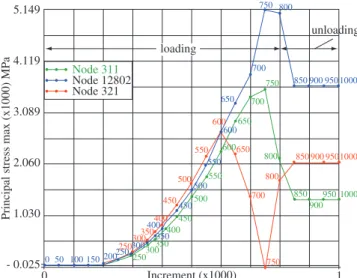
Three points (nodes 321, 12802 and 311, Figure 5) in the region close to the indentation tip were selected to show the stress evolution during the simulation, Figure 6. A build up of high levels of tensile stresses is observed by the end of the loading cycle e during unload-ing. Therefore, considering Rankine criterion and the value of σTR of WC-6Co (Table 1) a high chance of cracking can be expected in this region. The location of tensile of compression stress fields also suggests the formation of Palmqvist type cracks, Figure 1, close to the indention tips.
Figure 3. Indentation with radial surface cracks.
780 760
740 720
700 680 660
640
- 0.052 4.616
Load (x10)N
- 2 Displacement (x 0.01) mm 0
620 600
580 560
540 520
500 480
460 440
420 400
380 360
340 320
300 280
260 240
220 200
180 160
140 8060 201000
120
840 860 880 900 920 940
960 980
800
40 100
Figure 4. Simulated loading and unloading cycles.
1.639e + 004
1.031e + 004
4.231e + 003
- 1.848e + 003
- 7.927e + 003
- 1.401e + 004
- 2.009e + 004
- 2.616e + 004
- 3.224e + 004
- 3.832e + 004 Z
Y
X Principal stress max MPa
node 12802 node 321 node 311
tension Inc: 1000 Time: 1.000e + 000
compression
Figure 5. Distribution of the highest principal stress in the plane that contains
the indentation diagonal.
Principal stress max (x1000) MP
a
5.149
4.119
3.089
2.060
1.030
- 0.025
Increment (x1000) 1
0
unloading
loading
750 850 900 950 1000 700
650
800 850 900 9501000
700 800 650
750 600
550
500
850 900
950 1000 700
650
600
550
500
450 400 350
350
250
0 50 100 150 200250 300300300
350 250
400 450
500 550
600
450
400
750 800
Node 321 Node 311 Node 12802
Figure 6. Evolution of the highest principal stress during the simulation of
76 Dias et al. Materials Research
The main point of the present work is related to the numerical simulation of Vickers testing of a quasi-brittle material. Its results strongly suggest that radials cracks should nucleate and growth close to indentation tips. This is in agreement with experimental results from the literature that show that the radial cracks formed during indentation testing of WC-6Co is of the Palmqvist type.
4. Conclusions
This work presents experimental and numerical results of indenta-tion testing of tungsten carbide with 6% cobalt. Fracture toughness of this material was evaluated experimentally by the indentation testing using a semi-empirical equation. Hardness fracture toughness values agreed well to those reported by Szutkowska8.
The 3D finite element (FE) model developed in the present work was able to represent adequately the general behavior of the Vickers indentation testing and also some qualitative aspects of the stress field around the indentation. The formation of a residual stress field was shown. Predicted maximum principal stress values closed to the indentation in the region around its diagonal direction were higher than the rupture stress of WC-6Co and support the formation of Palmqvist cracks in this region.
As a future work, it is intended to evaluate the condition for crack propagation during indentation testing of WC-6%Co using fracture toughness (KIC) is a failure criterion.
Acknowledgments
This research work was supported by FAPEMIG (Foundation for the Support of Research in the State of Minas Gerais). One of the au-thors would like to thank CAPES/PICDT for the financial support.
References
1. Souza SA. Ensaios Mecânicos de Materiais Metálicos: Fundamentos teóricos e práticos. 5th ed. Brasil: Ed. Edgard Blücher LTD; 2000.
2. Zeng K, Chiu C-h. An analysis of load-penetration curves from instru-mented indentation. Acta Materialia. 2001; 49. p. 3539.
3. Ponton CB, Rawlings RD. Vickers indentation fracture toughness test, Part1. Materials Science and Technology. 1989; 5. p. 871.
4. Schubert WD, Neumeister H, Kinger G, Lux B. Hardness to toughness relationship of fine-grained WC-Co hardmetals. International Journal of Refractory Metals & Hard Materials. 1998; 16. p. 135.
5. Laugier MT. Palmqvist crack extension and the center-loaded penny crack analogy. Journal of American Ceramic Society. 1985; 68(2):51-52. 6. Trent EM. Metal Cutting. 2nd Edition. Butterworths & Co. LTD; 1984.
7. Densley JM, Hirth JP. Fracture toughness of a nanoscale WC-Co tool steel. Scripta Materialia. 1998; 38(2):239-244.
8. Szutkowska M. Fracture toughness measurement of WC-Co hardmetals by indentation method. Journal of Advanced Materials. 1999; 31(3):3-7. 9. Niihara K. A Fracture mechanics analysis of indentation-induced
palmqvist crack in ceramics. Journal of the Materials Science Letters. 1983; 2(5):221-223.
10. Laursen TA, Simo JCA. Study of the mechanics of microindentation using finite elements. Journal of Materials Research. 1992; 7(3):618-626.
11. Marx V, Balke HA. Critical investigation of the unloading behaviour of sharp indentation. Acta Materialia. 1997; 45(9):3791-3800.
12. Niezgoda T, Matachowski J, Boniecki M. Finite element simulation of vickers microindentation on alumina ceramics. Ceramics International.
1998; 24(5):359-364.
13. Dias AMS, Modenesi PJ, Godoy GC, Cetlin PR. Simulação numérica do ciclo de indentação em uma amostra de WC-6Co. Proceedings of XXIV Iberian Latin-American Congress on Computational Methods in Engineering; 2003 Oct 29-31; Ouro Preto-MG, Brasil [CD-ROM].
14. Msc.MARC. Theory and User Information. Volume A. Users Manual;
2001. Available from: http://www.mscsoftware.com/support.
15. Deutschen Normen DIN 50133. Testing of Metallic Materials - Vickers Hardness Testing. Berlim; 1972. Available from: http://www.normung. din.de.
16. Dias AMS. Análise Numérica do Processo de Fratura no Ensaio de Inden-tação Vickers em uma Liga de Carboneto de Tungstênio com Cobalto. [D.
Thesis on Internet] Belo Horizonte: Federal University of Minas Gerais; 2004.
17. Dias AMS, Modenesi PJ, Godoy GC, Ávila RF. Análise do Ensaio de Indentação Vickers em uma Pastilha de WC-Co. Proceedings of XVI Brazilian Congress of Engineering and Materials Science; 2004 Dec 2-6; Porto Alegre-RS, Brasil [CD-ROM].