Brazilian Journal of Physics, vol. 40, no. 3, September, 2010 327
Study of the Parameters Affecting Ion Beam Emerging from Cold Conical Cathode Ion Source
H. El-Khabeary
Accelerators & Ion Sources Department, Basic Nuclear Science Division, Nuclear Research Center, Atomic Energy Authority, P.N.13759, Egypt.
(Received on 6 March, 2010)
The aim of this work is study of the parameters affecting ion beam emerging from cold conical cathode ion source. The input discharge and output ion beam characteristics have been measured at different pressures using nitrogen and argon gases. The optimum distance between the ion exit aperture of the cathode and the movable copper ion collector plate has been determined using nitrogen and argon gases. The ion collector plate has been placed at different distances from the ion exit aperture of the cathode equal to 2, 3, 4, 4.5, 5, 5.5 and 6 cm respectively. It is found that the optimum distance between the ion exit aperture of the cathode and the ion collector plate equals 5 cm for high output ion beam current. At this optimum distance, the efficiency of the ion source reaches 28.3% and 21.3% using nitrogen and argon gases respectively. The divergence angle of the ion beam exit from the cathode aperture has been determined for each distance by measuring the ion beam diameter which obtained on the ion collector plate. It is found that at the optimum distance between the ion exit aperture of the cathode and the ion collector plate, a minimum divergence angle of the ion beam emerging from the ion source equal to 1.140and 2.290using nitrogen and argon gases respectively. Also the aspect ratio of the ion source, the ratio between the radius of the ion exit aperture of the cathode to the distance between the ion exit aperture of the cathode and ion collector plate, has been determined.
Keywords: Cold Conical Cathode Ion Source, Divergence Angle, Aspect Ratio
INTRODUCTION
An ion source is defined as a device in which the gas ions are produced, focused [1], accelerated and emitted as a nar-row intense beam [2]. The ion source is the important single element in an ion beam system. The characteristics of the ion source determine to a great extent the performance of the entire system.
In all types of ion sources [3], the ions are produced by an electrical discharge [4] through a gas or vapor of liquid or solid at low pressure. The ionization is produced by electron impact in gaseous discharge. The general requirements are a source of electrons, a small region of relatively high gas pres-sure, an electric field to accelerate the electrons in order to produce intense gas discharge, plasma, with relatively high electrons and ions density and some mechanism for extract-ing a collimated parallel high current ion beam. The high pressure discharge region is ended by an electrode, cathode, with small exit hole for output ion beam current. The ad-justable parameters of an ion source are electron emission, gas pressure, voltage across the discharge, magnetic field, distance between the electrodes, size of the exit hole, geom-etry and surface properties of the electrodes and the dimen-sions of the discharge vessel.
The emerging ion beam from any ion source [5] is diver-gent due to the aperture effect. However, some emerdiver-gent ions while going through the aperture hit its sides and are then lost causing the reduction of the ion source efficiency. The diver-gence in the ion beam is undesirable in many applications because it forces the user to place his specimen very close to the source. This may cause damage to the specimen due to the thermal radiation from the source. In ion thinning of specimens for electron microscopy, a well directed beam of high intensity is required. In particle accelerator [6] applica-tions, it is necessary to use an ion beam with low divergence angle, so that the beam emittance is lower than the accelera-tor acceptance, otherwise the acceleraaccelera-tor tends to reject some part of the beam. Therefore the production of high ion beam
current with low divergence angle has many advantages for various applications.
In recent years, there has been a rapid growth in the uti-lization of ion sources for a variety of applications, includ-ing nuclear physics, isotopes separators, multiampere beams for fusion applications and for industrial production appli-cations. Also they are useful tools in ion implantation, ion sputtering [7], ion etching, ion beam machining, ion beam surface modification [8] and neutron generators. As a con-sequence of this growth, there has been the need for a better understanding of the factors which affect the optical qual-ity [9] of ion beams.
DESCRIPTION OF THE ION SOURCE
328 H. El-Khabeary
collector plate is connected to earth through micro-ampere meter to measure the ion beam current emerge from central aperture of the cathode.
FIG. 1: Cold conical cathode ion source and its associated electrical circuit.
EXPERIMENTAL RESULTS
In this work, all the experimental results are investigated at the optimum gap distance between the anode and the cath-ode, dA−C =10 mm, with optimum inner diameter of two
confinement rings equal to 7 mm which have been obtained before [10]. The input discharge and output ion beam char-acteristics of the ion source are measured using nitrogen and argon gases. Also the parameters which affect ion beam emerge from the ion source such as the distance between the ion exit aperture of the cathode and the ion collector plate and the ion source aspect ratio are determined.
1 – Input discharge characteristics using nitrogen and argon gases
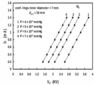
Figures (2-3) show the relation between discharge current, Id, and discharge voltage,Vd, fordA−C=10 mm with
op-timum inner diameter of two confinement rings at different pressures, P, using nitrogen and argon gases. It is clear that an increase of the discharge voltage was accompanied by an increase of the discharge current, where at the same dis-charge voltage; the disdis-charge current is higher at high pres-sure than that at low prespres-sure. Also at the same operating conditions such as discharge current and pressure, the dis-charge voltage in case of nitrogen gas start at low value than that in case of argon gas. This is due to the higher ionization potential of argon gas than that of nitrogen gas.
2 - Output ion beam characteristics using nitrogen and argon gases
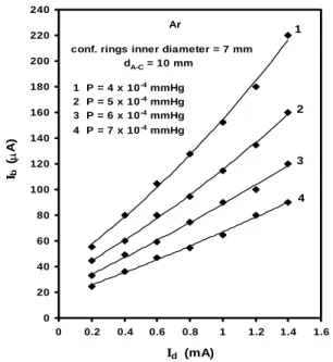
Figures (4–5) show the relation between the output ion beam current,Ib, and the discharge current,Id, fordA−C=10
0 0.2 0.4 0.6 0.8 1 1.2 1.4 1.6 1.8
0 0.4 0.8 1.2 1.6 2 2.4 2.8 3.2 3.6 4
Vd (KV)
I
d
(m
A
)
conf. rings inner diameter = 7 mm
dA-C = 10 mm
1 P = 4 x 10⁻⁴ mmHg 2 P = 5 x 10⁻⁴ mmHg 3 P = 6 x 10⁻⁴ mmHg 4 P = 7 x 10⁻⁴ mmHg
N2
1 2 3 4
FIG. 2: Discharge current versus discharge voltage atdA−C=10mm for two confinement rings of inner diameter equal to 7 mm using nitrogen gas.
0 0.2 0.4 0.6 0.8 1 1.2 1.4 1.6 1.8
0 0.4 0.8 1.2 1.6 2 2.4 2.8 3.2 3.6 4 4.4 4.8
Vd (KV)
I
d
(m
A
)
conf. rings inner diameter = 7 mm
dA-C = 10 mm
1 P = 4 x 10⁻⁴ mmHg 2 P = 5 x 10⁻⁴ mmHg 3 P = 6 x 10⁻⁴ mmHg 4 P = 7 x 10⁻⁴ mmHg
Ar
1 2 3 4
FIG. 3: Discharge current versus discharge voltage atdA−C=10mm for two confinement rings of inner diameter equal to 7 mm using argon gas.
mm with optimum inner diameter of two confinement rings, the distance between the ion exit aperture of the cathode and the ion collector plate,dC−CP, equals 4 cm and at different pressures using nitrogen and argon gases. It is clear from the curves that the output ion beam current increases by in-creasing the discharge current and atP=4×10⁻⁴ mmHg andId=1.4 mA, a maximum output ion beam current reach
Brazilian Journal of Physics, vol. 40, no. 3, September, 2010 329
0 20 40 60 80 100 120 140 160 180 200 220 240 260 280 300 320 340 360
0 0.2 0.4 0.6 0.8 1 1.2 1.4 1.6
Id (mA) Ib
(µ
A)
N2
1 P = 4 x 10⁻⁴ mmHg
2 P = 5 x 10⁻⁴ mmHg
3 P = 6 x 10⁻⁴ mmHg
4 P = 7 x 10⁻⁴ mmHg
1
2
3
conf. rings inner diameter = 7 mm dA-C = 10 mm
4
FIG. 4: Output ion beam current versus discharge current for dA−C=10 mm with two confinement rings of inner diameter equal to 7 mm at different pressures using nitrogen gas.
0 20 40 60 80 100 120 140 160 180 200 220 240
0 0.2 0.4 0.6 0.8 1 1.2 1.4 1.6
Id (mA)
I (b
µ
A)
1 P = 4 x 10⁻⁴ mmHg
2 P = 5 x 10⁻⁴ mmHg
3 P = 6 x 10⁻⁴ mmHg
4 P = 7 x 10⁻⁴ mmHg
conf. rings inner diameter = 7 mm dA-C = 10 mm
Ar 1
2
3
4
FIG. 5: Output ion beam current versus discharge current for dA−C=10 mm with two confinement rings of inner diameter equal to 7 mm at different pressures using argon gas.
3 - Determination the optimum distance between ion exit aperture of the cathode - ion collector plate and the ion source efficiency
One of the parameter which play an important role in the performance and efficiency of the ion source is adjust the
distance between the ion exit aperture of the cathode and the ion collector plate,dC−C p, for obtaining maximum output ion beam current with small divergence angle. In this work the ion collector plate has been placed at different distances from the ion exit aperture of the cathode equal to 2, 3, 4, 4.5, 5, 5.5 and 6 cm respectively and at each distance the ion beam diameter obtained on the collector plate has been measured.
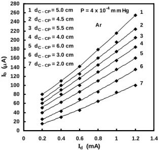
Figures (6 and 7) show the relation between output ion beam current versus discharge current at constant pressure for different distances between ion exit aperture of the cath-ode and ion collector plate using nitrogen and argon gases. It is clear that the characteristics show a family of straight line relations, where increasing the discharge current leads to increase the output ion beam current. In case of nitrogen gas at constant discharge current equals 1.2 mA, the value of the output ion beam current reach 340µAatdC−CP=5 cm while at dC−CP =2 cm the output ion beam current is
140µA. Also in case of argon gas at constant discharge cur-rent equals 1.2 mA, the value of the output ion beam curcur-rent reach 255 µAatdC−CP =5 cm while at dC−CP =2 cm the
output ion beam current equals 100µA.
0 20 40 60 80 100 120 140 160 180 200 220 240 260 280 300 320 340 360 380
0 0.2 0.4 0.6 0.8 1 1.2 1.4
Id (mA)
Ib
(µ
A)
P = 4 x 10⁻⁴ m m Hg 1 dC - CP= 5.0 cm
2 dC - CP = 4.5 cm
3 dC - CP = 5.5 cm
4 dC - CP = 4.0 cm
5 dC - CP = 6.0 cm
6 dC - CP = 3.0 cm
7 dC - CP = 2.0 cm
N2
1
2 3 4
5
6
7
FIG. 6: Output ion beam current versus discharge current at differ-ent cathode – collector plate distances using nitrogen gas.
Fig. (8) shows output ion beam current,Ib, versusdC−CP, atdA−C =10 mm with two confinement rings of inner di-ameter equals 7 mm, constant pressure and discharge cur-rent using nitrogen and argon gases. It is obvious from the curves that at dC−CP =5 cm, a maximum output ion
beam current can be obtained. While before and after this optimum distance the output ion beam current decreases. Fig. (9) shows the ion source efficiency,Ib/Id, versusdC−CP, atdA−C=10 mm with two confinement rings of inner
diame-ter equals 7 mm, constant pressure and discharge current us-ing nitrogen and argon gases. It is clear that atdC−CP=5 cm,
330 H. El-Khabeary
0 20 40 60 80 100 120 140 160 180 200 220 240 260 280
0 0.2 0.4 0.6 0.8 1 1.2 1.4
Id (mA) Ib
(µ
A)
P = 4 x 10⁻⁴ m m Hg
1 dC - CP= 5.0 cm
2 dC - CP = 4.5 cm
3 dC - CP = 5.5 cm
4 dC - CP = 4.0 cm
5 dC - CP = 6.0 cm
6 dC - CP = 3.0 cm
7 dC - CP = 2.0 cm
Ar
1
2
3 4
5
6
7
FIG. 7: Output ion beam current versus discharge current at different cathode – collector plate distances using argon gas.
0 30 60 90 120 150 180 210 240 270 300 330 360 390
0 1 2 3 4 5 6 7
dC-CP (cm)
Ib
(µ
A)
P = 4 x 10⁻⁴ m m Hg
Ar
Id= 1.2 m A
N2
FIG. 8: Output ion beam current versusdC−CPusing nitrogen and
argon gases.
4 - Determination the ion beam divergence angle
Fig. (10) shows ion beam diameter which has been ob-tained on the collector plate versusdC−CP at constant pres-sure and discharge current using nitrogen and argon gases. From this figure it is clear that the ion beam diameter which obtained on the collector plate has a minimum value at dC−CP=5 cm. While before and after this distance the ion
beam diameter increases.
The divergence angle of the ion beam exit from the cath-
0 5 10 15 20 25 30 35
1 2 3 4 5 6 7
dC-CP (cm )
Io
n
s
o
u
rc
e
e
ff
ic
ie
n
c
y
(
Ib
/
Id
)
℅ P = 4 x 10
-4 mmHg
Id= 1.2 mA dA-C = 10 mm
FIG. 9: Ion source efficiency versusdC−CP using nitrogen
and argon gases.
ode aperture can be calculated using the relation:
θ
2 =
r
ion beam−rcathode dC−CP
(1)
whereθis the ion beam divergence angle,r
ion beam is the radius of the ion beam which has been obtained on the collec-tor plate,rcathode is radius of ion exit aperture of the cathode anddC−CPis the distance between the ion exit aperture of the cathode and the ion collector plate.
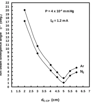
Fig. (11) shows ion beam divergence angle versusdC−CP atdA−C =10 mm with two confinement rings of inner
di-ameter equals 7 mm, constant pressure and discharge current using nitrogen and argon gases. From this figure it is obvious that the ion beam divergence angle decreases by increasing dC−CP and reach a minimum value equals 1.140 and 2.290 for nitrogen and argon gases respectively atdC−CP=5 cm
then stat increases.
5 – Determination the aspect ratio of the ion source
The aspect ratio of the ion source has been determined from the experimental results such as discharge current and output ion beam current at different distances between ion exit aperture of the cathode and ion collector plate using ni-trogen and argon gases.
Fig. (12) shows the relation between output ion beam cur-rent and aspect ratio, S, at constant pressure and discharge current using nitrogen and argon gases. It is clear from the curves that, the maximum value of the output ion beam cur-rent is obtained atS=0.02 and reach 340µAand 255µAfor nitrogen and argon gases respectively. This indicates that the optimumdC−CP=5 cm.
CONCLUSION
Brazilian Journal of Physics, vol. 40, no. 3, September, 2010 331
2 2.5 3 3.5 4 4.5 5 5.5 6 6.5
0 1 2 3 4 5 6 7
dC-CP (cm)
Io
n
b
e
am
d
ia
m
et
e
r o
n
co
ll
e
c
to
r
p
lat
e
(
m
m
) P = 4 x 10⁻⁴ m m Hg
N2
Id= 1.2 m A
Ar
FIG. 10: Ion beam diameter on the collector plate versus distance between the ion exit aperture of the cathode and the ion collector plate using nitrogen and argon gases.
0 1 2 3 4 5 6 7 8 9 10 11 12 13 14 15 16 17 18 19 20 21 22
1 1.5 2 2.5 3 3.5 4 4.5 5 5.5 6 6.5 7
dC-CP (cm)
Ion be
a
m
di
v
e
rge
nc
e
a
ngl
e
θ
o (
d
e
g
.)
P = 4 x 10⁻⁴ m m Hg
Ar Id= 1.2 m A
N2
FIG. 11: Ion beam divergence angle versus the distance between the ion exit aperture of the cathode and the ion collector plate using nitrogen and argon gases.
dC−CP =4 cm, a maximum output ion beam current reach
325µAand 220µAcan be obtained using nitrogen and argon gases. But from the optimum distance curves between ion exit aperture of the cathode and ion collector plate, it is found that atdC−CP=5 cm,P=4×10⁻⁴mmHg andId=1.2mA, a
maximum output ion beam current reach 340µAand 255µA can be obtained using nitrogen and argon gases. The ion source efficiency reached 28.3% and 21.3% using nitrogen and argon gases respectively. Therefore, it can be concluded that a maximum output ion beam current can be obtained at dC−CP =5 cm. Also at this optimum distance, a minimum
value of ion beam divergence angle reach 1.140 and 2.290 can be obtained using nitrogen and argon gases. It can be concluded that a maximum output ion beam current can be obtained atS=.02, i.e atdC−CP=5 cm. Therefore for
expo-sure any specimen to maximum ion beam current with small divergence angle, the specimen must be placed at a distance equals 5 cm from the ion exit aperture of the cathode. This ion source is suitable for ion beam applications such as, sput-tering, etching, material surface modification and microma-chining.
0 20 40 60 80 100 120 140 160 180 200 220 240 260 280 300 320 340 360 380 400
0.012 0.016 0.02 0.024 0.028 0.032 0.036 0.04 0.044
Sٍ
Ib
(µ
A
)
P = 4 x 10⁻⁴ m m Hg Id = 1.2 m A
N2
Ar
FIG. 12: Output ion beam current versus aspect ratio at constant pressure and discharge current using nitrogen and argon gases.
[1] L.A. Giannuzzi and F.A.Stevie; “Introduction to Focused Ion Beams”, Springer, USA (2005).
[2] S.I. Molokovsky and A.D. Sushkov; “Intense Electron and Ion Beams”, Springer, Germany (2005).
[3] B.H. Wolf, “Handbook of Ion Sources”, CRC Press, Boca
Ra-ton, New York (1995).
[4] I.A. Lieberman and L.J. Lichtenberg; “Principles of Plasma Discharges and Materials Processing”, John Wiley & Sons, NJ, USA (2005)
332 H. El-Khabeary
Wiley-VCH Verlag GmbH & Co. KGaA, Weinheim, Germany (2004).
[6] R. Hellborg; “Electrostatic Accelerators”, Springer, Nether-lands (2005).
[7] R. Behrisch and W. Eckstein; “Sputtering by Particle Bom-bardment”, Springer, Berlin (2007).
[8] R.J. Rodrguez, A. Medrano, J.A. Garca, G.G. Fuentes, R. Mart´ınez and J.A. Puertolas; Surface and Coatings
Technol-ogy, 201(19-20), 8146 (2007).
[9] T. Sadahiro, K. Matsuyama, M. Kiuchi, T. Matumoto, T. Tak-izawa, S.Sugimoto, T. Fukuda and S.Goto; Surface and Coat-ings Technology; 188, 265 (2004).