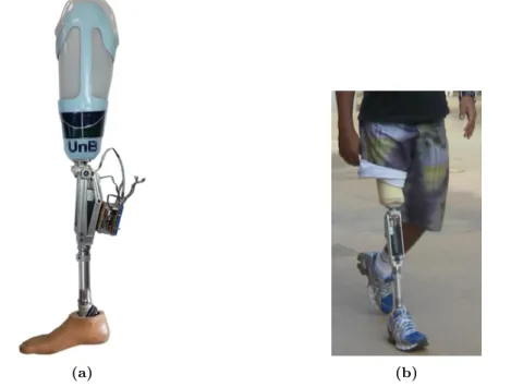
Characterization of amputee gait using a biomechanical approach
Texto
Imagem


Documentos relacionados
Managers involved residents in the process of creating the new image of the city of Porto: It is clear that the participation of a resident designer in Porto gave a
(1984) analisando povoamentos de Eucalyptus saligna, aos 8 e 9 anos de idade, respectivamente, verificaram que em média 85% da biomassa aérea encontrava- se no fuste (madeira
Ousasse apontar algumas hipóteses para a solução desse problema público a partir do exposto dos autores usados como base para fundamentação teórica, da análise dos dados
i) A condutividade da matriz vítrea diminui com o aumento do tempo de tratamento térmico (Fig.. 241 pequena quantidade de cristais existentes na amostra já provoca um efeito
This log must identify the roles of any sub-investigator and the person(s) who will be delegated other study- related tasks; such as CRF/EDC entry. Any changes to
Além disso, o Facebook também disponibiliza várias ferramentas exclusivas como a criação de eventos, de publici- dade, fornece aos seus utilizadores milhares de jogos que podem
didático e resolva as listas de exercícios (disponíveis no Classroom) referentes às obras de Carlos Drummond de Andrade, João Guimarães Rosa, Machado de Assis,
Procuramos, com este trabalho dar um contributo para “uma história social do currículo”, em que o propósito não é apenas descrever como se estruturava a disciplina de
