Evaluation of the prototype of a new
bracket-positioning gauge
Sergio Luiz Mota Júnior1, Marcio José da Silva Campos1, Carina Abrantes Schmitberger2,
Juliana de Andrade Vitral3, Marcelo Reis Fraga1, Robert Willer Farinazzo Vitral1
Objective: The purposes of this study were to present a prototype of a bracket-positioning gauge, which makes vertical inclina-tion of the instrument difficult, allowing a reducinclina-tion of vertical bracket posiinclina-tioning error, and to test its accuracy in bracket posi-tioning by groups of individuals with different clinical experience and in specific groups of teeth. Methods: For the testing of the prototype, four groups of six participants each were used: Group 1 was composed of undergraduate students in the dental school, who had no previous experience in bonding orthodontic attachments; Group 2 was composed of orthodontic graduate students in the dental school; Group 3 consisted of orthodontists with a maximum of 5 years of clinical experience; Group 4 comprised or-thodontists with more than 5 years of clinical experience. A typodont was simulated with a Class I crowded malocclusion, which reproduced the same occlusal characteristics for all groups to be bonded. All participants were instructed to bond 0.022×0.028-in Edgewise brackets on the labial surfaces of the upper and lower incisors, canines, and premolars at a height of 4 mm from the incisal edge or the labial cusp tip. Results: Only the mean value of Group 1 showed statistically significant difference in the comparison with the standard measurement. In the groups of teeth, the difference was significant for the premolar and incisor groups. Con-clusion: Clinical experience interfered with the accuracy of vertical positioning of orthodontic attachments. As for the groups of teeth, premolars, followed by canines and incisors had the closest mean values to the standard measurement.
Keywords: Orthodontics. Orthodontic brackets. Orthodontics, corrective. Patents.
1 Universidade Federal de Juiz de Fora, Departamento de Odontologia Social e
Infantil (Juiz de Fora/MG, Brazil).
2 Universidade Federal de Juiz de Fora, Programa de Pós-graduação em Saúde
(Juiz de Fora/MG, Brazil).
3 Universidade Federal de Juiz de Fora, Curso de Graduação em Arquitetura e
Urbanismo, (Juiz de Fora/MG, Brazil).
» The authors report no commercial, proprietary or financial interest in the products or companies described in this article.
DOI: https://doi.org/10.1590/2177-6709.23.2.068-074.oar
How to cite: Mota Júnior SL, Campos MJS, Schmitberger CA, Vitral JA, Fra-ga MR, Vitral RWF. Evaluation of the prototype of a new bracket-positioning gauge. Dental Press J Orthod. 2018 Mar-Apr;23(2):68-74.
DOI: https://doi.org/10.1590/2177-6709.23.2.068-074.oar
Submitted: September 08, 2017 - Revised and accepted: January 12, 2018
Contact address: Sergio Luiz Mota Júnior
Rua Humaitá 10/303, Juiz de Fora/MG - CEP: 36.016-150 - Brasil E-mail: [email protected]
Objetivos: os objetivos deste estudo foram apresentar um protótipo de posicionador de braquetes ortodônticos que dificulte a inclinação no sentido vertical, possibilitando a redução dos erros de altura no posicionamento desses acessórios; além de testar sua precisão na colagem, realizada por grupos de indivíduos com diferentes tempos de experiência clínica em Ortodontia e em grupos específicos de dentes. Métodos: para os testes do protótipo desenvolvido, quatro grupos de seis participantes foram formados. O Grupo 1 foi composto por alunos do curso de Odontologia sem qualquer prática com colagem em Ortodontia; o Grupo 2, por estudantes em Ortodontia; o Grupo 3, por ortodontistas com menos de cinco anos de experiência clínica; e o Grupo 4, por ortodontistas com mais de cinco anos de experiência clínica em Ortodontia. Em um typodont, foi simulada uma má oclusão Classe I com apinhamento, com as mesmas características para todas as colagens realizadas. Todos os participantes foram instruídos a colar braquetes Edgewise 0,022” x 0,028” na superfície vestibular dos incisivos, caninos e pré-molares superiores e inferiores, na altura de 4mm da borda incisal ou cúspide vestibular. Resultados: somente a média do Grupo 1 apresentou diferença estatisticamente significativa na comparação com a medida padrão. Nos grupos de dentes, a diferença foi significativa para o grupo dos pré-molares e incisivos. Conclusão: o tempo de experiência clínica interferiu na precisão do posicionamento vertical do acessório ortodôntico e, quanto aos grupos de dentes, as médias mais próximas à medida padrão foram dos pré-molares, seguidas pelos caninos e incisivos.
INTRODUCTION
Orthodontic treatment should provide the patient with functional and aesthetic balance between dental,
skeletal and facial structures.1,2 In this process, the
cor-rect positioning of orthodontic brackets is of paramount importance for the orthodontic mechanics and
treat-ment results.3-9 Poorly positioned brackets may result
in poor teeth alignment, torque alterations,10-17 changes
in arch length,18 distortions in bracket prescription,19 as
well as occlusal interferences that can compromise mas-ticatory function.7,10,18
For some authors, brackets should be centered
on the crown of the tooth,3,20 whereas others
recom-mend placing the brackets at specific heights for each
tooth or group of teeth.7,10,13,16,21-25 Bracket
position-ing, however, is influenced by the operator and tooth
morphology.2,26-29
Studies show that gauges used for bracket placement, when used with the wrong inclination, may interfere
with the correct bracket height.9,19,28,29 The Boone
gauge, one of the most used bracket positioning devices, allows inadequate inclination of the instrument when positioning orthodontic attachments, regardless of the
operator’s clinical experience.30
The purposes of this study were to present a pro-totype of a bracket-positioning gauge, which makes undesirable vertical inclination of the instrument more difficult than with other gauges, allowing a re-duction of vertical bracket positioning error; and to test its accuracy in bracket positioning by groups of individuals with different clinical experience and in specific groups of teeth.
MATERIAL AND METHODS
This star-like bracket-positioning gauge was con-ceived at the Universidade Federal de Juiz de Fora, with funding from FAPEMIG. The gauge was machined and assembled at Robtec industry in the city of Diadema, São Paulo, Brazil. It consists of a star-like metal base with four points, which allow the placement of orthodontic attachments at the heights of 3.5mm, 4.0mm, 4.5mm, and 5.0mm (Fig 1). In order to minimize bracket-posi-tioning error caused by incorrect vertical inclination of the instrument, on each point end of the gauge there are two pins stuck on a sliding base that should contact the labial surface of the tooth above and below the bracket.
It has a nickel-titanium coil spring adapted posteriorly Figure 1 - Prototype of bracket-positioning gauge.
to the sliding base, which allows the operator to push the instrument towards the tooth, approaching the cen-tral pin toward the bracket (Fig 2). The measuring point end of the gauge should be positioned in a way that the metal base touches the incisal edge or the labial cusp tip of the tooth until the central pin reaches the bracket slot (Fig 3). After the force ceases, the pins and the sliding base return to their original position (Fig 2).
The methodology used in the present study to as-sess vertical bracket positioning was the same as that
de-scribed in a previous report by Mota Júnior et al.30
In order to test the new gauge, four groups of volun-teers were formed according to their clinical experience in orthodontics (Tab 1).
Comparisons between the groups of teeth were made between incisors, canines, and premolars.
For standardization in assembling a Class I maloc-clusion for bracket placement (Fig 4A), an acetate im-pression tray was fabricated to mount the teeth in a ty-podont (Fig 4B). Teeth were mounted in such a way that the gauge could be used without interference.
Figure 2 - Lateral view of the active point end of the prototype.
Table 1 - Distribution of groups of participants, number of participants, and number of teeth in each group.
Figure 3 - Lateral view of the active point end of the prototype with central pin inserted into bracket slot.
Figure 4 - View of typodont with acetate impression tray (A) and with simulated malocclusion (B).
Group Participants Number of participants Number of teeth
1 Undergraduate students with no clinical experience in orthodontics 6 120
2 Orthodontics graduate students 6 120
3 Orthodontists with a maximum of 5 years of clinical experience 6 120
4 Orthodontists with more tan 5 years of clinical experience 6 120
cusp tip, simulating working clinical conditions. Were also available to the participants: non-surgical procedure gloves, Hollemback carver (CVHL1/29; Hu-Friedy, Chicago, Ill, USA), mouth mirror (M8H; Hu- Friedy), tweezers (DPU17; Hu-Friedy), and bonding twee-zers (678-212; Hu-Friedy). For bonding the brackets, Transbond XT composite resin (3M Unitek, Monro-via, Calif, USA) was used and the bracket was cured with a LED curing light for 5 seconds. Neither acid etching of enamel nor a bonding agent was used because teeth were made of plastic and shear bond strength was not under evaluation.
In order to standardize the photographs, teeth were removed from the typodont and inserted into a device with holes filled with self-polymerized acryl-ic resin (Coldpac Ortho Resin; Yates Motloid, Chi-cago, Ill, USA) (one hole for each tooth), keeping the mesial surface of the tooth parallel to and facing towards the camera lens. A Canon EOS XSi digital camera of 13 megapixel, with a macro lens of 100mm (2756B001; Canon, Oita, Kyushu, Japan), shutter speed of 1/100 and aperture of f/2.8 was positioned with the camera lens 20cm from the object to be
pho-tographed.30 A millimeter ruler (CLR6; Hu-Friedy)
was inserted in the photographed field to determine the real dimensions of the images in the Keynote software for Mac Os (Version 6.1, Keynote for Mac;
Apple, Cupertino, Calif, USA).30
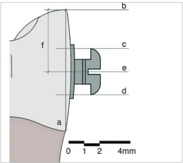
The determination of the representative plane of the labial surface of the teeth (line a, Fig 5) was done with the mesial view using the union of the most an-terior point of the cementoenamel junction and the most incisal point (or labial cusp tip) of the tooth (Fig 5). For the determination of the height of the bonded brackets, the following perpendicular lines to the la-bial plane were traced: tangent line to the most incisal point (or labial cusp tip) (line b, Fig 5), tangent line to the occlusal border of the bracket wings (line c, Fig 5), tangent line to the cervical border of the bracket wings (line d, Fig 5), equidistant line to lines c and d (Fig 5), representing the geometric center of the bracket slot (line e, Fig 5). In order for any possible rotation or inclination of the bracket not to interfere with the measuring of the vertical positioning of the bracket, the most incisal bracket tie wings and the most cervical bracket tie wings were used to deter-mine the geometric center of the bracket.
The bond-ing distance corresponded to the distance between the points in which lines b and e intercepted the rep-resentative plane of the labial face of the tooth
(seg-ment f, Fig 5).30
Statistical analysis
To test the calibration of the evaluator regarding the measurements of the digital images, the error of meth-od was calculated using the intraclass correlation coeffi-cient (ICC), in which all measurements were measured twice with a 30-day interval.
For the statistical analysis the Minitab software for Windows (version 17; Minitab, State College, Pa, USA) was used. The Anderson-Darling test was applied to evaluate the normality of data. For the comparison of the values obtained in each group of participants and for the groups of teeth with the established standard pattern (4mm), the Student’s t-test was performed. Homo-geneity of variances was evaluated using Bartlett’s test with a level of significance of 95%.
RESULTS
The analysis of the calibration procedure showed ex-cellent agreement between evaluations (ICC = 0.995). The sample showed normal distribution (p > 0.05) for the Anderson- Darling normality test.
Table 2 presents the values concerning bonding heights in each group of participants (groups 1-4) and the respective p values (Student’s t test) in comparison with the standard measurement (4mm).
Figure 6 shows the results of Bartlett’s test, indi-cating that at least one group of participants showed
Group n Mean Standard deviation Variance Minimum Maximum p value
1 120 3.737 0.359 0.129 3.037 4.683 <0.05*
2 120 3.996 0.312 0.097 3.376 4.936 0.900
3 120 3.995 0.303 0.092 2.987 4.743 0.882
4 120 4.039 0.267 0.071 3.026 4.868 0.106
Table 2 - Means, standard deviations, variances, minimum, maximum and p value for each group of participants.
* Statistically significant difference.
Table 3 - Means, standard deviations, variances, minimum, maximum and p value for each group of teeth.
* Statistically significant difference.
Group of teeth n Mean Standard deviation Variance Minimum Maximum p value
Incisors 192 3.877 0.308 0.095 3.026 4.743 <0.05*
Canines 96 4.060 0.312 0.098 3.205 4.743 0.061
Premolars 192 3.948 0.352 0.125 2.987 4.936 <0.05*
statistically significant difference when compared to
the homogeneity of variance (p = 0.014) of the four
groups under study.
Table 3 shows the values of the bonding heights of each group of teeth (incisors, canines, and premolars) and the respective p values (Student’s t test) in compari-son with the standard measurement (4mm).
Figure 7 demonstrates the results of Bartlett’s test, indicating that there was no statistically significant dif-ference in the comparison of homogeneity of variances
in the groups of teeth (p = 0.130).
Figure 6 - Bartlett’s test to evaluate the homogeneity between the variances in groups 1, 2, 3 and 4.
DISCUSSION
During installation of orthodontic appliance, it is desirable that the brackets be placed in specific positions
on the surface of the tooth. Visual acuity26,28 as well as
bracket-positioning gauges4-8,27,30 may fail to position
orthodontic attachments vertically. The most often used bracket-positionig gauges are the star-like gauge (also known as Boone gauge) and the pole-like gauge (also
known as height bracket-positioning gauge).19 In case
orthodontic attachments are not properly positioned on the surface of the tooth, compensations in the archwire or replacement of orthodontic attachments will be re-quired,16 increasing chair and treatment time.10,12-14,16-18
In order to minimize the errors on the vertical posi-tioning of the brackets caused by the malposition of the gauge, a prototype bracket-positioning gauge, whose main characteristic is to make it difficult for the operator to incline the instrument during its use, was developed. By positioning the upper and lower end points of the star-like stainless steel bracket-positioning gauge on the surface of the tooth, it allows its central end point to be inserted into the bracket’s slot in a perpendicular way to the labial surface of the tooth. The prototype was manufactured with a thicker base than that of the initial project because of the machining process used.
According to Armstrong et al,28 one should use the
distance from the incisal edge (or labial cusp tip) of the tooth to the center of the bracket as reference for bonding height. By using this reference measurement during the prototype test, only group 1 showed
statisti-cally significant difference (p < 0.05) in the comparison
of the mean (3.737 mm) with the standard measure-ment (4 mm). Groups 2, 3, and 4 showed means with
no significant differences (p > 0.05) when compared to
the standard measurement: 3.996 mm, 3.995 mm, and 4.039 mm, respectively. When comparing these results with those from tests using similar methodology with
the Boone gauge,30 it can be noted that, in all groups
of participants, bracket placement with the prototype presented results closer to the standard measurement of 4 mm, except the group consisted of undergraduate stu-dents with no previous experience in bonding brackets. Besides, this group showed significant greater variance
than the other groups (p < 0.05) in both studies.
For those subjects with experience in bonding or-thodontic attachments (groups 2, 3 and 4), the val-ues of the means did not reveal any relationship with
bonding accuracy and clinical experience. Regardless of the clinical experience in Orthodontics, the mean of bonding height was very close to the standard mea-surement, with no significant differences. Armstrong
et al29 compared the accuracy of bracket placement
by orthodontists and inexperienced dental students and concluded that the vertical accuracy of bracket placement was not related to clinical experience. Mota
Júnior et al,30 in turn, evaluating four groups of subjects
with different clinical experience in bonding brackets, drew the same conclusion.
However, in this type of evaluation the variance in
each group seems to be more important than the mean.30
The use of this prototype yielded smaller variances in Groups 1, 3, and 4 in comparison with the results from the study with the Boone gauge using similar
method-ology.30 As for clinical experience, the prototype study
showed that the longer the clinical experience, the low-er the variance in the groups. In the assessment of ho-mogeneity of variances between the groups of subjects, the Bartlett’s test demonstrated that there was statistical-ly significant difference (p < 0.05) for Group 1 in relation to the other groups. Despite the fact that no participant in the sample had previous experience with the instru-ment, clinical experience, associated with the character-istics of the instrument itself, seems to have influenced the better vertical accuracy of bracket placement.
The evaluation of the groups of teeth showed that premolars had the closest means to 4mm, followed by canines and incisors. Despite that, the difference was significant for the groups of premolars and incisors. Al-though the incisors showed the most distant means to the standard measurement, they showed smaller vari-ance (0.095). For all groups of teeth, the varivari-ances found in the present study were smaller than those found by
Mota Júnior et al:30 0.115, 0.109, and 0.135, for the
inci-sors, canines, and premolars, respectively.
CONCLUSION
The prototype demonstrated vertical accuracy for bonding orthodontic brackets.
Clinical experience interfered with vertical accuracy of bracket placement.
1. Jarabak JR. Development of a treatment plan in the light of one´s concept of treatment objectives. Am J Orthod. 1960 July;46(7):481-514.
2. Mestriner MA, Enoki C, Mucha JN. Normal torque of the buccal surface of mandibular teeth and its relationship with bracket positioning: a study in normal occlusion. Braz Dent J. 2006;17(2):155-60.
3. Andrews LF. The straight-wire appliance, origin, controversy, commentary. J Clin Orthod. 1976 Feb;10(2):99-114.
4. Droschl H, Bantleon HP. Bracket positioning gauge. J Clin Orthod. 1986 Apr;20(4):266-8.
5. Diamond M. Precision bracket placement instrument. J Clin Orthod. 1989 Aug;23(8):556-9.
6. Samuels RH. A new bracket-positioning instrument. J Clin Orthod. 2000 Aug;34(8):482-3.
7. Carlson SK, Johnson E. Bracket positioning and resets: five steps to align crowns and roots consistently. Am J Orthod Dentofacial Orthop. 2001 Jan;119(1)76-80. 8. Geron S. A new instrument for controlled bracket positioning. J Clin Orthod.
2002 Apr;36(4)206-7.
9. Ousehal L, Lazrak L. The accuracy of brackets placement in direct bonding technique: a comparison between the pole-like bracket positioning gauge and the star-like positioning bracket gauge. OJST. 2011 Dec;1(4):121-5.
10. McLaughlin RP, Bennett JC. Bracket placement with the preadjusted appliance. J Clin Orthod. 1995 May;29(5)302-11.
11. Meyer M, Nelson G. Preadjusted edgewise appliances: theory and practice. Am J Orthod. 1978 May;73(5)485-98.
REFERENCES
12. Thurow RC. Edgewise orthodontics. St Louis: Mosby; 1962.
13. Alexander RG. The vari-simplex discipline. Part 1. Concept and appliance design. J Clin Orthod. 1983 June;17(6):380-92.
14. Germane N, Bentley BE, Isaacson RJ. Three biologic variables modifying faciolingual tooth angulation by straight-wire appliances. Am J Orthod Dentofacial Orthop. 1989 Oct;96(4):312-9.
15. Germane N, Bentley BE, Isaacson RJ, Revere, JH. The morphology of canines in relation to preadjusted appliances. Angle Orthod. 1990 Spring;60(1):49-54. 16. Balut N, Klapper L, Sandrik J, Bowman D. Variations in bracket placement in
the preadjusted orthodontic appliance. Am J Orthod Dentofacial Orthop. 1992 July;102(1):62-7.
17. Creekmore TD, Kunik RL. Straight wire: the next generation. Am J Orthod Dentofacial Orthop. 1993 July;104(1):8-20.
18. Hussels W, Nanda RS. Effect of maxillary incisor angulation and inclination on arch length. Am J Orthod Dentofacial Orthop. 1987 Mar;91(3):233-9. 19. Mohammadi A, Moslemzadeh SH. Comparison of the accuracy of bracket
placement with height bracket positioning gauge and Boone gauge. J Dent Res Dent Clin Dent Prospects. 2011 Dec;5(4):111-8.
20. Angle EH. The latest and best in orthodontic mechanism. Dent Cosmos. 1928 Dec;70(12):1143-58.
21. Boone GN. Archwires designed for individual patients. Angle Orthod. 1963 July;33(3):178-85.
22. Tweed CH. Clinical orthodontics. St Louis: Mosby; 1966.
23. Ricketts MR. Bioprogressive therapy as an answer to orthodontic needs. Part I. Am J Orthod. 1976 Sept;70(3):241-68.
24. Dellinger EL. A scientific assessment of the straight-wire appliance. Am J Orthod. 1978 Mar;73(3):290-9.
25. Roth RH. The Straight-wire appliance 17 years later. J Clin Orthod. 1987 Sept;21(9):632-42.
26. Fowler PV. Variations in the perception of ideal bracket location and its implications for the pre-adjusted edgewise appliance. Br J Orthod. 1990 Nov;17(4):305-10.
27. Eliades T, Gioka C, Papaconstantinou S, Bradley TG. Premolar bracket position revised: proximal and occlusal contacts assessment. World J Orthod. 2005 Summer;6(2):149-55.
28. Armstrong D, Shen G, Petocz PA, Darendeliler MA. A comparison of accuracy in bracket positioning between two techniques - localizing the centre of the clinical crown and measuring the distance from the incisal edge. Eur J Orthod. 2007 Oct;29(5):430-6.
29. Armstrong D, Shen G, Petocz P, Daredeliler MA. Accuracy of bracket placement by orthodontists and inexperienced dental students. Aust Orthod J. 2007 Nov;23(2):96-103.
30. Mota Júnior SL, Vitral JA, Schimitberger CA, Machado DB, Avelar JC, Fraga MR, et al. Evaluation of the vertical accuracy of bracket placement with the Boone gauge. Am J Orthod Dentofacial Orthoped. 2015 Nov;148(5):821-6. Authors contribution