Rheo-Squeeze Casting of High-Silicon Aluminium Alloy Pipes with Gradient Structures and
Their Mechanical Properties
Lu Lia , Baoyu Gengb, Qiuping Wangb, Rongfeng Zhoua*, Yehua Jiangb
Received: March 03, 2018; Revised: April 13, 2018; Accepted: May 09, 2018
Three different compositions of high-Si Al alloy pipe, with a gradient structure, were produced through semi-solid rheological squeeze casting, the microstructural characteristics of which were investigated. The mechanism of gradient structure formation and the effect of acicular Fe-rich phases on liquid segregation were revealed. Meanwhile, the crystal structures of the Al4FeSi2 and Al15(Fe, Mn)3Si2 phase
were elucidated. The relationship between the volume fraction of hard particles in the pipe wall and the macro-hardness was established. Wear resistance tests of the inner surfaces of the pipe walls, and tensile strength tests at different positions around the pipe walls, showed that the δ-Al4FeSi2 phase (acicular
Fe-rich phases) reduced the wear resistance and the tensile strength of the alloy. In this study, the gradient distribution of the hard particles caused the outside of the pipe wall to have a higher tensile strength.
Keywords: high-Si Al alloy, rheo-squeeze casting, gradient structure, crystal structure information, mechanical property.
*e-mail: [email protected]
1. Introduction
Al-Si alloys have good casting properties, stable high-temperature performance, and its casting has good air-tightness1-2. Using Al-Si alloys to make fuel engines has become the trend in automobile manufacturing industry since the 1970s3. As
the content of Si exceeds 12% in Al-Si system alloys, they exhibit excellent wear resistance and heat resistance. So, parts of the engine wear-resistant components are manufactured with high silicon aluminium alloys (Si%>17%), such as: the piston, cylinder liner, etc3-5. Meanwhile, primary Si particles
must be modified and Fe, Mn, Cu, and Mg elements should be considered for addition to the alloy system6-8.
Relevant research shows that the application of a high-Si Al cylinder liner could increase engine power and decrease oil consumption in the diesel engines 9. For
improving the wear resistance of the cylinder bore of the engine, additional coating with wear-resistant materials on the surface or casting iron cylinder liner inserts for the cylinder block are effective 10. The similarity in these
approaches is that they establish a wear-resisting functional layer between the cylinder liner and the cylinder block to enhance the efficiency and the service life of the engine.
Considering the cost of manufacture, the high-Si Al alloy cylinder liner, with a gradient structure in the radial direction was produced by the centrifugal casting process11. This kind
of cylinder liner has a gradient structure containing a Si-rich area on the inner surface and a Si-poor area on the outer surface. The Si-rich area could provide the necessary wear resistance and the Si-poor area on the outer surface has a
similar chemical composition to that of the cylinder block. The similar chemical compositions of the cylinder liner and cylinder block benefits the smooth transition of physical and metallurgical properties at the interface between the two.
On the other hand, a high-chromium cast iron pipe with a gradient structure produced by squeeze casting had12, like
other functionally graded materials prepared through semi-solid squeeze casting processes, linear distributions of the phases or the composition, thus avoiding step-changes therein13.
In previous studies, the microstructures of high-Si Al alloys were analysed, involving the technology of alloy slurries preparation and the crystal structures of Fe-rich
phases14. The present work aimed to squeeze cast the high-Si
Al alloys as semi-solid slurries with different microstructural characteristics, to prepare a pipe with a gradient structure in the radial direction. The effect of microstructural characteristics on the distribution of the phases was studied. Crystal structure information about the Fe-rich phases was further enriched. The wear resistance of the inner surface of alloy pipes, and the tensile strength of the alloy pipes, were investigated.
2. Experimental Work
Three types of high-silicon aluminium alloys were selected as experimental objects. The chemical composition of these Al-22Si-xFe-yMn alloys is listed in Table 1. The
Al-22Si-2Fe-xMn alloys were prepared from pure Al, 95%
Si, 75% Fe, and 75% Mn in an SG-5-12 resistance furnace. Pure Al was heated to 850 ºC and held for 15 minutes, and aResearch Centre for Analysis and Measurement, Kunming University of Science and Technology,
Kunming 650093, China
bFaculty of Materials Science and Engineering, Kunming University of Science and Technology,
Table 1. Chemical compositions of the experimental alloys (wt. %)
Sample Si/% Fe/% Mn/% Al/%
A1 22~23 0 0 Balance
A2 22~23 2.10 0 Balance
A3 22~23 2.21 1.46 Balance
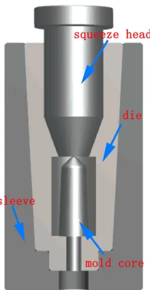
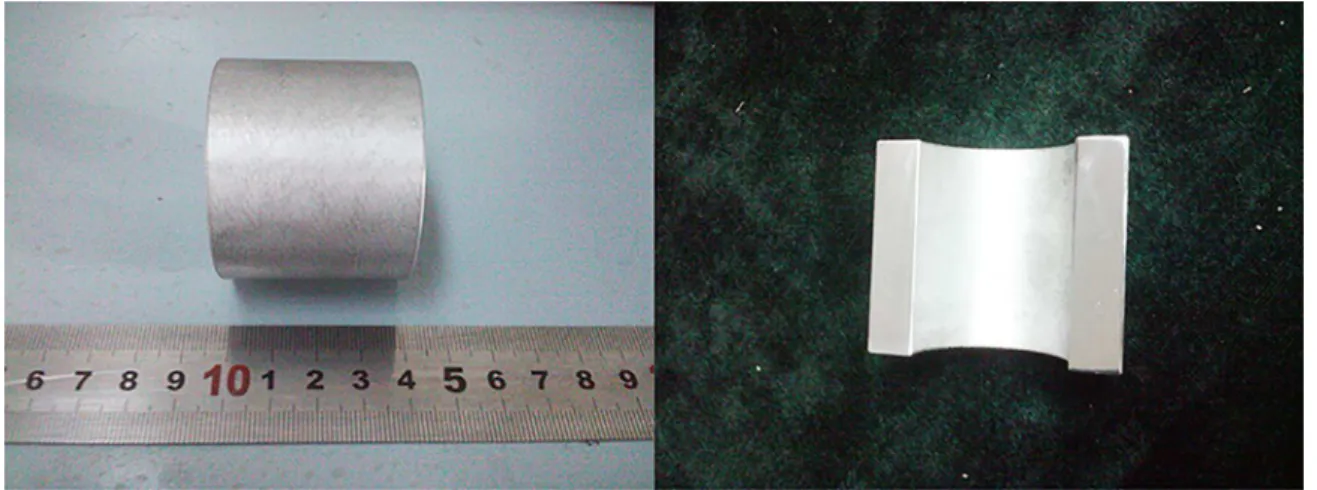
Semi-solid squeeze casting was carried out in a 50 ton-hydraulic machine. The semi-solid slurry was transferred into a mould preheated to 200 ºC (Fig. 1). The slurry was pressed at 50 MPa for approximately 10 to 15 s. The squeezed Al alloy pipe was split along the axial direction into two halves (Fig. 2).
The samples were prepared along the longitudinal direction of the squeezed pipe. After pre-grinding, fine-grinding, and polishing, the specimens were etched with 0.5% hydrofluoric acid. Optical microscopy (Leica, Co.) was used to observe the metallographic structure. Measurements of the equivalent diameter (ED) of the hard phases were carried out using image-analysis techniques. ED was determined from the following equation:
(1)
Where: A is the area of the hard phase particle, we can obtain it by the Image-pro plus software suite.
A scanning electron microscope (SEM) (VEGA-3SBH, Tescan Co. & S-3400N, Hitachi Co.) was used to observe the microstructures, fracture morphology, and abrasion morphology. The phase analysis and the structure of Fe-rich phases of the alloys were analysed by using a Focused Ion Beam (FIB) for sampling (Quanta 3D FEG SEM/FIB Dual Beam, FEI Co.) and Transmission Electron Microscopy (TEM) (Tecnai G2-F30-S-TWIN, FEI Co.), respectively.
Five points were chosen along the radial direction to test the macro-hardness of the pipe wall with its gradient structure. The micro-hardness of the Si- and Fe-rich phases was measured using a Vickers hardness tester at 25 gf. Fig.
Figure 1. Punch and die arrangement.
D=2 rA
Figure 2. Cross-section of the squeezed pipe.
Figure 3. Mechanical testing of pipes (a) sampling positions of the pipe for abrasion test and testing of the tensile strength; (b)
pin-on-disk wear resistance testing; (c) tensile test specimens.
3. Analysis of the Microstructures of
Semi-solid Squeeze Cast Alloy Pipe Walls
3.1. Microstructural characteristics of semi-solid
squeeze cast alloy pipe walls
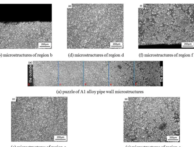
The microstructures of semi-solid rheological squeeze casting A1 alloy pipe wall are shown in Fig.4. Fig. 4(a)
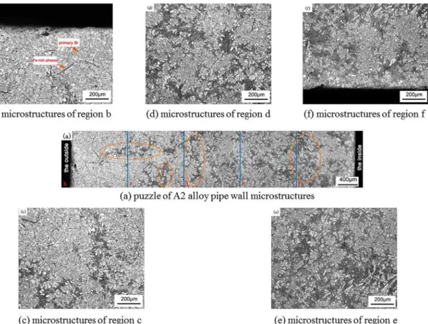
distribution of grey particles in the A2 alloy wall presented a gradual increase, different sized “segregation islands” (Si-poor regions) were present in the radial section of the pipe wall (red circles), in which the distribution of primary Si was discontinuous. It was noteworthy that the number of “liquid segregation islands” was greater than that in A1 alloy, and the acicular Fe-rich phases (Al4FeSi2 phases) were distributed
around the boundaries of the “liquid segregation island”. As shown in Fig. 6, no acicular Fe-rich phases were seen in the radial microstructures of the A3 alloy (with its added elemental Fe and Mn) pipe wall, replaced by the blocky Al15(Fe, Mn)3Si2 phases. The micro-hardness of
Figure 4. Rheo-squeeze casting A1 alloy pipe wall with gradient structure (a) puzzle of A1 alloy pipe wall microstructures; (b - f)
microstructures of regions b - f.
Figure 5. Rheo-squeeze casting A2 alloy pipe wall with gradient structure (a) puzzle of A2 alloy pipe wall microstructures; (b - f)
microstructures of regions b - f.
Under the influence of the blocky Al15(Fe, Mn)3Si2
phases, the VF of the hard phases in each region of the A3 alloy wall is higher than that in the corresponding regions of the A1 and A2 alloy walls, which makes the volumes of the higher hardness region of the A3 alloy wall greater than that of the corresponding regions in the A1 and A2 alloy walls. In summary, the macro-hardness of each region in the alloy wall is significantly associated with the VFs of hard phases of each region.
3.2. Preliminary analysis of the mechanism
underpinning the formation of the gradient
structure alloy pipe wall produced through
semi-solid squeeze casting
In comparison with Figs. 4 ~ 7, it was found that the EDs and VFs of the hard particles (primary Si and the blocky α-Al15(Fe, Mn)3Si2 phase) gradually increased from
the outer surface to the inner surface of the pipe wall. In the first of filling, the driving force of the liquid phase flow during semi-solid rheo-squeeze casting process is the pressure difference in the various parts of the sample 15.
The liquid phase tends to flow towards the lower volume under pressure. At a certain squeeze speed, the slurries of the alloys flow along the surface of the mould core to the
bottom of the cavity. Then, in the radial direction, the fine primary Si particles can be carried to the wall of the mould with the liquid phase. Finally, the slurries condensed under pressure and a pipe with a radial gradient of particle forms and sizes was produced.
There are a large number of acicular Fe-rich phases in the A2 alloy, which hinder the flow of the liquid phase and cause flow along the edge of acicular Fe-rich phase particles. This was why a liquid phase flow belt formed and, as can be seen from Fig. 6(c) and (d), the acicular Fe-rich phase was distributed along both sides of the flow belt, and the VF of the liquid difference of both sides of some acicular Fe-rich phase crystal was obvious. This caused liquid segregation of the A2 alloy pipe to be the most significant among the three types of alloy pipe walls tested.
3.3. Analysis of the crystal lattice parameters of
different types of Fe-rich phases
Based on previous studies14, the Al
4FeSi2 phases (acicular
Fe-rich phases) obtained under high cooling rates were identified as having a tetragonal structure, and the blocky or Chinese script-Al15(Fe, Mn)3Si2 phases (precipitated out in
Figure 6. Rheo-squeeze casting A3 alloy pipe wall with gradient structure (a) puzzle of A3 alloy pipe wall microstructures; (b - f)
microstructures of regions b - f.
Figure 7. Relationships between the macro-hardness and the hard
particles’ VFs of the pipes.
Al15(Fe, Mn)3Si2 phase were analysed. Fig. 8 shows the TEM
bright-field images and selected area diffraction patterns of
the Al4FeSi2 phase and the laminar Al15(Fe, Mn)3Si2 phase
(sampled from the blocky phase by focused ion beam). The analysis showed that the Al4FeSi2 phase was in the form of
a tetragonal structure with lattice constants a = 0.60641 nm
and c = 0.95258 nm, and the blocky Al15(Fe, Mn)3Si2 phase
was a body centred cubic structure with lattice constants a=
0.75198 nm and c = 0.77688 nm.
Figure 8. TEM images of Fe-rich phases (a) bright-field and SAPD
4. Effect of Fe-rich Phase Morphology on
Wear Resistance and Tensile Strength
ofthe Pipe Wall
It can be seen from Table 2 that the mass loss and wear rate of A2 alloy were the largest in the wear testing of three types of alloy pipe inner surface, while the A3 alloy was the smallest. With increasing wearing test time, the wear rate of the A2 alloy increased most among the three alloys. Therefore, as the data showed, the inner surface of the A3 alloy pipe had the best wear resistance, followed by that of the A1 alloy, with A2 alloy being the worst.
Fig. 9(a) shows the wear morphology of A1 alloy after 1800 s under a load of 20 N at a speed of 500 rpm. There were shallow furrows and a lower plastic shearing lip in the wear surface. There were fewer spalling pits and less tearing at the top of the plastic shear lip. There was a small amount of fine grinding particles on the wear surface under these test conditions.
Fig. 9(b) shows the wear morphology of the A1 alloy after 7200 s under a load of 20 N load at a speed of 500rpm. The uneven furrows can be seen in Fig. 9(b), and some of the furrows are deeper. There was evidence of a plastic deformation shearing lip on both sides of the furrow (indicated by the arrow in the figure), the top of which had deep spalling pits and tearing. There were a large number of the bigger grinding particles seen on the wear surface. The particles were formed by the spalling of primary Si during repeated rolling; because of the excessive load in the wear process, deformation of the worn surface occurred, and the harder particles acted repeatedly and fractured during the prolonged friction wear process, causing the primary Si particles at the top of the shear lip to fall off and form a spalling pit. The adhesion and rolling action of the two contact friction surfaces in the process of friction wear meant that the larger shear stress tore the plastic shear lip, which was the key fatigue wear mechanism. The falling Si particles gathered in the groove, and played the role of micro-cutting to deepen the groove, which was the key abrasive wear mechanism. The wear of A1 alloy was not a single wear mechanism but a combined action of adhesive wear and abrasive wear under long-term, high-speed friction.
Fig. 9(c) and (d) show the wear morphologies of the inner surface of the A2 alloy pipes. Fig. 9(c) shows the surface morphology of wear samples under a load of 20 N after 1800 s. It can be seen that there are many sheet like fragments falling off the matrix in the wear surface. Some of the fragments were distributed in the top part of the plastic deformation area, and some of the fragments were partly distributed around the bottom of the furrows. There were larger wear particles at the bottom of the furrows. The wear surface morphology of the inner wall of the A2 alloy pipe after wear testing for 7200 s is shown in Fig. 9(d). The surface was badly worn and there were only a few furrows
on the surface. The surface of the worn sample spalled and many particles covered the surface abscission zone. Many of these particles had been crushed to form an oxide particle layer. The wear resistance of the inner surface of the A2 alloy pipe was the lowest because the worn surface suffered the spallation of sheet-like fragments during the wear process.
Fig. 9(e) and (f) show the wear morphologies of the inner surface of the A3 alloy pipes. Fig. 9(e) shows the surface morphology of wear samples under a load of 20 N after 1800 s: the plastic shear lip in the figure is obvious, and the top part of the shear lip evinced tearing of the material. There were varying shades and width of furrows in the wear surface. There were a few wear particles at the bottom of the furrows, and there were abrasive particles seen at the edges of the furrows, which were formed by rolling of the detached particles, therefore, under these conditions, the wear mechanism of the inner surface of the A3 alloy pipe was mainly adhesive wear, accompanied by a certain abrasive wear mechanism. Fig. 9(f) shows the surface morphology of wear samples under a load of 20 N load after 1800 s: there were unevenly distributed furrows and wear particles of different sizes on the wear surface. Therefore, under these conditions, the wear mechanism was mainly abrasive wear, accompanied by slight adhesive wear.
Through tensile test, that the tensile strength of the inner sides of the three types of alloy pipes were 96.55 MPa, 76.73 MPa, and 95.96 MPa, respectively (the volume fraction of the hard phase was higher and the average diameter was larger on the inside). The A2 alloy pipe had the lowest tensile strength as it contained a large number of acicular Fe-rich phases: the A1 and A3 alloy tensile strengths were similar. The tensile strengths of the outer part of the three alloys were increased compared with the inner part, which were 125.58 MPa, 83.80 MPa, and 112.54 MPa, respectively. It should be noted that the VF of the hard phase was lower and the ED was smaller in the outer part. It can be concluded that the tensile strength of the inner and outer sides differed due to the VF of hard phases, that is, the higher the VF and the larger the ED, the lower the tensile strength, and vice versa. The appearance of the bulk α-Al15(Fe, Mn)3Si2 phase in the
micro-structure had little effect on the tensile strength of the alloy, but the acicular Fe-rich phase impaired the tensile properties of the alloy.
Figure 9. Worn morphologies of the inner faces of pipes’ walls: (a, c, e) the worn surfaces of A1, A2, A3 alloy pipe walls for 1800s; (b,
d, f) the worn surfaces of A1, A2, A3 alloy pipe walls for 7200s.
Table 2. Wear test data of the inner face of the A1, A2 and A3 alloy pipes
Load and
wear speed Wear time/s
A1 alloy A2 alloy A3 alloy
loss weight/
mg wear rate loss weight/mg wear rate loss weight/mg wear rate 500r/min,
20N
1800s 13 0.46% 30 1% 6 0.48%
Figure 10. Fracture morphologies of the inner part of the A1, A2, and A3 alloy pipes.
and a smooth tearing section can be seen at the position indicated by the arrow. Fig. 10(c) shows the tensile fracture of the A3 alloy. There were many cleavage platforms and a large number of dimples on the surface, therefore, the A3 alloy fracture was also deemed to have been a brittle fracture.
By means of Fig.10, it can be deduced that there were significant stresses acting in the specimens during the tensile testing of the A1, A2, and A3 alloy pipes and that these were mainly parallel to the direction of applied tensile load. Many micro-cracks were seen to be distributed on the surface of the primary Si particles and blocky α-Al15(Fe, Mn) 3Si2 phase,
and the stress concentration was the most obvious at the tip of the crack. The main cracks formed at these micro-cracks and propagated under the action of the applied tensile force. The crack would have continued to propagate along the acicular Fe-rich phase boundary and the edge of the lamellar structure when the main cracks propagated to the acicular Fe-rich phase or the lamellar eutectic Si structure. A fracture was formed perpendicular to the direction of application of tensile force after crack confluence.
5. Conclusions
High-Si Al alloy pipe with gradient structure can be produced through semi-solid squeeze casting. During the process of semi-solid slurry filling, the slurry flow along the surface of the mould core to the bottom of the cavity.
Then, in the radial direction, the fine primary Si particles are carried to the wall of the mould with the liquid phase. However, acicular Fe-rich phases (Al4FeSi2 phases) hinder
the flow of the liquid phase and cause liquid segregation in the microstructures of the pipe wall. Thereby, this effects the gradient varying of the macro-hardness at the pipe wall, and the Al4FeSi2 phases even worsen the wear resistant
and tensile properties of alloy. The blocky Fe-rich phases
(Al15(Fe, Mn)3Si2 phases) are in favour of the wear resistant
property, and have little impact on tensile properties of alloy wall. Meanwhile, the TEM analysis showed that the
Al4FeSi2 phase was in the form of a tetragonal structure
with lattice constants a = 0.60641 nm and c = 0.95258 nm,
and the blocky Al15(Fe, Mn)3Si2 phase was a body centred
cubic structure with lattice constants a= 0.75198 nm and c = 0.77688 nm.
6. Acknowledgement
on the Microstructure and Properties of the Hypereutectic Al-Si Alloy in Automotive Piston. Advanced Materials Research. 2013;744:339-344.
5. Cui C, Schulz A, Schimanski K, Zoch HW. Spray forming of hypereutectic Al-Si alloys. Journal of Materials Processing Technology. 2009;209(11):5220-5228.
6. Zak O, Tonn B, Baesgen A, Kallien L. New Wear Resistant Hypereutectic AlSi14Cu4FeCrMn Alloys for High Pressure Die Casting. International Journal of Metalcasting. 2015;9(4):49-57.
7. Lin C, Wu S, Lü S, An P, Wan L. Effects of ultrasonic vibration and manganese on microstructure and mechanical properties of hypereutectic Al-Si alloys with 2% Fe. Intermetallics. 2013;32:176-183.
Advanced Materials Research. 2008;47-50:865-868.
12. Yang Z, Zhang HF, Wang AM, Ding BZ, Hu ZQ. Formation of the High Chromium White Iron Parts with Gradient Structure Via Semi-Solid Metal Extrusion. Acta Metallurgica Sinica. 2003;39(2):164-167.
13. Nafisi S, Ghomashchi R. Semi-Solid Processing of Aluminum Alloys. Cham: Springer; 2016. p. 296-297.
14. Li L, Zhou RF, Lu DH, Jiang YH, Zhou R. Effect of cooling slope and manganese on the microstructure of hypereutectic Al-Si alloy with 2% Fe. Materials Research. 2014;17(2):511-517. 15. Vieira EA, Ferrante M. Prediction of rheological behaviour