On the Effect of Aluminum on the Microstructure and Mechanical Properties of CrN
Coatings deposited by HiPIMS
Monica Costa Rodrigues Guimarãesa, Bruno César Noronha Marques de Castilhoa* , Carlos
Cunhaa, Wagner Rafael Correrb, Paulo Mordentec, Fernando Alvarezd, Haroldo Cavalcanti Pintoa
Received: September 22, 2017; Revised: January 05, 2018; Accepted: February 22, 2018
Hard coatings are a suitable solution for increasing the lifetime of tools and components employed
in different industrial applications. Coatings of transition metal nitrides have great use for tribological applications due to due to their unique mechanical properties. Although widely employed, current deposition methods such as cathodic arc evaporation produce coatings with many defects, which in turn reduce the resistance to wear, especially under severe conditions. High Power Impulse Magnetron Sputtering is a novel physical vapor deposition technique that produces homogeneous coatings. In this study, CrN and CrAlN monolayer coatings were deposited on AISI 304 stainless steel substrates using HiPIMS. X-Ray Diffraction, Scanning Electron Microscopy, Atomic Force Microscopy were
used to evaluate the microstructure, phase composition, morphology and chemical composition of the
coating. Results showed that HiPIMS is a promising technique to deposit CrN and CrAlN homogeneous coatings with high hardness and good adhesion to the substrate.
Keywords: HiPIMS, hard coatings, CrN, CrAlN, characterization.
*e-mail: [email protected].
1. Introduction
Physical Vapor Deposition is a widely used method
for coating deposition in industrial scale1. It consists in the creation of a vapor phase from a target by either evaporation
or sputtering. The vapor phase then condensates on a substrate to form the coating or film. The use of magnetrons on the target and the application of high power impulses allows a higher degree of ionization combined with better densification and reduction or full elimination of defects on the coating in a technique called High Power Impulse Magnetron Sputtering (HiPIMS)2-4.
One of the main strengths of HiPIMS is the use of impulses instead of the continuous power supply, which allows for a higher peak power without melting or causing
damages to the target5. Another attractive advantage is the possibility to use the ion etching as a previous step before
coating deposition. The ion etching promotes a final cleaning of the coating by using high voltage to ionize either argon or metal ions towards the substrate. The collision of these ionized atoms cleans the surface of the impurities that could not be previously removed. This allows a better adhesion of the coating, which cannot be achieved by other Magnetron
Sputtering techniques2,5,6.
Amongst the numerous materials that can be sputtered, transition metal nitrides are the most used for tribological
applications. Titanium and titanium aluminum nitrides have
been used for high wear resistance applications but failed in high temperature applications with oxidation occurring at 600°C7. Therefore, researches have been conducted to
explore solutions with higher thermal and chemical stability. Chromium nitride shows promising results for these severe
conditions and the addition of aluminum, up to 68%at, acts as
a substitutional component in CrN lattice structure and showed improved results with different deposition techniques8-10.
The aim of the present work is to characterize monolayer coatings of CrN and CrAlN deposited on stainless steel by HiPIMS and to compare their structural and mechanical properties. X-Ray Diffraction, Scanning Electron Microscopy (SEM), Atomic Force Microscopy (AFM), Nanoindentation and Scratch tests were applied to characterize the coating.
2. Experimental Details
2.1. Materials
HiPIMS deposited CrN and CrAlN coatings on AISI 304 austenitic stainless steel substrates. The 30 mm diameter substrates were ground and polished to a mirror finish (15, 9, 3 and 1 µm diamond paste followed by 0.05 µm silica) and they were ultrasonically cleansed in acetone. The ion etching and depositions were performed in a high vacuum chamber (Plasma-HIPIMS-250) system equipped with 200 mm X aEscola de Engenharia de São Carlos, Universidade de São Paulo, São Carlos, SP, Brasil
bInstituto de Física de São Carlos, Universidade de São Paulo, São Carlos, SP, Brasil cMAHLE Metal Leve, Jundiaí, SP, Brasil
100 mm pure chromium (99.5%) and chromium aluminum (99.5%) targets with 50-50at% composition. Substrates were
placed at the substrate holder at a distance of 65mm from
the target. A base layer of Cr was used for the CrN coating and a CrAl for the CrAlN coating to provide better adhesion.
2.2. Coating process
The chamber was heated up to 400°C at a pressure of 1.0Torr for the ion etching process. Base layer and coating deposition parameters are described in Tab. (1). The working pressure was 4mtorr throughout the deposition process. The flow rate of argon and nitrogen was 40 and 50 sccm, respectively. The HiPIMS frequency was set to 400 Hz.
2.3. Characterization
The film crystalline structure was investigated by X-Ray Diffraction (XRD) using a MRD-XL Diffractometer (PANalytical, the Netherlands), with a Bragg-Brentano configuration (θ-2θ) and parallel beam geometry. The X-Ray parallel beam of 3x3mm2 was produced by a
Co-Kα radiation (1.78897Å, 40kV and 40mA) with a 2θ range from 34° to 110°, step size 0.05° and at 10s per step. XRD analysis was used for evaluation of preferred orientation growth. The calculations to determine texture coefficient utilized the equations proposed by Birkholz11 by means of
the equations (1) and (2).
(1)
(2)
In those equations, µ is the linear absorption coefficient (µCu = 1215cm-1), t is the film thickness, and I is the intensity
of hkl plane either on the powder pattern (index ICDD) or the measured one (index m).
A Field-Emission Scanning Electron Microscope (FEG-SEM) Inspect F-50 (FEI, The Netherlands) was used to characterize the morphology at the top and the cross-section of the coatings.
The coating composition was measured by X-Ray Energy Dispersive spectrometer (Apollo X SDD, EDAX, USA) using a standard sample of CrN to calibrate the measurement. Surface roughness was calculated from AFM images obtained in a Nanosurf FlexAFM (Nanosurf, Switzerland). A PB 1000 nanoindenter (Nanovea, USA) equipped with a Berkovich diamond indenter was used to measure hardness. For each
sample, twenty points separated by a distance of 15µm were measured with a load of 150mN at the top and 50mN at the cross-section and the average hardness and standard deviation were calculated. To evaluate the adhesion of the coatings to the substrate, scratch tests were carried out using the same NanoveaPB 1000. The tests were performed with conical diamond indenter (200µm radius) using progressive load from 0N to 100N at a loading rate of 100N/min and the scratch length of 4mm.
3. Results and Discussion
3.1. EDX analysis
Table (2) presents the chemical composition of the coatings measured by EDX analysis. The values are close to the expected stoichiometry. For CrN coating a 50-50at% composition was expected and for the CrAlN coating the composition was expected to be 50at% of nitrogen and 25at% of chromium and aluminum. The N2 and Ar flow rate are the main responsible for the deposited content of nitrogen and the metals, respectively12-14. Therefore, the measured
values indicate a correct adjustment between the flow rate
of nitrogen and the sputtering rate of the metals adjusted by
the flow rate of argon.
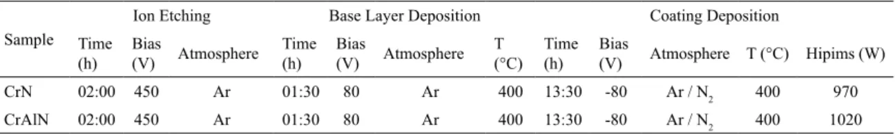
Table 1. Process parameters for sample deposition.
Sample
Ion Etching Base Layer Deposition Coating Deposition
Time
(h) Bias (V) Atmosphere Time (h) Bias (V) Atmosphere T (°C) Time (h) Bias (V) Atmosphere T (°C) Hipims (W)
CrN 02:00 450 Ar 01:30 80 Ar 400 13:30 -80 Ar / N2 400 970
CrAlN 02:00 450 Ar 01:30 80 Ar 400 13:30 -80 Ar / N2 400 1020
/ ( ) / ( ) T I I A l A I
(hkl)
hkl ICDD hkl m hkl hkl hkl m hkl hkl hkl ICDD 2 2 i i R R
= i i
i i
( ) exp
A sen t 1 2 hkl 2 i i n = -
-i -i
T
T YY
Table 2. Results of EDX analysis showing stoichiometric composition. Chemical composition [at%]
Cr Al N
CrN 49.36 - 50.64
CrAlN 26.83 26.38 46.79
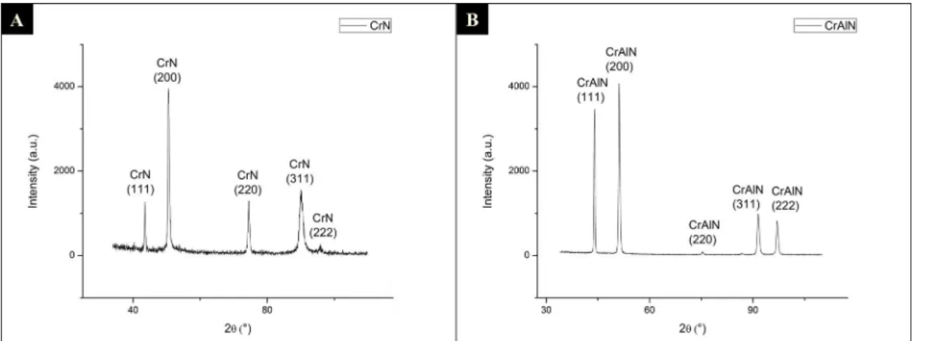
3.2. XRD analysis
Figure 1. XRD analysis of (A) CrN and (B) CrAlN coatings
Figure 2. Texture coefficient showing preferential orientation growth on (311) plane for CrN coating
element on the lattice structure reduces the lattice parameter
causing a shift in the 2θ values8. It is evident that the latter is more pronounced and therefore the shift to higher values
of 2θ is observed.
The texture coefficient was calculated based on the diffractograms in Figure 1. The results are shown in Figure 2. The change of preferred orientation growth can be observed by both Figures. Whilst CrN shows texture on the (311) plane, CrAlN texture coefficient is close to 1 to almost all planes, which means it is close to the powder diffraction pattern. Furthermore, for CrAlN, (222) plane has predominant growth.
3.3. Microstructure
Figure (3) shows SEM images of CrN (a and c) and CrAlN (b and d) from cross-section and top view. The microstructure of CrAlN coating on substrate surface from top view shows smaller grains than CrN. No growth defects (droplet) can be observed on the film surface and both shows a dense microstructure although they presented some inter-columnar voids. Cross-section images (Fig.3 (a), (b)) show columnar structure.
The coatings thickness were measured according to the Fig. 3 (a) and (b). CrN coating presented a thickness of 16.6±0.2µm while CrAlN had 18.8±0.2µm thickness. This means that, as the deposition time is the same for both samples, CrAlN showed higher deposition rate, which in principle contradicts the literature. The slightly higher applied power could be the reason for such discrepancy.
Surface morphology of the coatings was studied using AFM. In Fig. (4) (a) and (b) are shown the 3D AFM images of CrN and CrAlN respectively. The root mean square (RMS) roughness values are 0.239µm and 0.158µm whilst the average roughness (RA) shows 0.184µm and 0.120µm
for CrN and CrAlN respectively. The value for the CrAlN coating is smaller than for the CrN coating and it is related
to the fact that the CrAlN coating has smaller columnar grains when compared to the CrN.
3.4. Mechanical and tribological properties.
3.4.1. Nanohardness
Figure 3. SEM images of cross-section of (A) CrN and (B) CrAlN, and the surface morphology of (C) CrN and (D) CrAlN
Figure 4. AFM Images of the surface of (A) CrN and (B) CrAlN films. CrN shows higher mean roughness
growth of magnetron sputtered coatings. Better conditions of the energy and the flux of ion bombardment for CrN
coatings, such as an increase of the bias voltage, can ensure higher hardness and better mechanical properties because
of high coating density, without voids in the microstructure. The increase of the bias also promotes a change in preferred orientation from (100) to (220) showing high hardness and
high residual compressive stress15,16.
The difference of hardness between CrN and CrAlN can be attributed to the presence of aluminum on the latter. The
addition of aluminum up to 68% increases the hardness of
the coating by solid solution, due to the lattice deformation. After that, the aluminum forms an AlN hexagonal phase, which reduces the coating hardness 17,18. As the percentage
of aluminum was below this value, a higher hardness was found on the CrAlN coating.
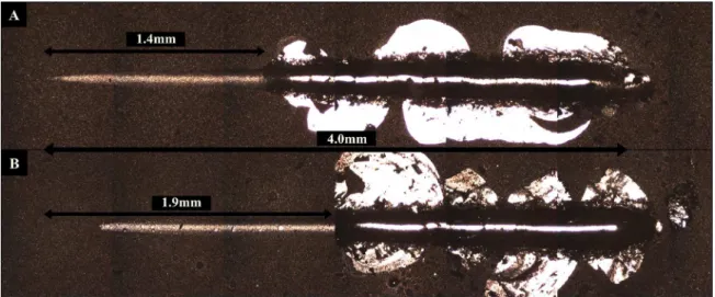
3.4.2. Scratch
Three scratch tests were performed 2mm apart for both CrN and CrAlN coatings. Critical load (Lc) measurements
for adhesion strength were 34.5N and 46N respectively. Both coatings failed by delamination as can be observed from Fig.(5), which indicates adhesion failure. The higher value achieved by CrAlN coating indicates better adhesion to the substrate than the CrN coating. The lack of cohesive
failure in both cases indicates the high homogeneity of the
coatings. The lower values of Lc obtained in this work, in
comparison with other similar studies, can be attributed to
the pores in the coating and the voids are not advantageous
for good adhesion. In addition, the bias may not have been sufficient to etch away the oxides of the substrate. Despite that, the coatings showed better results than those deposited
Figure 5. Scratch test on (A) CrN and (B) CrAlN coatings. CrAlN showing better adhesion than CrN coating
4. Conclusions
In this study, CrN and CrAlN monolayer coatings were produced using the HiPIMS technique. The CrAlN coating showed higher hardness, lower surface roughness and better adhesion to the substrate than the CrN coating. The XRD data showing peak shifts on the 2θ scale and the lack of AlN peaks in the CrAlN coating confirms the presence of aluminum as a substitutional element in the CrN lattice structure. CrAlN deposited by HiPIMS shows promising results towards its applications as a high wear resistance coating. Further studies will correlate the hardness and adhesion of the coating with the residual stresses and texture and the optimization of these properties as a function of various deposition parameters.
5. Acknowledgements
The Authors would like to thank MAHLE Metal Leve and BNDES (Decision Dir. 640/2012) for funding. MCRG and BCNMC acknowledge CAPES and CNPq for the scholarships. HP is a CNPq fellow.
6. References
1. Rodríguez RJ, García JA, Medrano A, Rico M, Sánchez R, Martínez R, et al. Tribological behaviour of hard coatings deposited by arc-evaporation PVD. Vacuum. 2002;67(3-4):559-566.
2. Helmersson U, Lattermann M, Bohlmark J, Ehiasarian AP, Gudmundsson JT. Ionized physical vapor deposition (IPVD): A review of technology and applications. Thin Solid Films.
2006;513(1-2):1-24.
3. Mishra B, Moore JJ, Lin JL, Sproul WD. Advances in Thin Film Technology through the Application of Modulated Pulse Power Sputtering. Materials Science Forum. 2010;638-642:208-213.
4. Ehiasarian AP, Münz WD, Hultman L, Helmersson U, Petrov I. High power pulsed magnetron sputtered CrNx films. Surface
and Coatings Technology. 2003;163-164:267-272.
5. Sarakinos K, Alami J, Konstantinidis S. High power pulsed magnetron sputtering: A review on scientific and engineering state of the art. Surface and Coatings Technology.
2010;204(11):1661-1684.
6. Ehiasarian AP, Wen JG, Petrov I. Interface microstructure engineering by high power impulse magnetron sputtering for the enhancement of adhesion. Journal of Applied Physics.
2007;101(5):054301.
7. Xu YX, Riedl H, Holec D, Chen L, Du Y, Mayrhofer PH. Thermal stability and oxidation resistance of sputtered Ti-Al-Cr-N hard coatings. Surface and Coatings Technology. 2017;324:48-56.
8. Kimura A, Kawate M, Hasegawa H, Suzuki T. Anisotropic lattice expansion and shrinkage of hexagonal TiAlN and CrAlN films.
Surface and Coatings Technology. 2003;169-170:367-370.
9. Ehisarian AP, Hovsepian PE, Hultman L, Helmersson U. Comparison of microstructure and mechanical properties of chromium nitride-based coatings deposited by high power
impulse magnetron sputtering and by the combined steered
cathodic arc/unbalanced magnetron technique. Thin Solid Films. 2004;457(2):270-277.
10. JakubéczyováD, HagarovaM, Hvizdoš P, CervováJ, FrenákM. Tribological Tests of Modern Coatings. International Journal of Electrochemical Science. 2015;10(9):7803-7810.
11. Birkholz M. Thin Film Analysis by X-Ray Scattering. Weinheim:
Wiley-VCH; 2006.
12. Pulugurtha SR, Bhat DG. A study of AC reactive magnetron
sputtering technique for the deposition of compositionally
graded coating in the Cr-Al-N system. Surface and Coatings Technology. 2006;201(7):4411-4418.
13. Zhang ZG, Rapaud O, Bonasso N, Mercs D, Dong C, Coddet C. Control of microstructure and properties of dc magnetron sputtering deposited chromium nitride films. Vacuum.
2008;82(5):501-509.
14. Shah HN, Jayaganthan R, Kaur D, Chandra R. Influence of
sputtering parameters and nitrogen on the microstructure of
direct-current reactive magnetron sputtering. Thin Solid Films.
2010;518(20):5762-5768.
15. Grasser S, Daniel R, Mitterer C. Microstructure modifications of CrN coatings by pulsed bias sputtering. Surface and Coatings Technology. 2012;206(22):4666-4671.
16. Kong Q, Ji L, Li H, Liu X, Wang Y, Chen J, et al. Influence of
substrate bias voltage on the microstructure and residual stress of
CrN films deposited by medium frequency magnetron sputtering.
Materials Science and Engineering: B. 2011;176(11):850-854.
17. Ding XZ, Zeng XT. Structural, mechanical and tribological properties of CrAlN coatings deposited by reactive unbalanced magnetron sputtering. Surface and Coatings Technology.
2005;200(5-6):1372-1376.
18. Cavaleiro A, de Hosson JT, eds. Nanostructured Coatings. New