Cable Robot for Non-Standard Architecture and
Construction: a Dynamic Positioning System
Eduardo Moreira
∗, Andry Maykol Pinto
†, Paulo Costa
†, A. Paulo Moreira
†,
Germano Veiga
∗, Jos´e Lima
§, Jos´e Pedro Sousa
‡, and Pedro Costa
††INESC TEC and Faculty of Engineering, University of Porto, Portugal
§INESC TEC and Polytechnic Institute of Braganc¸a, Portugal ‡Faculty of Architecture, University of Porto, Portugal
∗INESC TEC
Email: [email protected],{andry.pinto, paco, amoreira}@fe.up.pt, [email protected], [email protected], [email protected], [email protected]
Abstract—In the past few years, cable-driven robots have received some attention by the scientific community and the industry. They have special characteristics that made them very reliable to operate with the level of safeness that is required by different environments, such as, handling of hazardous materials in construction sites. This paper presents a cable-driven robot called SPIDERobot, that was developed for automated construc-tion of architectural projects. This robot has a rotating claw and it is controlled by a set of 4 cables that allow 4 degrees of freedom. In addition to the robot, this paper introduces a Dynamic Control System (DCS) that controls the positioning of the robot and assures that the length of cables is always within a safe value. Results show that traditional force-feasible approaches are more influenced by the pulling forces or the geometric arrangement of all cables and their positioning is significantly less accurate than the DCS. Therefore, the architecture of the SPIDERobot is designed to enable an easily scaling up of the solution to higher dimensions for operating in realistic environments.
I. INTRODUCTION
In the last few decades, the automation level of the manu-facturing industry has been remarkable because technological advances in robotics led to the introduction of robotic arms, au-tonomous guided-vehicles and sophisticated machinery, which made possible to automate entire production processes. Unfor-tunately, the civil engineering field suffers from a slower rate of automation [1], [2] due to several problems that characterize the construction sites: hard and hazardous environments. For robotic systems operate correctly in this type of environments, they must be designed and developed by taking into considera-tion some relevant features that are important for heavy duties: endurance, flexibility, maintenance and reliability.
In this context, cable driven robots appear to be an interest-ing solution because their construction is relatively simple and inexpensive (multiple cables attached to a mobile platform) and they are easy to transport, assembly and disassembly in different construction sites due to the lightweight of the cables. Moreover, they provide large workspaces, high pay-loads and reliable stiffness in lateral directions under external disturbances [3]. Although cable-driven robot being a strong possibility for construction of civil structures, there are some issues that must be considered before implementing of a real and fully-sized solution, namely: the workspace is reduced by the inability of cables to push (non-negative tension), cable
in-terferences and collision with nearby objects. These problems have challenged the researchers and some approaches can be found in recent literature [3]–[5]. Most of these approaches consider the controllable workspace of cable-driven robots using force-feasible. There are two categories for the kine-matics model defined with respect to the distribution of cable forces [6]: constrained and under-constrained. The fully-constrained completely determines the position and orientation of the robot as a function of the cables length. This means, when considering a mobile robot with n degrees of freedom (DOF) the model is fully-constrained if the number of cables exceeds the number of DOFs. For under-constrained robots, its position and orientation cannot be completely determined by the cable’s length (depends on the gravity force). The actuation of each cable controls the positioning and orientation of cable-driven robots however, solutions based on force-feasible restrict the workspace because they require a positive tension in all cables [7]. This represents a straight disadvantage and inconvenience for realistic solutions.
geometric arrangement of the all cables and the positioning is significantly more accurate (see the results section). In addition, the DCS does not use sensors to measure the tension of cables however, it requires a localization system which it could be, in a construction site, a GPS or vision-based system. In this research, a vision-based system was implemented for the SPIDERobot that gives information about the location of the moving platform and the pose (position and orientation) of parts that are available in the environment.
The paper is organized as follows: the related works about cable-driven robots are presented in section II and section III presents the system description, kinematic’s model and the positioning control system of the SPIDERobot. Results of section IV prove the ability of the robot for pick-and-place operations, since the proposed DCS is more accurate than conventional force-feasible approaches because a high level of precision was achieved during the manipulation of parts (even with only four cables). Finally, major conclusions of this work are discussed in section V.
II. RELATEDWORKS
Cable-driven robots, also known as array or cable-suspended robots, control an end-effector using multiple actu-ated cables [8]. Cables are controlled usually by a positioning system [9] that actuates in motors for rolling and unrolling cables. These robots are capable of performing many manip-ulation tasks and they have several conveniences over typical robotic manipulators [5]: a smaller number of moving parts, a lower level of visual intrusion [4], a larger working area and a higher payload ratio relative to the robot’s weight. On the other hand, cable interferences, inaccuracies at the end-effector due to cable stretch, and the limited force in the downward directions are some the disadvantages of cable-driven robot [8].
Currently, there is a small number of cable-driven robotic systems available on the market of sports and entertain-ment [9], namely, the SkyCam1 and the Cablecam2. However,
a larger number of researching works can be found in the literature [3], [7], [10], and regarding to this type of robots. Al-though these works resort to a considerable diversity of robots with different geometries, number of cables and application fields, the large majority of them use tensor-feasible controlling systems for positioning the mobile robot in the workspace. In detail, the robot presented in [10] was designed for contour crafting. This robot has 12 cables that made possible to control the position of the end-effector. From this amount of cables, 4 upper-cables are used to support the weight of the mobile platform and the remaining 8 bottom-cables (grouped in pairs) are used by the positioning system to control the robot. The major disadvantages of this type of robots is that bottom-cables cause a severe reduction of the workspace and there is a higher probability of collisions between the cables and nearby objects. Authors try to solve this problem by introducing horizontal crossbars in the frame where the robot is installed. These crossbars are actuated vertically which elevates the position of the bottom-cables and increases the workspace. Although a very stable and clever solution, this approach requires a lot of hardware due to the amount of cables and the elevation
1SkyCam, www.skycam.tv 2CableCam, www.cablecam.com
of the bottom-cables. A cable-driven robot with the moving platform having a triangle shape is presented in [3]. This platform is supported by 6 upper-cables, where a couple of cables is installed in each vertex. The research studied the dy-namic aspects of the reachable domain in terms of achievable positions by presenting a Lyapunov-based controller with the positive tension constraint. The authors restrict their analysis to translational motions which misses the advantage in terms of DOF that can be achieved by using 6 cables.
A cable-driven robot with self-calibration for aquatic sens-ing applications is proposed in [6]. This 2 DOF robot was designed for planar translation and it is formed by four cables which means actuation redundancy. The research proposed a controlling system for real-time computation of tensor dis-tributions because the cable redundancy often results in an infinite set of tension distributions. A suspended robot with 4 upper-cables can be found in [7]. The position of the mobile platform is achieved by controlling the length of those cables in two operation modes: planar (3 DOFs) and spatial (4 DOFs) and, therefore, this type of configuration can operate like an under-constrained or a fully-constrained system, however, the paper focused on path-planning for parallel robots and results show that the method is able to detect and to avoid collisions among the mobile platform and the objects in the workspace. Thus, the proposed robot can be used for realistic pick-and-place operations. The same authors suggested a real application for their robot in [11], in moving patients between beds in a hospital.
III. THESPIDEROBOT
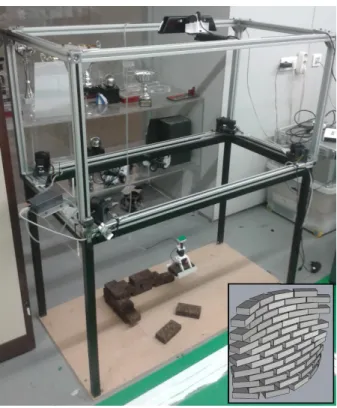
This paper presents a low-cost robotic application with 4 DOFs and called SPIDERobot. It was developed for assem-bling architectural projects, see Fig. 1, and so, the main goal is for picking-and-place operations, in order to build walls such as illustrated in the lower right corner of Fig. 1. The robot is formed by 4 upper-cables and a rotating claw, installed in the mobile platform and connected using an universal joint. The most conventional approach for controlling the Cartesian position (XYZ) of the platform is to measure the tension/length of each cable. As already been discussed, there are several disadvantages of this approach. Which are the reason why this article proposes a dynamic control system (DCS) for acting directly in cable lengths, and without the feedback of the tension value.
Figure 1 shows the SPIDERobot and the frame where it is installed (1.20 ×0.6×1.35 meters). The platform can be approximated as a single point in space since all cables passes though the platform and converge to a single point, close to the universal joint. As can be noticed, the XYZ position of the moving platform (40 ×30 × 15 mm, without the claw) can be obtained by controlling each cable length, by rolling or unrolling the cables using servo motors with encoders. A global vision system was introduced, which is based on a RGB-D camera, for computing the current position of the mobile platform, as well as, to detect parts that might be available in the environment. This information is essential for the DCS to positionate the robot in specified locations and to avoid the undesirable release of cables, see section III-C.
envi-Fig. 1. Physical layout of the SPIDERobot. In the right-bottom it is depicted a possible architectural project that is desired for this robotic platform.
ronment and according to a executing order, which is usually a set of sequential dropping points that are configured offline. The universal joint means that the claw is always parallel to the floor, independently of the platform position and, enabling the full and autonomous construction of structures.
A. System Architecture
The system architecture for the SPIDERobot, see Fig. 2, is composed by 3 distributed modules: vision, obstacle avoidance and dynamic controlling system.
First, a list of positions is available for the control appli-cation. This list represents a sequential set of dropping points, represented in the world reference, that avoids the need for a scheduling system that, otherwise, must be implemented in order to decompose the architectural project into executing orders (picking, transporting and dropping parts).
The controller of the SPIDERobot receives information from the obstacle avoidance module which is responsible for setting a collision-free path to the robot. Obstacle avoidance is an important feature for cable-driven robots because the movement of the platform can jeopardize the safeness of the working area (collisions of the platform or cables). This obstacle avoidance module receives information from a vision application, that analyses the environment, detects the robot, identifies parts and sends information about possible picking positions (one for each dropping order). The architecture depicted in Fig 2 permits good responses from the robot to dynamic environments since the vision module is constantly analyzing parts that might be available at random poses and the obstacle avoidance plans safe trajectories. The biggest advantage of this architecture is that, the robotic solution
Ask for possible Pick Positions Return possible
Pick Positions CSV File with
DropPositions
Current Position of the robot
Desired Position
Obstacle Avoidance (Path Planing)
Vision Application
Dynamic Controlling System
Cable Control State Control
Fig. 2. Global System Architecture of the proposed cable-driven robot.
can be scaled up to more realistic dimensions and without significant changes.
Obviously, the DCS controller has no knowledge about the environment and it is responsible only for the correct positioning of the robot, as well as, the safe rolling/unrolling of cables. The vision module gives information about the localization of the mobile platform that can be used to correct the position of the robot. The correction leads to a better behavior for the control module (see results). The vision and obstacle avoidance modules are out of the scope of this article and, therefore, the moving platform will execute linear L-shape paths (for picking and dropping parts).
B. Kinematic’s Model
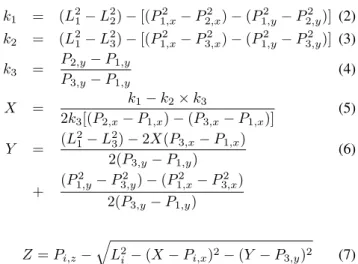
According to the layout described in Fig. 1, it is possible to estimate the length of each cable using the Euclidean distance between the top corner of the frame and the current position of the platform.
Li= (X−Pi,x)
2
+ (Y −Pi,y)
2
+ (Z−Pi,z)
2
(1)
Equation 1 represents the length for each cable, where
i ∈ {1,4} is the cable number, Pi = (Pi,x, Pi,y, Pi,z)is the respective corner position, and (X, Y, Z) is the position of the mobile platform in the Cartesian space.
k1 = (L 2
1−L
2
2)−[(P
2
1,x−P
2
2,x)−(P
2
1,y−P
2
2,y)] (2)
k2 = (L 2
1−L
2
3)−[(P
2
1,x−P
2
3,x)−(P
2
1,y−P
2
3,y)] (3)
k3 =
P2,y−P1,y P3,y−P1,y
(4)
X = k1−k2×k3
2k3[(P2,x−P1,x)−(P3,x−P1,x)]
(5)
Y = (L
2
1−L
2
3)−2X(P3,x−P1,x)
2(P3,y−P1,y)
(6)
+ (P
2
1,y−P
2
3,y)−(P
2
1,x−P
2
3,x)
2(P3,y−P1,y)
Z=Pi,z−
q
L2
i −(X−Pi,x)2−(Y −P3,y)2 (7)
It is also important to notice that, knowing the current position of the robot (X,Y,Z) requires only the length of 3 cables. This cable redundancy can be observed in Equations 5 to 7. As expected, it is possible to use any combination of cables to determine the current position (3 DOF) of the SPIDERobot.
C. Positioning system
A controller plays an important role in characterizing the reachable domain [3] of cable-driven robots, since motion of the system is based on cable lengths. This section presents the Dynamic Controlling System (DCS) that controls the move-ment of the robot using the feedback of its current location (given by a vision module). The current position is used to verify if the movement was completed and to calculate the length of all cables, which is the control variable of this system. The previous section III-B has demonstrated a redundancy in the number of cables, which means an infinite set of lengths for each position of the SPIDERobot (with all the cables not being fully extended). This causes controlling issues regarding changes in the spooling radius of the release mechanism, that compromise the correct functioning of the robot. The DCS was especially conceived for this purpose since it controls the position of the robot using the available information and assures the retraction of cables that are less tensioned. In this way, the method is formed by two control loops, see Fig. 3. An inner loop corrects the positioning based on a visual location of the robot and the outer loop is responsible for compensating possible drifts in the cable length.
Figure 3 depicts clearly the DCS operation. Correcting the releasing problem (inner-loop) requires to estimate the cable lengths based on the vision location in order to determinate the estimation error that was obtained by the encoder of each motor (odometry-based). The outer-loop measures the error between the desired and the real position of the moving platform. The resulting error is combined with the contribution from the inner-loop that signals the motors (after a PID controller).
This topology maintains all cables close to fully extended and assures the correct positioning of the robot. In addition, it produces a stable behavior, high repeatability and a control-lable approximation of the claw to the part.
Desired Position Cable Lengths
Vision Cable Lengths
PID Controller errL
+
-Estimated Cable Lengths from Encoders
ΔerrL
Convert to Cable Lengths Vision Position Motors Convert to Cable Lengths Desired Position Control Signal State Control Environment + -+
-Fig. 3. Schematic of the Dynamic Controlling System (DCS) based on visual information and estimated cable lengths.
IV. RESULTS
Extensive experiments were conducted as part of this research to evaluate the effectiveness of the DCS as a real-istic alternative to tension-feasible controlling systems. Each experiment is formed by a real scenario where the proposed robot picks 4 stacked parts3 and drops those parts in
pre-defined positions. These dropping positions reflect different quadrants in the world coordinate system. Considering this testing scenario, several trials were performed and the position (vision and kinematic) of the robot was studied. Note that, in the beginning of each trial both positions are equal and all cables are fully extended. In this way, it is possible to compare the error evolution during the entire trajectory and if the robot is able to conduct the desired orders with the required accuracy.
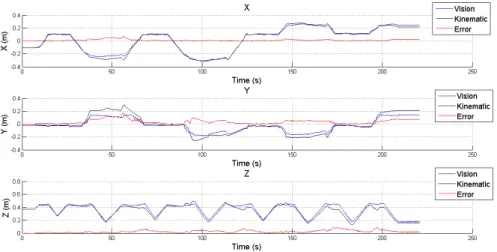
Figure 4 shows the evolution of the position and the associated error in a single trial. From the analysis of these graphs is possible to verify an increasing of the error over time for the kinematics estimation (represented in red). As expected, estimating the position of the robot using the kinematic model (tension/length of cables and encoders) causes errors. This is a known and well documented problem in mobile robotics [12]– [14]. These errors were higher for the Y and Z coordinates and they are related to the finite resolution of encoders and the cables have a small elasticity that is not considered in the system model.
It is possible to analyze in Fig. 5 the position of the robot, according to the vision and during a similar trial4. The robot is using the vision module (considered as ground truth), otherwise, it cannot pick-and-place all parts if the estimate of the kinematic model is considered since the accumulated error leads to an unsuccessful picking of the fourth part. Small variations of the robot position, especially in the upper corner of the trajectory are a result of minor corrections due to the inner-loop of the controller that actuates in order to maintain all cables extended and within safe values. To analyze better the implication of the accumulated error in each axis, the Euclidean error was separated in the XY plane and Z coordinate. This separation reinforces the importance of the robot to approach each part with the correct XY and
3Parts were placed all stacked with unknown position and unknown
orien-tations.
Fig. 4. Temporal evolution of the position of the robot (X, Y and Z coordinates) given by the vision system (blue) and the kinematics (black). The kinematic’s error is represented in red.
Fig. 5. Position of the SPIDERobot given by the vision module and during the pick-and-place of 4 parts. Coordinates are described in the world reference.
considering that Z is a variable that can be actuated separately (due to the L-shaped path). The temporal evolution of these errors are represented in Fig. 6. During the execution of this trial, there were instants where the kinematics error was high (up to 0.19m for XY and 0.08m for Z position). The high error in the kinematics positioning compromises the correct operation of the SPIDERobot, since parts have small size (0.06×0.12×0.03m).
The overall XYZ error of this trial can be observed in Fig. 7. An important result is the accumulation of error increases over time which means that the average error is also increasing. This figure clearly demonstrates that controlling the position using the kinematic model is not the best choice, since the error tends to accumulate over time. A statistical analysis for this trial is presented in Table I. Without the introduction of vision its clear that the correct picking of the parts would be very difficult since the error is in average greater than0.03m in XY and 0.05m in XYZ.
Fig. 6. Temporal evolution of the Euclidean error in XY and Z.
Fig. 7. Temporal evolution of the Euclidean error in XYZ.
TABLE I. STATISTICS OF THEEUCLIDEAN ERROR
Axis MEAN (m) STD (m) MAX (m) X 0.013 0.013 0.070 Y 0.036 0.034 0.172 Z 0.027 0.020 0.091 XY 0.039 0.035 0.185 XYZ 0.052 0.033 0.188
DCS, with the vision module guarantees an accurate and stable positioning of the robot. Results prove that the accumulated errors of the kinematics would be too large for small sized applications. This would lead to a necessity of introducing high quality sensors for each cable, for measuring tension. Taking all results into consideration, it is quite clear that at some point in the trajectory, the claw could completely miss a pick-and-place operation if a high quality external sensoring system is not available.
V. CONCLUSION
The research presented in this paper introduces the SPI-DERobot which is a 4 DOF (one of them is given by the claw rotation) robot. Unlike the majority of the related works, the robot presented by this paper is not controlled based on tensor-feasible, which means that, the positioning controller must con-sider the actuator redundancy (4 cables). Therefore, a dynamic controlling system (DCS) is also proposed which is formed by a double control-loop: first, the position of the robot is controlled using information obtained by an external localiza-tion system (vision-based) and, secondly, the rolling/unrolling process in each actuator is automated/compensated by consid-ering the cables error that are estimated. Results show that the DCS made possible an accurate positioning of the robot (for pick-and-place scenarios) which, otherwise, could not be achieved using a low-cost tensor-feasible approach (that lead to a position error of0.052m). In this way, this robotic prototype can be scaled up to realistic environments without significant changes in the software architecture. Results demonstrate that, the DCS proved to be a realistic approach for a industrial applications since it makes possible the execution of accurate tasks by the mobile platform: transportation, picking-and-place and others.
In future works, the influence of an obstacle avoidance routine will be studied in a dynamic environment, with the purpose of granting the optimization and safeness during the trajectories that are made by the robot.
ACKNOWLEDGMENT
This work is partly funded by the project PTDC/ATP-AQI/5124/2012 - Robotic Technologies for Non-Standard De-sign and Construction in Architecture. This work is also financed by the ERDF European Regional Development Fund through the COMPETE Programme (operational programme for competitiveness) and by National Funds through the FCT Portuguese Foundation for Science and Technology within project ”FCOMP - 01-0124-FEDER-022701”
The authors also thank the contribution of Ant´onio Moreira and Mariana Oliveira.
REFERENCES
[1] M. Hastak, “Advanced automation or conventional construction pro-cess,”Automation in Construction, vol. 7, no. 4, pp. 299 – 314, 1998. [2] P. Vh, T. Heikkil, P. Kilpelinen, M. Jrviluoma, and E. Gambao, “Ex-tending automation of building construction survey on potential sensor technologies and robotic applications,” Automation in Construction, vol. 36, no. 0, pp. 168 – 178, 2013.
[3] S.-R. Oh and S. Agrawal, “Generation of feasible set points and control of a cable robot,”Robotics, IEEE Transactions on, vol. 22, no. 3, pp. 551–558, June 2006.
[4] M. Gouttefarde, D. Daney, and J.-P. Merlet, “Interval-analysis-based determination of the wrench-feasible workspace of parallel cable-driven robots,”Robotics, IEEE Transactions on, vol. 27, no. 1, pp. 1–13, Feb 2011.
[5] J. German, K. W. Jablokow, and D. J. Cannon, “The cable array robot: Theory and experiment,” in Robotics and Automation, 2001. Proceedings 2001 ICRA. IEEE International Conference on Robotics & Automation Seoul, Korea, vol. 3. IEEE, 2001, pp. 2804–2810. [6] P. Borgstrom, B. Jordan, B. Borgstrom, M. Stealey, G. Sukhatme,
M. Batalin, and W. Kaiser, “Nims-pl: A cable-driven robot with self-calibration capabilities,”Robotics, IEEE Transactions on, vol. 25, no. 5, pp. 1005–1015, Oct 2009.
[7] S. Lahouar, E. Ottaviano, S. Zeghoul, L. Romdhane, and M. Ceccarelli, “Collision free path-planning for cable-driven parallel robots,”Robotics and Autonomous Systems, vol. 57, no. 11, pp. 1083 – 1093, 2009. [8] K. Usher, G. Winstanley, and R. Carnie, “Air vehicle simulator: an
application for a cable array robot,” inRobotics and Automation, 2005. ICRA 2005. Proceedings of the 2005 IEEE International Conference on. IEEE, 2005, pp. 2241–2246.
[9] P. H. Borgstrom, N. P. Borgstrom, M. J. Stealey, B. Jordan, G. Sukhatme, M. A. Batalin, and W. J. Kaiser, “Generation of energy efficient trajectories for nims3d, a three-dimensional cabled robot,” in Robotics and Automation, 2008. ICRA 2008. IEEE International Conference on. IEEE, 2008, pp. 2222–2227.
[10] P. Bosscher, R. L. W. II, L. S. Bryson, and D. Castro-Lacouture, “Cable-suspended robotic contour crafting system,” Automation in Construc-tion, vol. 17, no. 1, pp. 45 – 55, 2007.
[11] E. Ottaviano, M. Ceccarelli, and M. De Ciantis, “A 4-4 cable-based parallel manipulator for an application in hospital environment,” in
Control Automation, 2007. MED ’07. Mediterranean Conference on, June 2007, pp. 1–6.
[12] A. M. Pinto, A. P. Moreira, and P. G. Costa, “A localization method based on map-matching and particle swarm optimization,” Journal of Intelligent and Robotic Systems, pp. 1–14, 2013.
[13] A. M. Pinto, L. F. Rocha, A. P. Moreira, and P. G. Costa, “Shop floor scheduling in a mobile robotic environment,” inProgress in Artificial Intelligence, ser. Lecture Notes in Computer Science, L. Antunes and H. Pinto, Eds. Springer Berlin Heidelberg, 2011, vol. 7026, pp. 377– 391.
[14] A. M. G. Pinto, A. P. Moreira, and P. G. Costa, “Indoor localization system based on artificial landmarks and monocular vision,” TELKOM-NIKA, vol. 10, no. 1, pp. 609 – 620, 2012.