ABSTRACT: Bird’s formation light is one of the best types of cooperation in nature. The bird’s light was the motivation of humans for lying. After one century of light development, bird’s formation light was the motivation of humans for aircraft’s formation light. The closeness of aircrafts in formation light and the effect of disturbances such as vortex make the formation light control a challenging issue for control designers. This paper introduces a novel integration between guidance commands and system controller inputs. In recent papers the control system inputs were derived from approximate equations, and this approximation caused maneuver limitation. To tackle this problem, a new method is introduced, which employs proportional-integral-derivative (PID) controller in the integration block. This integrated guidance and control system employs the pure pursuit guidance to determine the unmanned aerial vehicle’s acceleration command. A two-loop dynamic inversion technique is used for designing attitude and velocity controller, while the acceleration feedback control is used between the guidance system and attitude controller, which leads to increase in maneuverability of unmanned aerial vehicle’s formation light. The simulation results show that the proposed method can control the UAV’s formation with suficient accuracy in severe maneuvers.
KEYWORDS: Formation light, Non-linear dynamics, Pure pursuit, Integrated guidance and control.
A Novel Integrated Guidance and Control
System Design in Formation Flight
Mohammad Sadeghi1, Alireza Abaspour1, Seyed Hosein Sadati1
INTRODUCTION
Unmanned aerial vehicle (UAV) deployments tend to be increasing and their uses seem to be expanding in many aspects. Surveillance, reconnaissance, sampling, and crop-dusting are just some of UAV applications (Watts et al. 2012).
In order to guide an UAV in the desired trajectory, the acceleration commands and the angular velocities of the UAV should be calculated by the guidance system. The task of guidance law is to calculate the translational acceleration and angular velocities in order to send them to autonomous light control system (Lin 1991).
UAV guidance is performed on vertical and lateral-direction. Vertical guidance has to set the vertical distance in the desired point. This system calculates the necessary angle of attack based on vertical distance error and commands them to the longitudinal control system of UAV. he lateral guidance system has to set the UAV in the desired lateral path as well. his system calculates the bank angle commands — in bank to turn (BTT) systems — or side slip angle — in skid to turn (STT) systems — and send them to lateral control system of UAV. Based on the chosen guidance law, the lateral and longitudinal guidance commands can be obtained in two decouple system or in a unique system (Lin 1991; Siouris 2004; CDISS 2003). his paper investigates the leader-follower UAV’s formation light with 3-D pure pursuit guidance method and dynamic inversion light controller.
In order to enhance the maneuverability of the UAV, dynamic inversion (DI) method is used for designing attitude and velocity controller. DI is a non-linear control technique based on feedback linearization method which eliminates the gain scheduling need by the inversion and cancellation of the
1.Malek Ashtar University of Technology – Aerospace Research Center – Department of Aerospace Engineering – Tehran/Tehran – Iran.
Author for correspondence:Alireza Abaspour | Malek Ashtar University of Technology – Aerospace Research Center – Department of Aerospace Engineering 1774-15875 – Tehran/Tehran – Iran | Email: [email protected]
inherent dynamics, through replacement with a set of user-selected desired dynamics (Reiner et al. 1995). Most of the light controllers designed in this methodology was applied in both longitudinal and lateral/directional axes. his method has been implemented in high-performance aircraft, such as the F-117A (Colgren and Enns 1997) and the F-18HARV (Enns et al. 1994), and other modiied versions of the F-18 (Adams et al. 1994) and the F-16 (Adams and Banda 1993). In this paper a DI technique with two-time scale separation (Sadati
et al. 2007; Abaspour et al. 2013) is applied for the attitude and velocity control of UAV.
Guidance law is the process of generating position commands, and the output of this process is used by light controller. In contrast with missile guidance, collision avoidance is another important factor in formation of light guidance. Consequently, the guidance law should hold the head of follower UAV toward the leader UAV, and the velocity control system has to keep the relative desired distance from the target UAV.
he two common guidance laws are proportional navigation (PN) and pure pursuit (PP) guidance law. In this paper PP guidance method is chosen for formation design. The PN method can be also considered as well, but when the PN is used in formation light, it tends to guide away from the target when the closing velocity is negative (the leader velocity is greater than the follower UAVs) (Yamasaki et al. 2009). On the other side, the PP guidance always guides the UAVs independent of the follower and leader velocities. For these reasons, in this paper the pure pursuit guidance law is applied for the formation light guidance system.
In Giulietti et al. (2001) a formation flight control scheme was proposed based on the concept of formation geometry center, which is also known as the formation virtual leader. More complex control laws based on Linear Quadratic Regulator (LQR) and DI approaches have also been proposed in Schumacher and Kumar (2000) and Singh et al. 2000.An adaptive approach to vision based on UAV formation control using estimated line of sight (LOS) range was proposed by Sattigeri and Calies (Sattigeri et al. 2004).Tahk et al. (2005) suggested LOS guidance law for formation flight. The standard synthesized linear quadratic (LQ)-based structure for formation position error control in close formation flight of autonomous aircraft was described in Giulietti et al. (2000). The formation-keeping control problem for the three-dimensional autonomous formation flight was addressed in Yang et al. (2004) and Min and Tahk (2005).
In order to achieve the desired level of performance and maneuverability, one needs to provide both the required piloting ability (i.e. “relexive skills”, typically achieved through a low level feedback control system) and a high-level knowledge of the set of vehicle’s achievable behaviors (Stengel 1993).
Stengel (1993) proposes a method for controlling maneuvered formation of autonomous non-holonomic vehicles with the purpose of obtaining a desired target region. his approach was based on tracking of pairs of virtual leaders whose control inputs are obtained in a single optimization process based on model predictive control (MPC) technique.
However, most of the previous results are restricted to two-dimensional formation problem, and full non-linear dynamics of the UAV model is not perfectly considered. Moreover, in previous designs, there was not any guarantee for maintaining formation in lateral acceleration maneuvers.In this paper, instead of routine formulation which was used in previous papers, a new feedback controller is introduced for calculating desired attitude commands from the acceleration commands. Unlike the previous formulation which was used for integrating guidance and control loop, this feedback controller helps to have continual supervision of system integration and, subsequently, a better control performance. As a result, this strategy can help to improve the accuracy of guidance system and formation control. For evaluating the proposed design, two UAV’s formation light, which were modeled by non-linear six degrees-of-freedom (DOF) equations, were used in the simulations. he simulation results show that the proposed method is signiicantly efective on maneuverability and formation accuracy.
he paper is organized as follows: in “Non-linear UAV Model” section the non-linear mathematical model of aircrat is extracted, whereas DI method is explained in “Dynamic Inversion” section, and the guidance method is described in “Guidance System Design” section. hen in “Numerical Simulations” section we proceed with the numerical simulation, while the conclusions are provided in the inal section.
NON-LINEAR UAV MODEL
Figure 1. The aircraft coordinate system.
lat Earth with respect to the body-ixed axis system are depicted in Fig. 1 and are modeled by the following diferential equations (Min and Tahk 2005).
where:
p, q, and r are components of airplane’s angular velocity regarding x, y, z body axes [rad/s]; Ix, Iy, and Izare moments of inertia [kg/m2] and I = I
xIz – Ixz
2; l, m,and n are aerodynamic
rolling, pitching, and yawing moment; M is mass [kg]; g is the acceleration due to gravity; V is the velocity; Fx, Fy, and Fz are guidance forcesabout the body-ixed frame [N]; α is the angle of attack [rad] or [deg]; β is the side slip angle [rad] or [deg];
θ and ϕ are Euler angles [rad] or [deg]; T means thrust [N];
L is lit [N]; ϕ is the rolling angle; θ is the angular velocity regarding to y axis; D is the drag [N].
The drag force, aerodynamic side force (Fy), lift force, and aerodynamic rolling, pitching, and yawing moment, which are used in Eqs. 1–8, can be obtained from the following equations:
V
z r p
q v
w y
δa δa
δr δe
x β α
u
(1)
(8)
.
(2)
(9)
(10)
(11)
(12)
(13)
(14) (3)
(4)
(6)
(7) (5)
where:
CD0 is the zero lift drag coefficient; CD is the drag coefficient;
b is the wing span [m]; c is the wing mean aerodynamic chord [m]; Cy is the aerodynamic force coefficient; CL is the lift coefficient; Cl, Cm and Cn are aerodynamic moment coefficients.
u, v and w: components of airplane velocity along x, y, and z body axes [m/s].
Ø = p+(qsinØ + rcosØ)tanθ
θ = qcosØ – rsinØ
.
Table 1.WVU YF-22 research aircraft speciication and aerodynamic coeficient in cruise light (Perhinschi et al. 2004).
In this paper a WVU YF-22 research airplane is chosen as a test-bed for running the designed aircrat formation light, whose speciication is available on Table 1.
DYNAMIC INVERSION
In this section, we present a feedback linearization technique known as dynamic inversion. DI is a non-linear control design technique based on feedback linearization method and uses a feedback signal to cancel inherent dynamics and simultaneously obtain a desired dynamic response (Reiner et al. 1995).
To elaborate the working principle of the non-linear DI (NDI), consider a system of order n with the same number m of
inputs u and outputs yand aine in the control inputs. Moreover, the outputs coincide typically to the control variables and are assumed to be physically similar (as an example, attitude angles). his type of system can be mathematically represented by:
where:
ωc is the design parameter chosen by the designer to obtain desire performance; subscript cdenotes the commands; subscript d denotes the desired value.
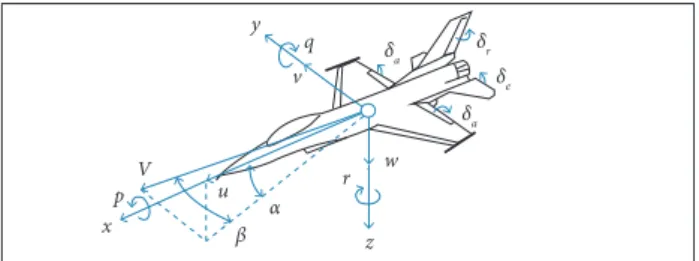
he required control can then be computed by inverting (15): where:
f and h are vector ields in Rn and Rm, respectively; G(x) is
a n × m control efectiveness matrix.
his system can be given to any desired dynamics by suitable choice of the control u (Enns et al. 1994). For example, the irst order dynamics given by Eq. 16 might be chosen.
Substituting Eq. 17 into Eq. 15, one clearly yields the desired dynamics of Eq. 16. The method can be extended to higher order systems and G(x)is invertible. In flight vehicle control problems, G(x) may be invertible if there
Geometric and inertial
c= 0.76 m b = 1.96 m S = 1.37 m2
Ix = 1.61 kg/m2 I
y = 7.51 kg/m
2 I
z = 7.18 kg/m
2 I
xz = –0.24 kg/m
2
M = 20.64 kg FTmax = 54.62 N
Longitudinal aerodynamic derivatives
CD0 = 0.0085 CDa = 0.5079 CDq= 0.0000 CDde= –0.0339
CL0 = –0.0492 CLa = 3.258 CLq = –0.0006 CLde= 0.1898
Cm0= 0.0226 Cma = –0.4739 Cmq= –3.449 Cmde= –0.3644
Lateral-directional aerodynamic derivatives
CY0 = 0.0156 CYb= 0.2725 CYp = 1.2151 CYr = –1.1618
CYda = 0.1836 CYdr = –0.4592
Cl0 = –0.0011 Clb = –0.0380 Clp = –0.2134 Clr = 0.1147
Clda = –0.0559 Cldr =0.0141
Cn0 = –0.0006 Cnb =0.0361 Cnp = –0.1513 Cnr = –0.1958
Cnda = –0.0358 Cndr = –0.0555
(15)
(16)
Figure 2. Overall view of designed dynamic inversion controller.
while the desired angular rates are deined by the following equation:
Inner
loop Aircraft dynamics
pc, qc, rc
δa δe
δr p
q r β
α ϕ
βc, αc, ϕc Outer
loop
– –
+ +
are sufficient control effectors; however, there will often be conditions where G(x)is nearly singular. This would result in excessively large commands and saturation of control effectors. The near singularity of G(x) is due to the fact that the control moment effectors produce very small forces and thus provide very little direct control of attitude angles. Thus, it is difficult to use dynamic inversion directly for flight vehicle with more or less standard control effectors.
In this paper the problem associated with the invertability of G(x) was overcome by separating the dynamics into slow and fast subsystems in two loops. he fast subsystem corresponds to the body axis angular rates, and the slow subsystem corresponds to the attitude angles. An exact inner loop inversion (fastest) was carried out by using the three control efectors: aileron, elevator, and rudder.
We named these two loops: inner loop, and outer loop controller. he overall diagram of control structure is shown in Fig. 2.
INNER LOOP CONTROLLER
he attitude rates are the fastest states in aircrat model, and in this design they are controlled by the inner loop controller. In two-timescale assumption light control system, the inner-loop controller is designed to control the fastest states by using the control input u, where the desired values of the fast states are given by the outerloop. Now for using dynamic inversion based on Eqs. 1–3, the fast diferential equation can be separated as:
where:
ωp, ωq, and ωr are inner-loop gain chosen by the designer to obtain desire performance; the subscript c denotes the commands.
OUTER LOOP CONTROLLER
In the outer loop, the controller is designed to control the slow states, and the output of outer loop is used as inner loop commands. he slow states are the attitude angles described in Eqs. 4-6. It is assumed that the fast states track their commanded values instantaneously and the control surface delection has no efect on the outer loop dynamics.
(18)
(19)
(20)
(21)
(22)
(23)
while G(x) and [fp fq fr]Tcan be derived from Eqs. 1–3.
Considering Eq. 17, the controller of inner loop yields:
Computing the relation between pc, qc, and rcand main control surfaces is diicult, so the small term Gs2(xs1) is neglected. Considering Eq. 21, the controller of outer loop yields:
while the desired angular variables’ derivatives deined by the following equation are:
where:
ωβ, ωϕ, and ωα are outer loop control gains, which are chosen by the designer to obtain desired performance; βc, αc, and ϕc
By using Eq. 22, the output of outer loop is derived as the following equation:
Table 2. Velocity controller look up table.
VELOCITY CONTROLLER
In this paper the guidance method, which is used for the trajectory tracking, is pure pursuit. Due to pure pursuit nature, this guidance system heads to a target point only, and does not care for the velocity control along the velocity vector. For this reason, a velocity control system is necessary to keep a desired distance from the given trajectory. he velocity controller is also designed based on the dynamic inversion approach, and the aircrat dynamics is considered as well.
According to the aircraft closeness in formation flight, velocity control has an important role for collision avoidance. he designed velocity controller, which is used in this paper, has two control loops. One of them is velocity and the other one is relative distance. his loop separation is based on time scale separation assumption. his conception is clearly shown in Fig. 3 with block diagram.
As it can be seen in Fig. 3, Rd and Vdare desired distance and velocity, respectively. he look up table block, which is drawn on Table 2, calculates Vd according to error from the reference (eR).
he DI velocity controller is designed based on Eq. 8. By solving this equation based on thrust force (FT) and replacing
Ua instead of V, and desired thrust force (FTd) instead of FT, the thrust command can be calculated. By dividing FTd with maximum thrust (FTmax), δT(thrust control input) can be obtained by following equation:
where:
Uais the control input and can be obtained as follows:
eR (m) Vd (m/s)
< –300 Vmax
–5 Vvirtual leader
0 Vmin
Figure 3. Velocity controller’s structure. Look
up table
Inverse velocity dynamics
posVirtual Leader
posfollower
Vfollower
V
&
pos
R
norm
Vd eV
eR
Rd
Aircrafts dynamics
+
+ +
– –
–
δT
(25)
(26)
pos: position.
δT = FTd/FTmax = {m.(Ua)–m.g.(–sinθ.cosα.cosβ+ cosθ.sinφ.sinα.cosβ)+D.cosβ}/{(cosα.cosβ)* FTmax}
Ua= KV.ev
where:
Kvis a control gain, and in this paper it is equaled to 1;
ev is the relative velocity error.
GUIDANCE SYSTEM DESIGN
he guidance system’s task in formation light is to direct the UAV in a path, which minimizes the leader and follower aircrat’s distance. In this system the needed acceleration for approaching to the leader aircrat is calculated, and its output is used as the control system input of the UAV (Lin 1991). he guidance system guides the UAV in two directions: vertical and horizontal. he vertical guidance calculates the vertical acceleration commands and the angle of attack, while the horizontal guidance is used to locate the aircrat in desired lateral path. his system does this task by comparing the current position in horizontal plane with the desired one; therefore, the system provides the needed acceleration to keep the aircrat with desired path. In other words, in bank to turn (BTT) systems, the horizontal guidance calculates the bank angle command. his command will be used in lateral position control (Siouris 2004; CDISS 2003).
Pure pursuit guidance law and proportional navigation guidance law are the most conventional methods which are used for guiding goals (Naeem et al. 2003). In this paper pure pursuit law is chosen for its simplicity and its accuracy in formation light (Enomoto et al. 2010).
PURE PURSUIT
Pure pursuit is one of the most conventional methods in guidance laws. In this law the follower has to keep its line of
Vf
dxref dy
ref
dzref
R
V
Virtual leader
Leader aircraft
sight in line of target movement. In other words, the direction of the velocity vector has to be in line with the target site (Naeem et al. 2003).
Just like missile system, we can use the pure pursuit guidance law in formation light. If we denote the line of sight vector between the follower aircrat and virtual leader (the desired point that follower track it) with R, and the follower aircrat speed vector with Vf to coincide the follower speed vector with line of sight, the following equation should be established:
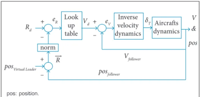
TRANSFORMATION OF GUIDANCE ACCELERATIONS INTO INNER LOOP CONTROLLER COMMANDS
The acceleration commands are achieved by guidance law, and the direction and magnitude of the force vector can be generated by the UAV’s slow dynamic states. In this paper, slow dynamic states are the angle of attack, side slip angle, and bank angle.
he system, which is used in this paper, is BTT. herefore, the desired side slip angle is zero. As a result, in order to obtain and maintain the formation, the angle of attack and bank angle should be obtained by the guidance commands. According to the fact that guidance commands are in inertial coordination, for making an integrated guidance and control, they should rotate from inertial axis to body axis. For this reason, the rotational matrix is used as follows (Fossen 2011):
Figure 4 shows the relation between R and Vf vectors, where
dxref denotes the distance between leader and virtual leader in longitudinal axis; dyref denotes the distance in lateral axis; dzref
denotes the distance in vertical axis. he acceleration commands for moving the aircrat toward the virtual leader is obtained from the following equation (Shneydor 1998; Yamasaki et al. 2008):
Figure 4. Pure pursuit tracking (Shneydor 1998).
(27)
(28)
(30)
(31)
(32) (29)
Finally, by using Newton’s second law and considering the weight, the needed guiding force is obtained as follows:
where:
g is the Earth’s gravity vector; M is the airplane mass; N is the navigational coeicient. In this equation the navigational coeicient is usually chosen between 0.5 to 3, and choosing a larger coeicient increases the amplitude of maximum guidance acceleration commands, especially in initial time of the formation.
where:
TB
NED is the rotation matrix from the North-East-Down
(NED) axes to the body axes;c denotes cosine; s denotes sine; Ψ is an Euler angle.
he angle of attack (α) and the bank angle (ϕ) generate the longitudinal and lateral acceleration in airplane guidance system, respectively. herefore, to reduce the diference between the acceleration commands from body coordinate (NzBguidance/NyBguidance) and the actual acceleration of airplane in body coordination (NzBaircraft/NyBaircraft), the control inputs of airplane attitude (αc, ϕc) should be calculated via acceleration error (ENzB/ENyB). his operation can be done through the control law (F) which is described as:
where:
F is the controller, which can be classic, adaptive or DI. As it can be seen in Fig. 5, in this paper PID controller is used for this purpose. In Fig. 5, Nzc_body and Nyc_body are the vertical and horizontal body coordination systems, respectively. Also, Nz_Res_body and Ny_Res_body
are the vertical and horizontal acceleration responses, respectively.
→
→ →
→
Vf× R = 0
he last step in formation light control design is integrating the control and guidance systems. he overall view of the designed system can be seen in Fig. 6. As it can be seen in this igure, to control and guide the follower UAV, only the virtual leader position is needed, which is easily available. The virtual leader position is subtracted from follower position, and the vector of R is obtained. his vector and the velocity vector are sent to guidance block, in which the needed acceleration is calculated for approaching to the virtual leader. hen, this acceleration is converted to angle of attack and bank angle by guidance-control integration block. Finally, the produced attitude commands are sent to outer loop controller for obtaining the desired position. In addition, the velocity controller has to obtain the desired distance between follower and leader, at the same time.
NUMERICAL SIMULATIONS
In this paper a novel integrated guidance-control system is designed for UAV formation purposes. In this section numerical simulation was carried out for evaluation of the introduced design. Several simulations using the WVU YF-22 model have been conducted, as a follower UAV. Table 3 gives the initial condition and parameter settings of these simulations. he
following assumptions were made to simplify the problem and to demonstrate the total system performance:
he UAV model is available and aerodynamic uncertainties are negligible.
he target UAV’s direction, distance and relative velocity information are available.
In order to evaluate the proposed design, a scenario is deined for formation light, whose speciication is available on Table 3. A virtual leader is assumed, which has a small distance in relation to the actual leader. his assumption is based on the collision avoidance of leader and follower.
he navigation constant is chosen as 1 and the integrator controller gains are set according to Table 4.
As it can be seen in Fig. 7, the follower aircrat tracked the virtual aircrat accurately. Despite the fact that a signiicant diference among UAV’s initial conditions was considered and the maneuver was complicated, the follower successfully tracked the virtual leader. Moreover, the follower has not any collision with the leader.
For a better formation analysis, the (x-y) and (x-z) plots of the formation are depicted on Figs. 8 and 9, respectively.
Figures 8 and 9 show that the designed system can track the desired trajectory accurately. he vertical command, which is produced by guidance system, is depicted on Fig. 10, in which the tracking of this command is depicted as well.
Figure 10 shows that the vertical acceleration error is successfully compensated by the angle of attack. Also, the tracking of the lateral acceleration, which is produced by guidance loop, is shown in Fig. 11, in which it can be clearly seen that the lateral acceleration error is successfully compensated by bank angle.
he control delection is another important factor for the control designers. he domain of their changes should not be larger than the actuator domains. Also, due to mechanical consideration, it is better to not have an oscillatory change in control delections. Figure 12 shows the control delection of the follower aircrat in the desired trajectory. As it can be seen, the aircrat has a desirable control delection.
Acceleration commands
Transfer from NED
to Body axes
PID
Controller (1) αc
Nzc_body
Nz_Res_body
Ny_Res_body
Nyc_body
+
+ –
–
ϕc PID
Controller (2)
posVirtual Leader posFollower
R V
Guidance block
G&C integrating
Slow state response
Fast state response
Follower aircraft dynamics Outer loop Inner loop
δT δa δe
δr
Velocity controller
NDI_attitude controller
ϕc
αc βc = 0
Nc_NED NRes_ body
+
+ +
–
– –
Figure 5. Guidance and control integrator.
Figure 6. The integrated guidance and control system diagram.
Table 3. Formation scenario.
Virtual leader’s position Leader’s position
Xvl = 100 + 150t
Xl = 110 + 150t Longitudinal axis
Yvl = 100 + 40sin(0.1t) + 2t
Yl = 110 + 40sin(0.1t) + 2t
Lateral axis
Hvl = 1100 + 40cos(0.1t) + 2t
Hl = 1100 + 40cos(0.1t) + 2t
Vertical axis
Table 4. The integrator controller speciication.
Ny
[m
/s
2]
Time [s]
0 –3 –1 1 3
Ny_command
Ny_respond
2 0 4 0 6 0 8 0 1 0 0
Aileron
Elevator Rudder
0 –1.5
–2 –1 –0.5 0 0.5 1
20 40 60 80 100
A
il
er
o
n
, E
le
va
to
r,
R
u
d
d
e
r [d
eg]
Time [s]
Nz
[m/s
2]
Time [s]
0 2 6 10 14
Nz_command
Nz_respond
20 40 60 80 100
Virtual Leader Leader Follower
U
p
[m]
East [m]
0 1,000 1,100 1,200 1,300
4,000 8,000 12,000 16,000
Figure 9. The (x-z) view of leader, virtual leader and the follower.
Figure 10. The longitudinal acceleration produced by guidance loop (Nz-command) and the follower tracking of it (Nz-output).
Figure 11. The lateral acceleration produced by guidance loop (Ny-command) and the follower tracking of it (Ny-response).
Figure 12. Control delection of aileron, elevator and rudder. Longitudinal
Lateral Gain
0 –0.01
Derivative gain
0.003 –0.08
Proportional gain
0.01 0
Integrative gain
Figure 7. The three-dimensional view of leader, virtual leader and the follower.
1,400
1,200
1,000
300 200 100 0 0 1 2
N orth [m] East [m]
Virtual Leader Leader Follower
× 104
Up
[m]
Figure 8. The (x-y) view of leader, virtual leader and the follower. Virtual Leader Leader Follower
N
o
r
th [m]
East [m]
0 0 100 200 300
4,000 8,000 12,000 16,000
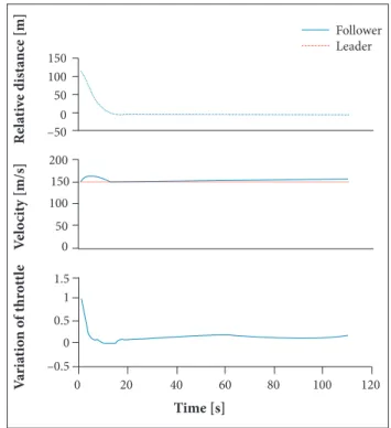
Figure 14. The designed control performance in velocity, relative-distance and throttle variation.
he velocity control is another important factor in formation design. hus, the ability of the proposed controller in tracking the desired speed and the desired distance with the leader is depicted on Fig. 14. he throttle which is the control input for velocity control is plotted in this igure, which demonstrates that the designed velocity controller has desirable performance.
CONCLUSION
In this paper a new integration method for integrating the control and guidance systems of an aircrat is introduced. Then, this method is used to establish aircraft formation
REFERENCES
Abaspour A, Sadeghi M, Sadati SH (2013) Using Fuzzy Logic In Dynamic Inversion Flight Controller With Considering Uncertainties. Proceedings of the 13th Iranian Conference on Fuzzy Systems; Ghazvin, Iran.
Adams RJ, Banda SV (1993) Robust light control design using dynamics inversion and structured singular value synthesis. IEEE T Contr Syst T 1(2):80-92. doi: 10.1109/87.238401
0 –2 0 0 5 –20 0 20 2 –5
20 40 60 80 100
p-Response
p-Command q-Response q-Command r-Response r-Command Time [s] Y aw r at e [d eg /s ] P itc h r ate [d eg /s ] R o ll r at e [d eg /s ] –20 0 5 10 –0.2 0 0.2 20 0 Response Command Response Command Response Command R o ll a n g le [d eg ] A n g le o f a tta ck [d eg ] S id e s li p [d eg ] Follower Leader
0 20 40 60 80 100 120
Time [s]
V ari at io n o f thr o ttl e V el o ci ty [m/s] R el at iv e dis ta nc e [m] 150 100 200 150 100 50 0 1.5 1 0.5 –0.5 0 50 –50 0
Figure 13. The DI control performance in tracking-commanded attitudes and rates.
light. he novelty of this method is using PID controller in integration block, instead of common formulation, which has been done in previous papers. his PID controller helped to have a better feedback from the control and guidance integration, and subsequently a better formation light. he dynamic speciication of WVU YF-22 research aircrat is used to demonstrate the ability of this method. Moreover, non-linear dynamic inversion is used to control the airplane attitude and its velocity. Finally, numerical simulation is done via MATLAB Simulink sotware. he simulation results show that the proposed method can successfully control the formation light in several maneuvers. From these results, it can be concluded that the introduced integration method can be used in order to integrate guidance and control precisely. Consequently, an accurate formation light is obtained by using the introduced method.
Adams RJ, Bufington JM, Banda SV (1994) Design of nonlinear control laws for high-angle-of-attack light. J Guidance Control Dynam 17(4):737-746. doi: 10.2514/3.21262
CDiSS (2003) Cruise missiles key technologies: an overview. Lancaster, UK: Center for Defence and International Security Studies.
Proceedings of the AIAA Modeling and Simulation Technologies Conference, AIAA; Reston, USA.
Enns D, Bugajski D, Hendrick R, Stein G (1994) Dynamic inversion: an evolving methodology for light control design. Int J Control 59(1):71-91. doi: 10.1080/00207179408923070
Enomoto K, Yamasaki T, Takano H, Bab Y (2010) A study on a velocity control system design using the dynamic inversion method. Proceedings of the AIAA Guidance, Navigation, and Control Conference; Toronto, Canada.
Giulietti F, Pollini L, Innocenti M (2000) Autonomous formation light. IEEE Contr Syst Mag 20(6):34-44.
Giulietti F, Pollini L, Innocenti M (2001) Formation light control: a behavioral approach. Proceedings of the 2001 AIAA GNC Conference; Montreal, Canada.
Lin CF (1991) Modern navigation: guidance and control processing. Englewood Cliffs, NJ: Prentice Hall.
Min BM, Tahk MJ (2005) Three-dimensional Guidance Law for Formation Flight of UAV. Proceedings of the International Conference on Control, Automation and Systems; Gyeonggi-Do, South Korea.
Naeem W, Sutton R, Ahmad SM, Burns RS (2003) A review of guidance laws applicable to unmanned underwater vehicles. J Nav 56(1):15-29. doi: 10.1017/S0373463302002138
Perhinschi MG, Napolitano MR, Campa G, Seanor B, Gururajan S (2004) Design of intelligent light control laws for the WVU YF-22 model aircraft. Proceedings of the AIAA 1st Intelligent Systems Technical Conference; Chicago, USA.
Reiner J, Balas GJ, Garrard WL (1995) Robust dynamic inversion for control of highly maneuverable aircraft. J Guidance Control Dynam 18(1):18-24. doi: 10.2514/3.56651
Sadati SH, Sabzeh Parvar M, Menhaj MB, Bahrami M (2007) Backstepping controller design using neural networks for a ighter aircraft. Eur J Control 13(5):516-526. doi: 10.3166/ejc.13.516-526
Sattigeri R, Calise AJ, Evers JH (2004) An adaptive vision-based
approach to decentralized formation control. Proceedings of the AIAA Guidance, Navigation, and Control Conference; Providence, USA.
Schumacher CJ, Kumar R (2000) Adaptive control of UAVs in close coupled formation light. Proceedings of the 2000 American Control Conference; Chicago, USA.
Shneydor N (1998) Missile guidance and pursuit: kinematics, dynamics and control. Woodgate, UK: Horwood Publishing.
Singh SN, Pachter M, Chandler P, Banda S, Rasmussen S, Schumacher CJ (2000) Input-output invertibility and sliding mode control for close formation lying of multiple UAVs. Proceedings of the 2000 AIAA GNC Conference; Denver, USA.
Siouris GM (2004) Missile guidance and control systems. New York: Springer.
Stengel RF (1993) Towards intelligent light control. IEEE Trans Syst Man Cybern 23(6):1699-1717. doi: 10.1109/21.257764
Tahk MJ, Park CS, Ryoo CK (2005) Line-of-sight guidance laws for formation light. J Guidance Control Dynam 28(4):708-716. doi: 10.2514/1.9605
Fossen TI (2011) Mathematical models for control of aircraft and satellites. Trondheim: Norwegian University of Science and Technology.
Watts AC, Ambrosia VG, Hinkley EA (2012) Unmanned aircraft systems in remote sensing and scientiic research: classiication and considerations of use. Remote Sens 4(6):1671-1692. doi: 10.3390/ rs4061671
Yamasaki T, Takano H, Baba Y (2008) Robust path-following for UAV using pure pursuit guidance. National Defense Academy, Japan.
Yamasaki T, Enomoto K, Takano H, Baba Y (2009) Advanced pure pursuit guidance via sliding mode approach for chase UAV. Proceedings of the AIAA Guidance, Navigation, and Control Conference; Chicago, USA.