Maria do Carmo Castro Henriques de Castro Fraga
Mestre em Engenharia Química e Bioquímica
P
ILOT SCALE MEMBRANE FILTRATION AND
DEVELOPMENT OF A PHOTOCATALYTIC
MEMBRANE REACTOR FOR TREATMENT OF
OLIVE MILL WASTEWATERS
Dissertação para obtenção do Grau de Doutor em Engenharia Química e Bioquímica – Especialidade em
Engenharia Química
Orientadora: Doutora Vanessa Ranhada Pinto Jorge Pereira Co-orientador: Professor Doutor João Paulo Serejo Goulão Crespo
Júri:
Presidente: Professora Doutora Maria Ascensão C.F. Miranda Reis Arguentes: Doutora Lidietta Giorno
Professora Doutora Rosa Maria de Oliveira Quinta-Ferreira
Vogais: Professora Doutora Maria Ascensão C.F. Miranda Reis
Doutora Vanessa Ranhada Pinto Jorge Pereira Engenheiro Paulo Garção Nunes
iii
Pilot scale membrane filtration and development of a photocatalytic membrane reactor for treatment of olive mill wastewaters
Copyright © Maria do Carmo Castro Henriques de Castro Fraga, Faculdade de Ciências e Tecnologia, Universidade NOVA de Lisboa. A Faculdade de Ciências e Tecnologia e a Universidade NOVA de Lisboa têm o direito, perpétuo e sem limites geográficos, de arquivar e publicar esta dissertação através de exemplares impressos reproduzidos em papel ou de forma digital, ou por qualquer outro meio conhecido ou que venha a ser inventado, e de a divulgar através de repositórios científicos e de admitir a sua cópia e distribuição com objetivos educacionais ou de investigação, não comerciais, desde que seja dado crédito ao autor e editor
iv
A
CKNOWLEDGEMENTSAo finalizar esta etapa tão importante na minha vida queria, antes de mais, agradecer aos meus orientadores, a Doutora Vanessa Pereira e o Professor Doutor João Paulo Crespo. Obrigada pela oportunidade que me deram de fazer este Doutoramento, num tema que sempre gostei, e por toda a amizade que senti ao longo deste tempo. À Vanessa agradeço a presença e generosidade constante, o tantas vezes ter atrasado o seu trabalho para apoiar o meu, e sempre com um sorriso. Por me ter ensinado que, no trabalho e na vida, são as pequenas coisas que fazem a diferença. Agradeço todo o apoio científico, rigor, exigência e perfeccionismo, que me fizeram querer sempre fazer mais e melhor. Ao Professor João agradeço tudo o que me ensinou, desde os tempos das aulas faculdade. Foram essas aulas que suscitaram o meu interesse pela área das membranas. Não tenho palavras para agradecer todas as oportunidades que me deu e conhecimentos que me transmitiu, científicos e humanos. Apesar de ser uma referência na área de membranas, com uma enorme experiência e imensos conhecimentos, ouve sempre a perspetiva dos alunos com a maior simplicidade. Sou uma privilegiada por ter sido orientada por duas pessoas incríveis. Muito muito obrigada aos meus dois orientadores.
Muito obrigada à Grupeta do Almoço: à Mafalda Lopes, Rita Valério, Joana, Mafalda Cadima, Maria João e Jorge, com os quais partilhei ótimos momentos. É tão bom quando no trabalho temos amigos que partilham das nossas alegrias e nos ajudam nas inquietações. Muito obrigada a todo o grupo da FCT.
Agradeço à Teresa ter-me recebido tão bem no laboratório e a alegria que contagia quem está à sua volta. Obrigada a todo o grupo pela partilha de um dia-a-dia que foi sempre muito bom. Agradeço em especial à Sandra, que me introduziu nas dinâmicas do laboratório, e à Beatriz Oliveira, por fazer do laboratório um lugar tão bom (e arrumado!) para se trabalhar. Agradeço à Rosita toda a amizade e a disponibilidade que teve sempre para me ajudar com o meu trabalho. À minha amiga Bea, agradeço por animar os meus dias sempre com uma boa conversa e muita alegria!
Um enorme e especial obrigada à minha irmã Sofia e á minha amiga Inês. Fizemos o caminho juntas desde as aulas na faculdade, com tantos e tão bons momentos partilhados. Cada uma à sua maneira contribuiu de forma muito especial no meu percurso do doutoramento. Obrigada por terem estado e continuarem sempre presentes.
Muito obrigada à minha família, meus queridos Pais, Irmãos, Tios, Avó e Didi, pelo interesse que sempre demonstraram no meu trabalho, pela motivação que me deram e por estarem sempre presentes na minha vida. À minha Mãezinha muito obrigada pelo apoio, principalmente pelas vezes que ficou com os meus filhos para que eu pudesse trabalhar no meu doutoramento. Ao Leonardo, meu marido, agradeço o apoio que me deu na decisão de fazer um Doutoramento e o muito interesse que sempre demonstrou naquilo que fiz. Por sempre me ter entusiasmado e
v elogiado o meu trabalho. Obrigada principalmente por esta fase final, em que fez tudo o que conseguiu para que eu pudesse dedicar-me à escrita. Aos meus filhos queridos, Benedita, Salvador e Vicente, agradeço serem a minha motivação para fazer as coisas bem feitas e lhes dar um bom exemplo. Agradeço os sorrisos, gargalhadas e choros que me acompanharam nesta fase final enquanto trabalhava em casa e me serviram de verdadeira inspiração! Muito obrigada por fazerem de mim uma pessoa melhor.
vi
A
BSTRACTThe work developed in this thesis focused on optimizing membrane processes and in the development of a novel hybrid photocatalytic membrane reactor to treat olive mil wastewaters. The traditional Mediterranean diet, known for being a rich and healthy diet, uses olive oil as its main source of fats. Therefore, in the Mediterranean region, there is an annual discharge of 30 million m3 of the wastewaters produced by this industry into the environment. Olive mill
wastewaters are a highly polluted effluent produced in olive oil industries, representing an environmental hazard if not treated properly. These effluents present low pH and a high concentration of solids, oil and organic compounds such as organic acids, lipids and alcohols. The presence of phenolic compounds hinders the biological treatment of these wastewaters. Membrane separation processes stand out as promising treatment approaches and their application has expanded during recent decades for the treatment of wastewaters, as a result of increasingly stringent regulations in wastewater discharge and continuing improvements in membrane technology. However, wide acceptance of membrane processes by industries is limited by membrane fouling. Fouling is caused by the accumulation of rejected oil, suspended solids and other components of the wastewaters on the membrane surface and intrapore structure. Fouling results in flux decline and low membrane lifetime due to the need to perform frequent cleanings.
When compared with polymeric membranes, ceramic membranes present several advantages such as higher thermal stability, mechanical resistance and chemical resistance, and thus can be applied in extreme aggressive environmental conditions. These properties allow for a better control of membrane fouling since higher pressures can be employed during backpulse and backwash procedures, and cleanings can be performed with stronger chemicals, without compromising the membrane lifetime. In the present work, the treatment of the olive mill wastewaters was mostly performed with ultrafiltration ceramic membranes made of silicon carbide.
Different strategies to overcome the problem of fouling were studied: (a) the optimization of operating conditions, conducted under controlled pressure / controlled permeate flux, allowing for a sustainable performance, and the use of backpulse and backwash strategies at pilot scale and (b) the modification of the surface of the silicon carbide membranes to obtain a photocatalytic membrane with a lower molecular weight cut off and higher hydrophilicity.
The new photocatalytic membranes developed were obtained using a sol-gel process combining titanium dioxide, silicon dioxide and silicon carbide. These membranes proved to have photocatalytic activity and were thus tested in a new hybrid reactor. The extremely efficient removals of the compounds analyzed and the lower fouling potential observed, showed that the developed photocatalytic membranes and the novel hybrid reactor are highly promising solutions
vii to be used in the treatment of olive mill wastewaters, as well as in a variety of other wastewaters and water matrices.
Keywords: Olive mill wastewater, silicon carbide membranes, ultrafiltration, nanofiltration,
ix
R
ESUMOO trabalho desenvolvido nesta tese focou a otimização de processos de membranas e o desenvolvimento de um novo reator híbrido de membranas fotocatalíticas para o tratamento de águas ruças.
A dieta Mediterrânica, que é considerada rica e saudável, utiliza o azeite como principal fonte de gorduras. Consequentemente, na região do Mediterrâneo, há uma descarga anual de 30 milhões de m3 do efluente produzido por esta indústria no meio ambiente. As águas ruças são um efluente
altamente poluente produzido pela indústria do azeite, representando um risco ambiental se não forem tratados adequadamente. Estes efluentes apresentam baixo pH e alta concentração de sólidos, óleos e compostos orgânicos, como ácidos orgânicos, lípidos e álcoois. A presença de compostos fenólicos dificulta o tratamento biológico destas águas residuais.
Os processos de separação por membranas destacam-se como abordagens promissoras de tratamento e a sua aplicação expandiu-se durante as últimas décadas para o tratamento de águas residuais, como resultado de regulamentação cada vez mais rigorosa na descarga de efluentes e melhorias contínuas na tecnologia de membranas. No entanto, a aceitação dos processos de membrana é ainda limitada pelo risco de fouling, causado pela acumulação de óleo, sólidos suspensos e outros componentes das águas residuais na superfície da membrana e também na sua estrutura interna (intraporo). O fouling resulta num declínio de fluxo e reduz a vida útil da membrana, devido à necessidade de realizar lavagens químicas frequentes.
Quando comparadas com as membranas poliméricas, as membranas cerâmicas apresentam várias vantagens, tais como maior estabilidade térmica, resistência mecânica e resistência química, e, portanto, podem ser aplicadas em condições mais agressivas. Estas propriedades permitem um melhor controlo do fouling da membrana, uma vez que podem ser impostas pressões mais altas durante os procedimentos de backpulse e backwash, e as lavagens químicas podem ser realizadas com produtos químicos mais fortes, sem comprometer o tempo de vida da membrana. No presente trabalho, o tratamento dos efluentes do lagar de azeite foi realizado principalmente com membranas cerâmicas de ultrafiltração compostas por carboneto de silício. Foram estudadas duas diferentes estratégias para minimizar o desenvolvimento de fouling na membrana: (a) a otimização das condições de operação, conduzidas sob pressão controlada / fluxo de permeado controlado, permitindo um desempenho sustentável e do uso de estratégias de backpulse e backwash à escala piloto e (b) a modificação da superfície das membranas de carboneto de silício para obter uma membrana fotocatalítica com um menor tamanho de poro e maior hidrofilicidade.
As novas membranas fotocatalíticas desenvolvidas foram produzidas utilizando um processo sol-gel combinando dióxido de titânio, dióxido de silício e carboneto de silício. Estas membranas
x provaram ter atividade fotocatalítica e foram assim testadas num novo reator híbrido. As remoções extremamente eficientes dos compostos analisados e a menor formação de fouling observado mostraram que as membranas fotocatalíticas desenvolvidas e o novo reator híbrido são soluções altamente promissoras para o tratamento de águas ruças, bem como outros tipos de água residual e de consumo.
xi
A
BBREVIATIONSAOPs – Advanced oxidation processes BP - Backpulse
BW - Backwash
COD – Chemical oxygen demand DAF – Dissolved air flotation
GG/MS – Gas chromatography–mass spectrometry MF - Microfiltration
MWCO – Molecular weight cut-off NaOH – Sodium hydroxide NF – Nanofiltration
Rt – Total membrane resistance
Rm – Intrinsic membrane resistance
Rf – Resistance due to fouling
SEM – Scanning electron microscopy SiO2 – Silicon dioxide
SPME - Solid phase microextraction TEOS - Tetraethyl orthosilicate TiO2 – Titanium dioxide
TTIP – Titanium (IV) isopropoxide TMP – Transmembrane pressure TOC – Total organic carbon UF - Ultrafiltration
UV - Ultraviolet
VRF – Volume reduction factor
XPS - X-ray photoelectron spectroscopy ZnO2 – Zinc peroxide
C
ONTENTS Acknowledgements ... iv Abstract ... vi Resumo ... ix Abbreviations ... xi Contents ... xiiiList of Figures ... xix
List of Tables ... xxiii
1 Introduction ... 1
1.1 State of the Art ... 1
Mediterranean countries and olive oil production ... 1
Olive mill wastewaters ... 1
Common practices and treatment processes ... 3
Pressure-driven membrane processes to treat olive mill wastewaters ... 4
1.1.4.1 Ceramic membranes ... 4
1.1.4.2 Membrane fouling ... 5
1.1.4.3 Photocatalytic membrane reactors ... 7
1.2 Objectives ... 8
1.3 Thesis Outline ... 9
2 Morphological, chemical surface and filtration characterization of a new silicon carbide membrane ... 11
2.1 Summary ... 11
2.3 Material and Methods ... 12
Silicon carbide membranes ... 12
Scanning electron microscopy (SEM) ... 13
X-ray photoelectron spectroscopy (XPS) ... 13
Membrane filtration: Experimental set-up and ultrafiltration procedure ... 14
Analytical methods ... 15
2.4 Results and Discussion ... 16
Membrane characterization ... 16
Membrane filtration ... 20
2.5 Conclusions ... 22
2.6 Acknowledgments ... 23
3 Assessment of a new silicon carbide tubular honeycomb membrane for treatment of olive mill wastewaters ... 25
3.1 Summary ... 25
3.2 Introduction ... 25
3.3 Material and methods ... 27
Characterization of pilot scale unit, membranes and wastewater ... 27
Membrane filtration tests ... 30
3.3.2.1 Determination of optimal permeate flux conditions ... 30
3.3.2.2 Total recirculation tests ... 30
3.3.2.3 Optimization of membrane cleaning ... 31
3.3.2.4 Concentration test... 31
3.4 Results and Discussion ... 32
Membrane filtration tests ... 32
3.4.1.2 Total recirculation tests ... 32
3.4.1.3 Optimization of membrane cleaning ... 37
3.4.1.4 Concentration test... 39
3.5 Conclusions ... 42
3.6 Acknowledgements ... 44
4 Pilot scale nanofiltration treatment of olive mill wastewater: A technical and economical evaluation ... 45
4.1 Summary ... 45
4.2 Introduction ... 45
4.3 Material and methods ... 47
Chemical reagents ... 47
Olive mill wastewaters ... 47
Experimental setup ... 48
Nanofiltration assays ... 49
Analytical methods ... 52
4.4 Results and discussion ... 52
Membrane flux decline ... 53
Rejection performance ... 54
Economic study evaluation ... 59
4.5 Conclusions ... 65
4.6 Acknowledgements ... 66
5 Sol-gel membrane modification for enhanced photocatalytic activity ... 67
5.1 Summary ... 67
5.2 Introduction ... 67
Materials and reagents ... 69
Preparation of modified membranes ... 69
5.3.2.1 Deposition process of sol-titanium dioxide... 69
5.3.2.2 Deposition process of sol-titanium dioxide with Degussa P25 TiO2 nanoparticles ... 71
5.3.2.3 Deposition process of sol-silica with Degussa P25 TiO2 nanoparticles ... 72
Material characterization ... 72
5.3.3.1 Evaluation of photocatalytic activity ... 72
5.3.3.2 Membrane characterization ... 73
5.3.3.3 Membrane filtration performance ... 74
5.4 Results and discussion ... 75
Evaluation of photocatalytic activity ... 75
Reuse efficiency of the photocatalytic layer ... 80
Membrane characterization ... 83
5.4.3.1 Scanning electron microscopy and image analysis ... 83
5.4.3.2 Porosity of membranes ... 86
5.4.3.3 Contact angle... 89
5.4.3.4 Membrane filtration performance ... 90
5.5 Conclusions ... 92
5.6 Acknowledgements ... 92
6 Treatment of olive mill wastewaters using a submerged photocatalytic membrane reactor 93 6.1 Summary ... 93
6.2 Introduction ... 93
Submerged photocatalytic membrane reactor ... 95
Wastewater matrix and analytical methods ... 96
Preparation of the photocatalytic membrane... 96
Determination of the hydraulic permeability and the optimal transmembrane pressure conditions ... 97
Wastewater treatment in the photocatalytic membrane reactor ... 97
6.4 Results and Discussion ... 98
Characterization of the wastewater matrix ... 98
Wastewater treatment in the photocatalytic membrane reactor ... 100
6.5 Conclusions ... 107
6.6 Acknowledgements ... 107
7 Conclusions and Future work ... 109
7.1 Conclusions ... 109
7.2 Current and Future Work ... 111
References ... 113
L
IST OFF
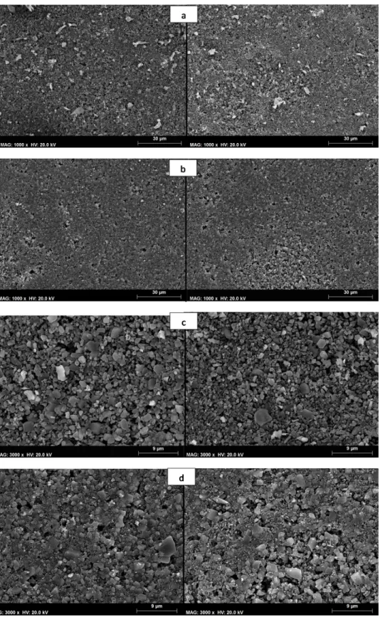
IGURESFigure 2.1 Experimental set-up used for the ultrafiltration experiments ... 14 Figure 2.2 Cross section view coated (a) 1st generation and (b) 2nd generation membranes .... 16 Figure 2.3 Comparison between two different membrane surface sections; Top view of the 1st
generation membrane (a and c) and 2nd generation membranes (b and d) at 1000 and 3000
magnifications... 17
Figure 2.4 C 1s (a) and Si 2p (b) core level spectra for 1st generation (blue) and 2nd generation
(orange) membranes ... 19
Figure 2.5 Depth variation of: (a) carbon A.C. (%) and (b) silicon A.C. (%) for 1st generation
membrane (♦) and 2nd generation membrane (▲). ... 20 Figure 2.6 Characterization of the feed and permeate samples taken during with the filtration
experiments of sunflower oil wastewater using 1st and 2nd generation membranes in terms of (a)
total solids, (b) total suspended solids, (c) chemical oxygen demand (COD) and (d) oil and grease ... 21
Figure 3.1 Scheme of the pilot filtration unit with cleaning devices (BP—Backpulse and BW—
Backwash) used to treat the real olive mill wastewater in different operation modes (recirculation and concentration tests). ... 28
Figure 3.2 Variation of transmembrane pressure (TMP) with increase of controlled permeate flux.
... 32
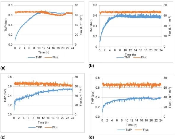
Figure 3.3 TMP and flux profiles obtained in the different assays: (a) test 1; (b) test 2; (c) test
3;(d) test 4 ... 33
Figure 3.4 Percent recovery of the permeate flux per transmembrane pressure applied
(Jv/ΔTMP)/( Jv/ΔTMP)clean with different cleaning protocols performed after the membrane filtration
assays: (a) test 1; (b) test 2; (c) test 3; (d) test 4. ... 38
Figure 3.5 Transmembrane pressure (TMP) and permeate flux profiles obtained in the
concentration test. ... 40
Figure 3.6 Percent rejection of total suspended solids, oil and grease, chemical oxygen demand
(COD), total organic carbon (TOC) and total solids—Concentration test. ... 41
Figure 4.1 Schematic representation of the experimental setup; 1, feed tank; 2, pre-filter; 3, high
pressure pump; 4, pressure gauge; 5, spiral-wound membrane element; 6, permeate tank; 7, retentate valve; 8, flowmeter ... 49
Figure 4.2 Variation of normalized permeate flux (Jv/Jv, 0) with the volume reduction factor (VRF)
throughout nanofiltration assays NF1 29), NF2 45), NF3 58), and NF4 (VRF-81) ... 53
Figure 4.3 Total rejection and adsorption percentages determined in NF1 29), NF2
(VRF-45), NF3 (VRF-58), and NF4 (VRF-81) assays for total suspended solids (a), total solids (b), total organic carbon (c), chemical oxygen demand (d), oil and grease (e), and total phenols (f), taking into account the concentration of feed wastewater and total permeate ... 55
Figure 4.4 Variation of the rejection of total suspended solids, total solids, total organic carbon,
oxygen demand, oil and grease, and total phenols with the volume reduction factor (VRF) throughout the longest assay (NF4; VRF-81) ... 57
Figure 4.5 Sensitivity analysis: impact of the cost of water, retentate disposal, energy, and
membrane replacement on total operation cost for the 5 month treatment at VRF-34... 64
Figure 5.1 Flow chart depicting the basic experimental procedures followed for sol deposition
process with titania. ... 70
Figure 5.2 Flow chart depicting the basic experimental procedures followed for sol deposition
process and designation of membranes with silicon dioxide and titanium dioxide. ... 72
Figure 5.3 Setup used to test the membrane filtration performance. ... 74 Figure 5.4 Degradation and adsorption of methylene blue using the unmodified substrates and:
(a) membranes modified with sol-gel TiO2, (b) a combination of sol-gel and Degussa P25 TiO2
nanoparticles and (c) a combination of sol-gel SiO2 and Degussa P25 TiO2 nanoparticles ... 76 Figure 5.5 Removal efficiency of the most promising membranes after different photocatalytic
assays. ... 81
Figure 5.6 Reproducibility of methylene blue degradation after different assays using two different
commercial membrane batches (Membrane I and Membrane II) modified with a combination of SiO2 and TiO2. ... 82 Figure 5.7 Photocatalytic degradation of methylene blue during a long term assay with the
membrane SiO2-TiO2 (L3). Error bars correspond to duplicate experiments. ... 83 Figure 5.8 Top view of SEM images of control membranes and most promising modified
Figure 5.9 Cross-section of SEM images of control membranes and most promising modified
membranes (magnification 200). ... 85
Figure 5.10 Representation of mean pore size area and pore density estimated with the software
ImageJ in two different membrane zones (denoted Z1 and Z2) for the most promising membranes. ... 88
Figure 5.11 Concentration of methylene blue (MB) in the permeate during membrane filtration
conducted in the absence (filtration) and presence of ultraviolet (UV) radiation (filtration+UV) obtained with the (a) unmodified membrane and the (b) modified membrane SGSi ... 91
Figure 6.1 Submerged membrane photocatalytic reactor, developed and tested to treat olive mill
wastewaters ... 95
Figure 6.2 Characterization of the olive mill wastewater in terms of total solids, total dissolved
solids, total suspended solids, total organic carbon, chemical oxygen demand and phenolic compounds ... 98
Figure 6.3 Determination of the optimal transmembrane pressure ... 100 Figure 6.4 Variation of the permeability of the membranes in the four filtration tests ... 101 Figure 6.5 Percent removals of chemical oxygen demand, total organic carbon and phenolic
compounds in the tests C.F, C.UVF, M.F and M.UVF ... 103
L
IST OFT
ABLESTable 1.1 Composition of olive mill wastewaters ... 2
Table 2.1 Characteristics of the tubular SiC membranes tested ... 15
Table 2.2 Predicted measurements for two sections (S1 and S2) of the 1st generation and 2nd
generation membranes obtained based on the SEM magnification of 1000 ... 18
Table 2.3 Atomic concentration percentages of the characteristic elements found on the surface
of the analyzed samples and C/Si ratio ... 19
Table 2.4 Hydraulic permeability of 1st and 2nd generation membranes ... 21 Table 2.5 Percentage removal of the quantified parameters obtained by membrane filtration of
sunflower oil wastewater using 1st and 2nd generation membranes ... 22 Table 3.1 Characteristics of the silicon carbide (SiC) membrane module used. ... 29 Table 3.2 Characterization of the real olive mill wastewater samples collected and limits imposed
by legislation ... 29
Table 3.3 Permeate flux and flux maintenance strategies applied in the different filtration tests.
... 30
Table 3.4 Comparison of ∆TMP and effectiveness (ᅍ) of backpulses (test 2) and backwashings
(test 3 and test 4) as flux maintenance strategies. ... 34
Table 3.5 Percent total rejection and adsorption/deposition of total solids, total suspended solids,
chemical oxygen demand (COD), total organic carbon (TOC) and oil and grease ... 35
Table 3.6 Characterization of feed and permeate in terms of total solids, total suspended solids
(TSS), chemical oxygen demand (COD), total organic carbon (TOC) and oil and grease in tests 1–4. ... 36
Table 3.7 Characterization of the olive mill wastewater used in the concentration test in terms of
total solids, total suspended solids, chemical oxygen demand (COD), total organic carbon (TOC) and oil and grease. ... 40
Table 4.1 Physico-chemical characterization of the raw olive mill wastewater ... 47 Table 4.2 Comparison of concentration values determined for the parameters addressed in the
Table 4.3 Volumes of feed and retentate, respective volume reduction factors (VRFs) as well as
initial fluxes obtained in the different nanofiltration studies carried out ... 49
Table 4.4 Volatile compounds identified in permeate and feed samples of the longest assay (NF4;
VRF-81) by GC-MS, respective identifications similarities with the database as well as their molecular weight (MW) ... 58
Table 4.5 Economic feasibility study for the nanofiltration treatment of olive mill wastewater,
considering different plant capacities, defined according ... 62
Table 5.1 Molar ratio compositions followed for the preparation of different membranes with
photocatalytic properties. ... 71
Table 5.2 Methylene blue degradation, methylene blue adsorption and first constant angle values
obtained for the different membranes. ... 77
Table 5.3 Pseudo-first-order kinetic parameters for the methylene blue degradation. ... 80 Table 5.4 Image J analysis of two SEM images from different membrane zones Z1 and Z2
(threshold value: 35; magnification: 3000; membrane area: 1365 µm2). ... 87 Table 5.5 Hydraulic permeability and percent (%) rejection of methylene blue during membrane
filtration (MF) conducted in the absence and presence of ultraviolet (UV) radiation obtained with the unmodified membrane and the modified membrane SGSi-D (L3). ... 90
Table 6.1 Description of the six tests performed in the submerged photocatalytic membrane
reactor ... 98 Table 6.2 Volatile compounds detected in the feed samples ... 99
Table 6.3 Removals of total solids, total suspended solids and total dissolved solids after 4h of
filtration ... 102
Table 6.4 Percent of similarity and removal of the organic volatile compounds detected in the
1
1
1
1
IIII
NTRODUCTION
NTRODUCTION
NTRODUCTION
NTRODUCTION
1.1 STATE OF THE ART
Mediterranean countries and olive oil production
The traditional Mediterranean diet, known for being a rich and healthy diet, uses olive oil as its main source of fats. Also olive oil is rich in specific phenolic compounds, that have been reported as very beneficial for human health [1]. Mediterranean Countries are responsible for 95% of the olive oil produced in the world, producing about 1.7 million tons of olive oil per year [2]. The production of olive oil employs a very significant number of people and is one of the main industrial activities in these Countries. Moreover, olive oil production has been expanding outside the Mediterranean area and is now an emerging activity in countries such as China, the USA, Australia and the Middle East [3].
Olive mill wastewaters
Due to the worldwide growth of the olive oil industry, the treatment and discharge of the produced wastewaters is becoming a global concern [4]. In the Mediterranean region, there is an annual discharge of 30 million m3 olive mill wastewater into the environment [5, 6].
Olive mill wastewaters are highly charged effluents produced by olive oil industries [4], representing an environmental hazard if not treated properly. Table 1.1 shows some of the main characteristics of olive mill wastewaters reported in the literature.
Table 1.1 Composition of olive mill wastewaters
Physico-chemical parameters Literature Values
Total solids (mg/L)
99700 [7] 44000 [8] 63300 [9] 42400 – 101500 [10]
Total suspended solids (mg/L) 4520 [7] 2700 [8]
Total volatile solids (mg/L) 87200 [7] 33600 [8] Total organic carbon (mg/L) 34200 [11] 39800 [7]
Chemical oxygen demand (mg/L O2)
93000 [7] 67000 [8] 103000 [12] 178000 [13] 130000 [9] 89200 – 101500 [10]
Biochemical oxygen demand (mg/L O2)
46000 [7] 55000 [8] 22800 – 23200 [10] Total nitrogen (mg/L) 768 [7] 620 [8] 790 [12] 860 [9] pH 4.8 [7] 4.93 [8] 4.8 [12] 5 [9] 5.4-5.5 [10] Conductivity (mS/cm) 18 [7] 18 [8] 10 [9] Carbohydrates (mg/L) 16100 [7] 4800 [8] 4700 [12] Lipids (mg/L) 12000 [7] 2400 [13] Polyphenols (mg/L) 10700 [7] 980 [8] 3800 [12] Sodium (mg/L) 200 [13] 300 [7] Calcium (mg/L) 200 [13] 270 [7] Magnesium (mg/L) 92 [13] 44 [7] Iron (mg/L) 18.3[13] 120 [7] Copper (mg/L) 2.1 [13] 6 [7] Manganese (mg/L) 1.5 [13] 12 [7]
These effluents present low pH and a high concentration of solids, oil and organic compounds such as organic acids, lipids and alcohols [5, 14].
Due to the high concentration of organic matter and phenolic compounds, that are responsible for the dark color and antimicrobial and phytotoxic effect of olive mill wastewaters, the traditional biological treatment becomes difficult [15-17], being necessary to study and develop new treatment processes.
Common practices and treatment processes
Land spreading and evaporation in lagoons are the most common practices of olive mill wastewater management [11, 18]. However, this practice may lead to serious impacts on environment due to the high acidity, antibacterial and phytotoxic properties of these effluents [19, 20]. On the other side, evaporation on lagoons has serious drawbacks such as low efficiency and sludge-disposal problems since it can only concentrate olive mill wastewater until 70-75% of its initial volume with no degradation of organic matter [21]. Moreover, this method requires a large area, produces bad odors, and may lead to pollutant infiltration to ground water and insect proliferation [22].
Conventional wastewater physical and chemical treatment approaches include coagulation, flocculation, sedimentation, and flotation. Coagulation and flocculation are commonly used treatment processes in water and wastewater treatment in which chemical compounds are added to the water in order to destabilize the colloidal materials/stable oil emulsified droplets and cause the small particles to agglomerate into larger settleable/floatable flocs that may be subsequently removed by sedimentation and flotation. This process was been studied to treat olive mill effluents with removals of chemical oxygen demand and phenolic compounds of 90% and 95%, respectively [18]. Flotation was also studied to integrate the treatment of olive mill wastewaters [10] and consists in increasing the density difference between the continuous and dispersed phases by adding a gas into the oily wastewater to promote the formation of air–solid or air–oil agglomerates with increased buoyancy, being used in the treatment of dispersed and emulsified oil in wastewaters.
Biodegradation is also an approach that has been studied for the treatment of olive mill effluents. However, the high concentration of organic matter and phenolic compounds has been described to hinder this process [15-17].
This problem and the need to achieve higher quality effluents have promoted the development of new processes for oily wastewater treatment such as membrane processes.
Pressure-driven membrane processes to treat olive mill wastewaters
The use of membrane processes for treatment of olive mill wastewater has been studied since the 1990s, having undergone a large increase at the beginning of this decade while the study of other simple processes tended to decrease [5].
It has gained interest due to more stringent regulations, translated into a demand for water with high quality as well as the increased awareness and need to reuse water [23, 24]. Membrane processes have been reported as highly efficient to treat stable emulsions, avoid chemical addition, produce a small amount of solids requiring disposal as well as achieve high chemical oxygen demand (COD) removal and overall higher quality of permeate produced. Moreover, these systems have a small footprint, easy operation and are easily combined with other treatment processes [25, 26].
Microfiltration, ultrafiltration and nanofiltration are widely studied as an integral part of the treatment of this effluent. Studies show that microfiltration can remove high extents of total suspended solids and oil and grease but the dissolved fraction of organic carbon needs a further treatment to be removed at satisfactory levels [27, 28]. Depending on the membrane characteristics, ultrafiltration can remove 20-50% of the total organic carbon [29, 30], 30-40% of chemical oxygen demand [31, 32] and can achieve removals near 50% of phenolic compounds [29]. If nanofiltration is used, removals higher than 80% of the mentioned parameters can be obtained [31, 32]. A work performed at industrial scale involving membrane processes allowed removals of 98% of organic load [33].
1.1.4.1 Ceramic membranes
The use of ceramic membranes recently increased, particularly in the treatment of industrial wastewaters, including food, pulp and paper, textile, petrochemicals and pharmaceutical industries [34]. Due to their advantages compared with polymeric membranes, such as better thermal stability, mechanical resistance and chemical resistance, ceramic membranes can be applied in extreme aggressive environmental conditions [35]. These properties allow for a better control of membrane fouling since higher pressures can be employed in backwashes and cleanings can be performed with stronger chemicals, without compromising the membrane lifetime [36].
Among several materials, alumina is often used as a support material for ceramic membranes due to its smooth surface, in contrast to other materials, and since it is fairly inert. On the other hand, it can be easily deposited in macroporous supports. However, alumina does not present high enough chemical or mechanical stability when subject to severe conditions. Silicon carbide (SiC) is a promising alternative material since it presents better resistance to chemicals, thus presenting advantages when strong and repeated cleanings are required [37, 38]. Even when
compared with polymeric and other ceramic membranes such as titania or zirconia, silicon carbide membranes present higher hydrophilicity and lower fouling tendency [39].
Ceramic membranes have been studied to treat olive mill wastewaters. Even though microfiltration using a TiO2 membrane could not significantly remove phenolic compounds, a
nanofiltration with a membrane made of the same material retained nearly 50% of phenolic compounds and 20% of the total organic carbon. However, this efficiency is low when compared with the results reported for polymeric membranes: in this case, polyphenols and total organic carbon can be removed in percentages higher than 90% [40]. On the other hand, microfiltration ceramic membranes can be extremely efficient for the removal of total suspended solids and oil and grease, achieving removals higher than 99% [27, 41, 42].
1.1.4.2 Membrane fouling
The development of fouling on the membrane is the main drawback of membrane processes, being a limiting factor in the use of this technology, particularly at industrial scale. Fouling is caused by the adsorption and accumulation of rejected oil, suspended solids and other components of the wastewaters on the membrane surface and within the intrapore structure [39]. The main consequence of fouling is flux decline, which leads to a decrease of permeate flux being higher pressures needed to maintain flux, with consequent higher energy consumption and operation costs [23].
1.1.4.2.1 Membrane cleaning and flux maintenance strategies
Although chemical cleaning methods are the most widely used in membrane cleaning, the chemical agents used may damage the membranes and reduce their lifetime. Furthermore, chemical cleaning methods generate waste solutions and have high costs associated [43]. The first approach that must be consider is to work below the critical flux which, minimizing the development of fouling [44]. Besides operating under optimum permeate flux conditions, different cleaning systems can be applied as flux maintenance strategies e.g. backpulses (BP), backwashes (BW), chemically enhanced backwashing (CEB) and cleaning in place (CIP). The goal of backpulses is to loosen membrane fouling through a negative transmembrane pressure (TMP) which is sufficient to penetrate into the inner channels. A great advantage of using backpulses is the low amount of permeate lost due to the short duration of the pulses. Frequent pulses are preferable because the initial impact of the pulse is considered determinant. When using ceramic membranes the backpulses are exceedingly efficient due to the low resistance in the porous matrix and due to the strength of the element. Nevertheless, frequent pulses need to be considered in the design of the membrane plant, as pressure oscillations may destabilize the
system. Backwashes use the shear from a reversed flowrate (the permeate is forced through the membrane towards the retentate side).
Some authors have already described the effect of backpulses and backwashes strategies in the development of fouling and, consequently, in the permeability of the membrane. The effect of backpulses and backwashes in the microfiltration of oil-in-water emulsions with ceramic membranes was already studied and reported. Results show that these strategies are efficient in fouling mitigation with no impact in the oil rejection [41, 42, 45]. From an economic point of view, a study comparing the microfiltration of emulsified crude oil with and without backpulses revealed that the process without backpulses is not economically viable when compared to conventional treatment methods. However, the same operation with regular backpulses resulted in lower costs of treated water when compared with conventional methods [46].
Despite the great advantages of performing backpulses and backwashes in order to minimize fouling, when the transmembrane pressure drops more than 15% compared to the initial transmembrane pressure after a backpulse or a backwash, chemical cleaning should be performed [47]. During the cleaning procedure, the filtration process is stopped and chemical solutions (e.g. sodium hydroxide, ultrasil® and citric acid solutions) are used to clean the membrane and remove chemically reversible fouling. While backpulses and backwashes are automatically carried out, chemical cleaning requires the presence of an operator and may take several hours. The frequency of cleanings and the type of chemicals to employ depend on the characteristics of the water but may vary between one time per week or per month [48, 49]. The composition of the cleaning solutions used should thus be defined in order to determine which chemicals and temperature levels should be employed to restore the permeability after filtration of different wastewaters. Pre-treatment of wastewater is often proposed to minimize the frequency of these procedures.
1.1.4.2.2 Modification of the membrane surface
Membrane performance, especially when treating wastewaters with high content of oil and grease, which is the case of olive mill wastewaters, is affected by surface hydrophilicity of the membrane. Hydrophobic solutes in the wastewater, such as emulsified oils, readily foul such membranes via strong hydrophobic interactions [50]. Therefore by improving the hydrophilicity of the membrane it is possible to reduce the development of fouling.
Several studies describe ways to increase the hydrophobicity of the membrane by modifying its surface, focusing on the use of nanoparticles. The use of nanoparticles enables the production of desired membrane structures and functionalities that allow a high degree of control over membrane fouling and achieving a high quality of permeate [51].
Among other materials, titanium dioxide (TiO2) is the most studied due to its particular
advantages, that includes its easy availability, low cost and high chemical stability in addition to its high oxidant capacity of the photogenerated holes, which gives a high photocatalytic activity to this nanoparticle [52]. Several publications report the superhydrophilic properties of membranes when TiO2 is incorporated in their structure, especially in the presence of UV radiation
[53-57]. In fact, TiO2 surfaces become superhydrophilic with a contact angle of less than 5◦ when
exposed to UV-light [58], originated by chemical composition changes on the surface [59]. The photocatalytic activity of TiO2 has been also widely reported. TiO2 is able to degrade a variety
of organic compounds in the presence of UV radiation [52]. The photocatalytic process starts with the generation of conduction electrons and valence band holes as a consequence of the activation of TiO2 by UV radiation with energy higher than its band gap energy. The photo induced hole can
oxidize a donor molecule adsorbed on the TiO2 surface and the electron in the conduction band
can reduce an acceptor molecule. Thus, a variety of possible reactions can occur, that lead to the generation of superoxide and hydroxyl radicals. These radicals attack organic substrates initiating the process of photocatalytic oxidation [60, 61].
The use of TiO2 photocatalysis to enhance the treatment of olive mill wastewaters has already
been assessed. Badawy et al [62] studied the possibility of improving the biodegrability of this effluent for further treatment using TiO2 photocatalysis obtaining positive results. The degradation
of several phenolic compounds typically found in these wastewaters can also be achieved with TiO2 photocatalysis [63], as well as the reduction of colored molecules and chemical oxygen
demand [64].
1.1.4.3 Photocatalytic membrane reactors
Photocatalytic reactors have attracted attention for water and wastewater treatment since, using this technology, refractory organic and toxic pollutants present in water sources can be degraded into simple and harmless inorganic molecules, minimizing the use of chemicals and avoiding sludge production and its disposal. However, photocatalytic reactors present some drawbacks, including the catalyst-recovering step from the solution at the end of operation, that still need to be addressed before application at large scale [65-67]. Membrane technology can improve the implementation of photocatalysis by assuring the separation of the photocatalyst from the treated water [68].
TiO2 photocatalysis can be performed in photocatalytic reactors with the photocatalyst in
suspension or immobilized on a carrier and several schemes of photocatalytic membrane reactors have been described and extensively reviewed elsewhere [69, 70]. Regarding the membrane location, it can be placed outside in an external loop [71, 72] or submerged inside [73, 74] the photocatalytic reactor. In this case, the system is defined as submerged photocatalytic membrane
reactor. In the literature, most of the work published regarding the removal of organic compounds from water using submerged photocatalytic membrane reactors was performed with the photocatalyst in suspension.
When TiO2 is in suspension, loss of TiO2 due to adsorption to the system is expected [75].
Moreover, as previously mentioned, a further step is required in order to separate it from the treated water [69]. This step may also involve the use of a membrane. In addition, TiO2 in
suspension was reported to contribute to the fouling appearance on the membrane surface [76-78].
In this context, the immobilization of TiO2 on the membrane surface is the best solution to combine
the two processes, photocatalysis and membrane separation. Moreover, the immobilization of TiO2 on the membrane surface showed to be useful in the mitigation of fouling [79-83].
The immobilization of TiO2 on the membrane surface may be achieved by using a sol-gel
technique. The sol-gel process consists of a chemical process (hydrolysis-condensation) involving a metal alkoxide (or semi metal) precursor with itself creating a three-dimensional continuous solid linkage, through a basic or acid catalysis process [84]. This process has been proposed to synthetize TiO2-based photocatalysts with high oxidation efficiency as well as for
TiO2 immobilization in a large number of supports to control their porosity [85, 86].
1.2 OBJECTIVES
The main objectives of the work developed and presented in this thesis was: 1 - to enhance the treatment of olive mill wastewaters using different membrane processes and; 2 - the development of a novel hybrid photocatalytic membrane reactor.
A silicon carbide ultrafiltration ceramic membrane was chosen to perform this work due to the particular advantages of this material. This ceramic membrane was thoroughly characterized in terms of surface composition and morphology.
Two strategies were followed to improve the removal of the dissolved compounds to values acceptable by legislation [87] and minimize fouling: (a) pilot scale treatment by ultrafiltration after optimization of backpulses and backwashes, followed by nanofiltration and (b) development of photocatalytic membranes by sol-gel.
The final goal of this work was to develop a novel submerged photocatalytic membrane reactor that can be easily scaled up to test the photocatalytic membranes developed.
1.3 THESIS OUTLINE
The present work is, thus, organized in seven chapters.
Chapter 1 consists in a brief revision of the state-of-the-art, focused in the problem of olive mill
wastewater treatment. Membrane processes (described in Chapters 2 to 4) and the development of hybrid systems combining membrane filtration with TiO2 photocatalysis (described in Chapters 5 and 6) were addressed as these processes are an important part of the solution to overcome
this problem.
Chapter 2 describes the exhaustive characterization and comparison in terms of surface
composition, morphology and filtration performance of a commercially available membrane with a novel silicon carbide membrane produced by LiqTech with a single top layer. In this work, this membrane was validated to treat oily wastewater and proved to be extremely promising at laboratory scale to remove oil and grease and total suspended solids.
Chapter 3 presents the work developed at pilot scale using a tubular silicon carbide membrane
to treat olive mill wastewaters under controlled constant permeate flux. The filtration conditions were evaluated and optimized in terms of the selection of the permeate flux and flux maintenance strategies employed—backpulses and backwashes—in order to reduce fouling formation. Membrane filtration using silicon carbide membranes was proven to be an effective alternative to dissolved air flotation and can be applied efficiently to remove total suspended solids and oil and grease from olive mill wastewaters. However, and even though good percent removals were obtained, the concentration of chemical oxygen demand was considerably above the legislated limit (125 mg O2 L-1) [87].
To overcome this problem, two different strategies were used: (a) further processing by nanofiltration using the polymeric membrane Desal 5DK (Chapter 4) and (b) a treatment using a hybrid photocatalytic membrane reactor (Chapter 6) after the development of effective and reproducible photocatalytic membranes (Chapter 5).
Chapter 4 presents the results obtained when nanofiltration was performed at pilot scale to treat
an effluent similar to the permeate resultant from ultrafiltration. Considerably high rejections of total suspended solids, total organic carbon, chemical oxygen demand, as well as oil and grease were attained. Only the concentration of total phenols and chemical oxygen demand in the permeates produced could not comply with European legislation [87] for discharge into water courses.
In Chapter 5, novel coatings comprising titanium dioxide (TiO2), silicon dioxide (SiO2) and silicon
carbide (SiC) semiconductors, were deposited over silicon-carbide substrates to develop photocatalytic membranes. The most promising membrane in terms of photocatalytic effectiveness and reusability was modified with SiO2 obtained by sol-gel combined with Degussa
light. Results confirmed the photocatalytic activity of the membrane combined with filtration, showing that the modified membranes have a high potential to degrade organic contaminants. The work presented in Chapter 6 consists in the olive mill wastewater treatment using the photocatalytic membrane developed in Chapter 5 in a new conceived and assembled submerged membrane photocatalytic reactor that can be easily scaled up. Results proved the photocatalytic activity of the membrane and the effectiveness of the new proposed treatment process.
Chapter 7 summarizes the main results obtained in the studies presented in this thesis and
provides a discussion integrating the results obtained in the different developed works. Future work and perspectives are also discussed.
2
2
2
2
M
M
M
M
ORPHOLOGICAL
ORPHOLOGICAL
ORPHOLOGICAL
ORPHOLOGICAL
,,,,
CHEMICAL SURFACE AN
CHEMICAL SURFACE AN
CHEMICAL SURFACE AND FILTRATION
CHEMICAL SURFACE AN
D FILTRATION
D FILTRATION
D FILTRATION
CHARACTERIZATION OF
CHARACTERIZATION OF
CHARACTERIZATION OF
CHARACTERIZATION OF A NEW SILICON
A NEW SILICON
A NEW SILICON CARBIDE MEMBRANE
A NEW SILICON
CARBIDE MEMBRANE
CARBIDE MEMBRANE
CARBIDE MEMBRANE
Published as: M.C. Fraga, S. Sanches, V.J. Pereira, J.G. Crespo, L. Yuan, J. Marcher, M.V.M. de Yuso, E. Rodríguez-Castellón, J. Benavente, Morphological, chemical surface and filtration characterization of a new silicon carbide membrane, Journal of the European Ceramic Society 37(3) (2017) 899-905.
The author M.C. Fraga was directly involved in planning and executing the study of the morphology of the membrane and the filtration tests, as well as on the data analysis, discussion and interpretation and manuscript elaboration.
2.1 SUMMARY
A new silicon carbide ceramic membrane consisting of a unique top layer on a silicon carbide support for application in oily wastewaters filtration was produced and characterized in terms of morphology and chemical surface composition by scanning electron microscopy and X-ray photoelectron spectroscopy measurements. The manufacturing process of this new membrane allows time and economic savings when compared with a two layers membrane previously obtained. The new membrane has a smooth top layer with controlled porosity and a higher permeability compared to already developed commercial membranes. Moreover, it is extremely efficient to remove total suspended solids as well as oil and grease and, consequently, it can be applied to effective treatment of industrial oily wastewaters.
2.2 INTRODUCTION
Oily wastewaters are generated by different industries. In particular, vegetable oil wastewater from the food industry shows high content in solids, chemical oxygen demand as well as oil and grease components [88-90]. Numerous techniques can be employed for the removal of emulsions: conventional physical and chemical treatment approaches include gravity separation and skimming, coagulation, flocculation, sedimentation, and flotation. However, these methods present disadvantages such as low efficiency in the treatment of stable emulsions, high sludge production, high operation costs and need of chemical addition [91].
Membrane processes such as microfiltration, ultrafiltration, nanofiltration and reverse osmosis are increasingly being applied for treating oily wastewaters, metal polluted waters and desalting processes [91]. Among other advantages, membrane filtration processes present high efficiency for oil removal, moderate energy cost and compact design compared with the conventional treatment methods [42]. However, membrane fouling caused by the deposition (or adsorption) of
solution particles and solutes on the membrane surface and pore walls, is the main factor limiting the application of membranes filtration processes, since it reduces the permeate flux and impairs separation properties [92]. Consequently, frequent membrane cleaning protocols need to be applied sequentially which partially affects the selection of a particular membrane.
Commercial synthetic membranes are produced from two distinct classes of material: polymers consisting of organic material (e.g. polysulfone, regenerated cellulose, poliamide and polyvynilfluoride) or inorganic materials (mainly ceramics) [93]. Ceramic membranes have advantageous properties when compared to polymeric membranes such as higher mechanical, chemical and thermal stability, which are basic requirements for adequate cleaning protocols and, consequently, higher membrane lifetime [9-10]. Furthermore, depending on the used materials, they can present a higher hydrophilicity [39, 94, 95].
The improvement of membrane hydrophilicity and fouling reduction through the use of membrane coatings with nanoparticles are currently a challenge [96]. Silicon carbide (SiC) ultrafiltration (UF) membranes exhibit high hydrophilic membrane surface, high porosity, and rather uniform pore size distribution [97, 98]. Higher membrane fluxes, lower fouling, and longer membrane lifetime are, therefore, expected using these membranes [39]. Further membrane structure modifications could still be tested to reduce production time and costs, while maintaining the membrane efficiency.
In this work, a new silicon carbide ceramic membrane (with a single retentive layer above the substrate) was developed (referred in this work as 2nd generation membrane) and compared with
a previously developed and commercialized silicon carbide membrane with two layers above the substrate (1st generation membrane). These membranes were characterized in terms of
morphology and chemical composition by scanning electron microscopy and X-ray photoelectron spectroscopy measurements. Both membranes were also tested with respect to their possible application in the treatment of vegetable (sunflower) oil wastewaters. Their efficiency was evaluated in terms of their effectiveness to remove solids, chemical oxygen demand and oil and grease.
2.3 MATERIAL AND METHODS Silicon carbide membranes
Two different 100% silicon carbide membranes (1st generation and 2nd generation) were
manufactured by LiqTech. The membranes were prepared in tubular configuration and were used for surface characterization and to perform filtration tests of sunflower oily wastewater.
The 1st generation membrane consists of a highly porous silicon carbide substrate, prepared by
on the substrate by high temperature thermal treatment (T > 20000C) in an argon atmosphere,
followed by an oxidation step. Subsequently, the final selective layer is coated on the top of this layer and a second sintering takes place (T > 18000C) to achieve the appropriate pore size.
Considerable evidence suggested that the surface properties of the support (roughness, inhomogeneity and defect density) influence the uniformity and the integrity of the coated membrane. Therefore, a new procedure was developed to produce a new membrane (2nd
generation membrane), in which a single top layer is applied directly on the substrate (without the intermediate membrane layer present in the 1st generation membrane). The advantage of this
new procedure is the fact that one firing step can be eliminated in the production process, reducing significantly both the production time and the manufacturing costs (approximately 30%). Since sintering the membrane layer is the manufacturing bottleneck, this process change may increase a factory capacity by 100%. Moreover, the microstructure and the surface of the substrate is better controlled, since the whole process has one less high temperature firing, thus, making the final layer smoother and with less defects.
Scanning electron microscopy (SEM)
The surface and cross section of 1st and 2nd generation membranes were characterized by scanning
electron microscopy (SEM) using a field emission gun scanning Electron Microscope (FEG-SEM from JEOL) model JSM7001F with an acceleration voltage of 15kV. The samples were placed in a sample holder with carbon double sided adhesive tape and were then coated with a film of chromium using a Quorum Technologies Q150T ES.
The SEM images were processed using the ImageJ software developed by Wayne Rasband (http://rsb.info.nih.gov/ij/docs/intro.html), a public domain Java image processing program that superseded the Image Macintosh software developed by the National Institute of Health (USA).
X-ray photoelectron spectroscopy (XPS)
The chemical characterisation of the surface of the studied membranes was performed by XPS. A Physical Electronics spectrometer (PHI 5700) with X-ray Mg Kα radiation (300W, 15 kV, 1253.6
eV) as the excitation source was used for these measurements. High-resolution spectra were recorded at a given take-off angle of 45º by concentric hemispherical analyser operating in the constant pass energy mode at 29.35 eV, using a 720 µm diameter analysis area. Under these conditions, the Au 4f7/2 line was recorded with 1.16 eV FWHM at a binding energy of 84.0 eV.
Each spectral region was scanned several sweeps until a good signal to noise ratio was observed. The pressure in the analysis chamber was maintained lower than 5×10⁻⁶ Pa. The software
background was subtracted from the signals. The recorded spectra were fitted using Gauss– Lorentz curves according to the methodology described in detail elsewhere [18], in order to determine more accurately the binding energy (BE) of the different element core levels. Atomic concentration percentages of the characteristic elements on the sample surfaces were determined taking into account the corresponding area sensitivity factor [18] for the different measured spectral regions.
In order to eliminate possible surface contamination (sample manufacture or environmental contamination), measurements using a non-invasive technique such as angle resolved XPS (ARXPS) using five values of the take-off angle (15°≤ α ≤ 75°) were also performed, which provide chemical information for depth ranging, approximately, between 2.5 nm and 9.5 nm [99].
Membrane filtration: Experimental set-up and ultrafiltration procedure
A comparison of the performance of 1st and 2nd generation membranes was carried out using a
laboratory scale filtration unit operated with total recirculation of permeate and retentate due to volume constrains. Figure 2.1 shows a scheme of the filtration system while the characteristics of the membranes used are indicated in Table 2.1.
Figure 2.1 Experimental set-up used for the ultrafiltration experiments
The filtration unit is composed of a feed vessel, a high-pressure pump, a valve to regulate pressure on the retentate side, three pressure sensors and the membrane housing (LiqTech, Denmark). Pressure readings of permeate, feed, and retentate were acquired in real-time and used for the determination of transmembrane pressure (TMP).
Table 2.1 Characteristics of the tubular SiC membranes tested
The hydraulic permeability of the 1st and 2nd generation membranes was determined by setting
different permeate fluxes and reading the corresponding pressure values to further calculate transmembrane pressure. For both membranes, five measurements were performed for each permeate flux set to obtain an average value. Five liters of real sunflower oil wastewater sample were then filtered using 1st and 2nd generation membranes. The experiments were carried out
with a constant transmembrane pressure of 1.5 bar and a cross flow velocity of 0.5 m/s. Samples of feed were taken in the beginning and in the end of each experiment while samples of retentate and permeate were taken in the end of the experiments to quantify total solids, chemical oxygen demand as well as oil and grease concentrations using the methods detailed below. Samples were stored at 4°C until analysis.
Analytical methods
Permeate, feed, and retentate samples from cross-flow filtration experiments were characterized in terms of the following parameters using well established methods [100]: total solids (Standard Method 2540B), total suspended solids (Standard Method 2540D), chemical oxygen demand (Standard Method 5220) and oil and grease (Standard Method 5520C).
Length (mm) 305
Number of channels 31
Channel diameter (mm) 3
Cross-section area of each channel (m2) 7.1 x 10⁻⁶ Total cross-section area (m2) 2.2 x 10⁻⁴
2.4 RESULTS AND DISCUSSION Membrane characterization
Cross sections and surfaces of 1st and 2nd generation membranes were analyzed by scanning
electron microscopy (SEM). Figure 2.2 shows the cross-section of both samples where the presence of two different layers on the support structure can be observed for the 1st generation
membrane (Figure 2.2 a), while a single layer of 60 µm exists in the case of the 2nd generation
membrane (Figure 2.2 b). This difference could affect the solution flow across the membranes, depending on the layers’ structure.
Figure 2.2 Cross section view coated (a) 1st generation and (b) 2nd generation membranes
Figure 2.3 shows that even though the size of silicon carbide nanoparticles is varied, different
sections of the same membrane are very similar. Two different membrane sections of each membrane were processed using the ImageJ software for the ×1000 images magnifications obtained. The original SEM images composed of 256 grey levels were analysed using ImageJ, spatially scaled, their total membrane surface area was calculated and the images were then binarized.
Figure 2.3 Comparison between two different membrane surface sections; Top view of the 1st generation membrane (a and c) and 2nd generation membranes (b and d) at 1000 and 3000 magnifications.
The area measurements obtained, calculated pore density (number of pores divided by area of membrane), porosity (area of pores divided by area of membrane), circularity (equation 2.1), and Feret’s diameter (the longest distance between any two points along the selection boundary) [101] are presented in Table 2.2 for the 1st (a) and 2nd (b) generation membranes.
(Equation 2.1)
Table 2.2 Predicted measurements for two sections (S1 and S2) of the 1st generation and 2nd generation membranes obtained based on the SEM magnification of 1000
Predicted parameters 1st Generation 2nd Generation
Porosity (%) 3.274 2.740 2.536 2.844
Number of pores 8872 8340 8329 8506
Pore density (µm-2) 0.687 0.646 0.645 0.659
Mean Pore Area ± Standard
Deviation (µm2) 0.048 ± 0.088 0.042 ± 0.074 0.040 ± 0.114 0.043 ± 0.109
Minimum Pore Area (µm2) 0.009 0.009 0.009 0.009
Maximum Pore Area (µm2) 1.661 1.458 3.884 1.996
Total Pore Area (µm2) 422.762 353.780 327.508 367.177
Average Circularity 0.869 ± 0.203 0.885 ± 0.189 0.903 ± 0.188 0.902 ± 0.190 Average Feret’s diameter (µm) 0.325 ± 0.276 0.305 ± 0.250 0.269 ± 0.269 0.282 ± 0.291
Maximum Feret's diameter (µm) 3.233 1.000 3.487 3.478
Minimum Feret's diameter (µm) 0.133 0.121 0.131 0.132
The results obtained show similar average pore density, total pore area and porosity in different sections of the first and second generation membranes. Feret’s diameters [101] up to 3.5 µm were detected. The average circularity value was approximately 0.9 in all the measurements with values obtained that varied between 0.5 and 1 (perfect circles).
Chemical composition of the surfaces of 1st generation and 2nd generation membranes were
obtained by analysing the XPS spectra. Survey spectra at 45º take off angle showed the presence of characteristic material elements (carbon and silicon) as well as oxygen and other elements (Na, N or Ca), which are attributed to contamination (environmental/manufacturing contamination). Figure 2.4 shows the C 1s and Si 2p core level spectra for both membranes, and chemical differences between them can be observed. Both membranes show a peak at a binding energy (B.E.) of 284.8-285.0 eV, associated to C-C and C-H links [102] and attributed to contamination, while the two shoulders at higher B.E. values (286.0 eV and 280.0 eV) are
Circularity = 4 ߨ
ܣݎ݁ܽ ܲ݁ݎ݅݉݁ݐ݁ݎ2
attributed to oxidized carbons. The peak at the lowest B.E. (282.0 eV) corresponds to the Si-C link [103] and this contribution increases in the spectrum obtained for the 2nd generation sample.
The analysis of the Si core level spectra in Fig. 4b shows that both membranes presents a clear peak at 100.0 eV, corresponding to the Si-C link [103], but another peak at a B.E. of 102.5 eV, assigned to the Si-O link [103], was also obtained for both membranes. Moreover, the higher relative intensity between both peaks exhibited by the spectrum of the 1st generation membrane
when comparing with the 2nd generation indicates higher SiO2 formation for this sample than for
the 2nd generation membrane.
290 288 286 284 282 280 C-C C-H C-O B.E. (eV) I ( u. a. ) O=C-O Si-C (a) 106 104 102 100 98 96 I ( u. a. ) B.E. (eV) (b) Si-O Si-C
Figure 2.4 C 1s (a) and Si 2p (b) core level spectra for 1st generation (blue) and 2nd generation (orange) membranes
The fit of the area under the spectra allows the determination of the atomic concentration percentage (A.C. %) of the principal elements found on the surfaces of both membranes and their values are indicated in Table 2.3; small percentages of non-constituent elements (Na, N, S, Al, Cu, Ca) were also obtained but they are not indicated in Table 2.3. The C/Si correlation obtained for each membrane is also shown in Table 2.3, and its comparison with the theoretical value for the membranes material (C/Si = 1) gives also information on the superficial contamination of the samples.
Table 2.3 Atomic concentration percentages of the characteristic elements found on the surface of the analyzed samples and C/Si ratio
Sample C (%) Si (%) O (%) C/Si
1st generation 41.5 20.1 30.6 2.1
2nd generation 35.1 31.6 30.5 1.1