A GPR SURVEY ON DEGRADED PERMAFROST AT MES ´ON SAN JUAN,
MENDOZA, ARGENTINA
Jandyr de Menezes Travassos
1, Giovanni Chaves Stael
1and Dario Trombotto Liaudat
2 Recebido em 27 marc¸o, 2008 / Aceito em 2 outubro, 2008Received on March 27, 2008 / Accepted on October 2, 2008
ABSTRACT.This work presents some geophysical results obtained at Mes´on San Juan located in the Central Andes (6,012 m, 33◦30’ S and 69◦49’ W), on the border of Argentina and Chile. The permafrost plateau (4,400 m) situated at the foot of the glacier is limited by recent moraines produced by cryogenic phenomena. The geophysical results revealed lateral differences in the dielectric characteristics of the subsurface due to varying water contents, allowing a zoning of the permafrost structure. We have compared the electrical permittivities in a semi-quantitative way through a trial-and-error migration procedure, taking advantage of the clutter present in the permafrost as seen in the fixed-offset data. In this way we were able to recognize a confined zone of relatively low phase velocity indicating higher porosity and water content. We interpret that zone as degraded permafrost, probably a result of the impact of global warming on the Andean cryolithozone. That zone is likely a discharge channel linking a suprapermafrost to a subpermafrost aquifer, part of a laterally discontinuous near surface system not mapped in this work.
Keywords: degraded permafrost, GPR imaging, global warming, Andes.
RESUMO.Este estudo apresenta alguns resultados geof´ısicos obtidos no Mes´on San Juan localizado na Cordilheira dos Andes (6.012 m, 33◦30’ S e 69◦49’ W), na divisa entre a Argentina e o Chile. O platˆo de permafrost (4.400 m) est´a situado na base da geleira, limitado por morenas produzidas por fenˆomenos criogˆenicos recentes. Os resultados geof´ısicos mostraram variac¸˜oes laterais nas caracter´ısticas diel´etricas na subsurperf´ıcie devido a diferentes porcentagens de ´agua, permitindo o zoneamento qualitativo da estrutura do permafrost. As permissividades el´etricas foram comparadas de um modo semiquantitativo atrav´es do procedimento de migrac¸˜ao “trial-and-error”, tirando proveito do “clutter” do permafrost. Foi poss´ıvel reconhecer uma zona confinada de baixa velocidade de fase, que indica porosidade e quantidade de ´agua mais elevadas. Essa zona foi interpretada como sendo permafrost degradado, provavelmente resultante do impacto do aquecimento global sobre o ambiente glacial andino, poss´ıvel canal de descarga de um suprapermafrost a um aq¨u´ıfero subpermafrost, parte de um sistema raso e descont´ınuo, n˜ao mapeado neste trabalho.
Palavras-chave: permafrost degradado, imageamento GPR, efeito estufa, Andes.
1Observat´orio Nacional, Rua General Jos´e Cristino, 77, 20921-400 Rio de Janeiro, RJ, Brazil. Phone/Fax: +55 (21) 2580-7081 – E-mails: [email protected]; [email protected] 2Geocryology, Ianigla, Cricyt, Conicet, Casilla de Correo 330, 5500 Mendoza, Argentina. Phone: +54 (261) 524-4208; Fax: +54 (261) 524-4200 – E-mail: [email protected]
“main” — 2009/4/1 — 19:07 — page 520 — #2
520
A GPR SURVEY ON DEGRADED PERMAFROST AT MES´ON SAN JUAN, MENDOZA, ARGENTINAINTRODUCTION
The Ground Penetration Radar (GPR) is a relatively shallow pe-netration geophysical tool probing typical depths of a few tens of meters. Notwithstanding depths below 1,000 m have already been achieved in ice due to its electric properties (Arcone et al., 1995). Ice is a low-loss and low-conductivity material domina-ted by polarization phenomena therefore amenable for GPR soun-ding (Davis & Annan, 1989) in opposition to a clay-rich soil that can virtually block the radar signals within a couple of meters. The basis of GPR remote sensing rests on variations in soil per-mittivity, with better resolution and shorter penetration power than the radio echo sounding technique (Gruber & Ludwig, 1996; Arcone et al., 2006).
The use of GPR to map permafrost areas down to a couple of tens of meters begun as an aid to the construction of buildings, roads, pipelines (Annan & Davis, 1976). Bistatic GPR with a fixed transmitter and mobile receiver on permafrost in Alaska and in the Dry Valleys of Antarctica were able to yield dielectric information directly from measurements (Leuschen et al., 2003). The GPR has a somewhat limited resolution for mapping dry permafrost as the electric/dielectric properties of frozen materials are partly determined by their dry characteristics, i.e., grain size distribu-tion, porosity and mineral composition (Gruber & Ludwig, 1996). On the other hand the use of GPR on permafrost takes advantage of the strong dielectric contrast between liquid water and ice to dis-tinguish between frozen and unfrozen materials. This is because the electric/dielectric properties are greatly influenced by any measurable amount of liquid water, ice and air present in the ground, which will affect the reflection from interfaces and the attenuation of the transmitted signal (Arcone et al., 2006).
A glaciological and geophysical expedition was set up to gather geophysical information on ice structure in the glacier that begins at the flat top of Mes´on San Juan at 6,012 m, extending down to 4,400 m. The Laboratory of Glacial Stratigraphy and Geochemistry of Water and Snow (LEGAN) in Mendoza, Argen-tina organized the expedition with the objective of collecting gla-cial and geophysical data to study ice stratigraphy, glacier floor topography and the mass balance of the glacier on the flat top of the Mes´on San Juan summit. The planning was entirely based on aerial photographs and on climber’s reports. The Argentinean Army supplied all the logistics for the expedition.
The expedition begun in Mendoza on trucks up to a remote Army barrack on the Mountains, where we transferred to mule backs to continue our journey towards the Mes´on San Juan sum-mit. In the end of a three full days journey we met an unexpected field of sharp penitents at 4,750-4,800 m, reaching 4 m at their
highest. We camped on a permafrost plateau beside the penitents field to try to find a way through. After two days the penitents proved to be impassable as we had to carry all our gear on our backs, squeezing through the u-shaped gaps between the pin-nacles that made up the penitents rows. To proceed this way was all but easy as gaps had a spatial half-period phase lag for each two rows, reducing our progress to a zigzag traversing. We then decided to do our fieldwork on the permafrost plateau where we were camping so as not to come back home empty-handed. All the data shown hereafter was acquired on that plateau.
Penitents are pinnacles formed through a self-amplification ablation process by both direct and reflected sunlight, during ex-ceptionally dry summers. Solar radiation produces depressions through sublimation, which in turn focus sunlight amplifying the phenomenon, causing further sublimation. As the ablation continues depressions deepen into troughs, leaving peaks that can reach from centimeters to various meters, as the ones seen in Figure 1. The importance of the study of penitents formation and evolution lies in the fact they greatly affect glacial energy balance, melting and water runoff (Bergeron et al., 2006). Due to the impossibility of taking GPR measurements on the penitents field we decided to restrict our work to the adjacent permafrost plateau, Figure 1, where we established a base camp. The study area had excellent characteristics of accessibility with a flat sur-face with few scattered rocks.
The Andes were originally uplifted in the Cretaceous and Tertiary periods being one of the world’s most important moun-tain complexes, with discontinuous folded ranges and ice-capped peaks higher than 6,700 m, shadowed only by the Himalayas. The highest peaks are located in the central and northern Argen-tina and on the Argentinean-Chilean border, amongst them the highest mountain of the Western Hemisphere, the Cerro Aconca-gua with 6,962 m located in the province Mendoza. The volcanic Cerro Tupungato with 6,570 m and Mes´on San Juan with 6,012 m are located south of Cerro Aconcagua (Fig. 1).
Mountain permafrost is controlled mainly by altitude, a factor that controls the freezing conditions. The main cryogenic areas in South America, classified on basis of climate, hydrology (or estimated ice content) and topography, can be found elsewhere (Trombotto, 2000 and 2002). The permafrost plateau at Mes´on San Juan is related to the highest parts of the mountain and re-presents a type of cryoplanation surface of polygenetic origin at the foot of the glacier, surrounded by recent moraines at 4,400 m. The plateau is a result of the glaciation retreat of the Mes´on San Juan summit and the consequent cryoweathering and erosion of the sediments produced by cryogenic phenomena.
Figure 1 – (A) Map of the Andes in the neighborhood of Mes´on San Juan (M.S. Juan) with Tupungato Volcano (Tup. Volc.) to the North
and the Tunuy´an River (Tun. Riv.) to the South. (B) At the edge of the penitents field at approximately 4,800 m. The size of the penitents can be fathomed by comparing with crew. (C) GPR antennae and crew on the permafrost plateau. (D) Sketch of the two merged fixed offset profiles (longer line) and the CMP profile (shorter line). Arrows indicate antennae direction of movement.
Permafrost is defined on the basis of temperature of soil or rock that remains below 0◦C for at least 2 years, due to natural
climatic conditions (van Everdingen, 1998). It is formed when the ground cools down sufficiently in winter to produce a frozen layer that persists throughout the following summer. Although climate is the main factor determining the existence of permafrost, its spa-tial distribution, thickness and temperature are highly dependent on the temperature at ground surface, which in turn is influenced by several other environmental factors such as vegetation type and density, snow cover, drainage, and soil type (Arcone et al., 1996; NRC, 2006; Chen et al., 2006).
On the top of the frozen layer there is an active layer that thaws each summer, freezing again each winter (NRC, 2006; Brosten et al., 2006). Andean permafrost can be continuous or “quasi continuous” (Garleff & Stingl, 1986). In Central Andes it appears at mountain summits or as “island permafrost” with an average temperature varying in the range –2/–4◦C. Permafrost
can be also sub-classified on the basis of more or less of ground ice contents (Brown et al., 1998). Important changes in
proces-ses and periglacial forms in the Andes can be observed, a process that may be triggered by global warming. These changes are likely to be caused by morphological changes and rise of the isotherm of 0◦C (Trombotto et al., 1997), caused by the general rise of the
mean annual air temperature. The Andean cryolithozone, just like other mountain areas, is particularly susceptible to such changes (UNEP, 2007; Trombotto & Borzotta, 2009).
DATA ACQUISITION AND PROCESSING
The GPR data was collected with a PULSE EKKO IV equipment with a time window of 2,048 ns, a sampling interval of 800 ps, 1000 V pulser, and 50 MHz antennae. The stepsize for both the fixed-offset and the central mid-point (CMP) profiles was kept constant: 0.20 m. Antennae configuration was broadside perpen-dicular, 2 m apart from each other for the fixed-offset profiles. The initial distance for the CMP profiles was also 2 m, each antenna moving 0.1 m away from each other.
Our choice of antenna center frequency was to reduce the effect of clutter seen in the sections. We have tried with 100 MHz
“main” — 2009/4/1 — 19:07 — page 522 — #4
522
A GPR SURVEY ON DEGRADED PERMAFROST AT MES´ON SAN JUAN, MENDOZA, ARGENTINAantennae to the effect of turning the clutter more severe. A broad-side parallel antennae configuration could have done the trick of reducing the clutter of the 100 MHz antennae (Travassos & Sim˜oes, 2004) but unfortunately we did not try it.
The survey was limited due to the size of the flat area and the time left for data acquisition after all the time spent in trying to find a pass through the penitents field. Here we concentrate in two adjacent 51 m long fixed-offset profiles with directions 93◦N
and 131◦N, merged into a single profile and one CMP profile,
as sketched in Figure 1. The fixed-offset profile is along the lar-gest dimension of the plateau. The center point of the 31 m long CMP profile is coincident to the center of the first fixed-offset profile (Fig. 1).
We adopted a basic processing flux to our data set. After editing we have restricted the time window to 1024 ns where the signal-to-noise ratio is higher, the data were then dewowed, low-pass filtered to reduce high-frequency noise, gained with an automatic gain control (AGC), and a synthetic aperture migra-tion when appropriate. Figure 2 shows the secmigra-tion for the fixed-offset profile.
Figure 2 – Fixed-offset section obtained merging two profiles, as sketched in
Figure 1. The vertical line ending with a black circle marks the hinge between the two profiles. The horizontal line marks the position of the CMP profile.
Most of the received energy in the CMP profile comes from reflectors with TWT ≤ 200 ns, i.e., less than 1/4 of the pene-tration observed in the fixed offset profile (Fig. 2). As a matter of fact the deepest reflector that contributes to the semblance analysis is at a mere TWT = 126 ns (Fig. 3). Most of the re-corded energy appears to flow as direct earth waves, the remain-der being mainly scattered at random, and only a smaller fraction being available to be scattered from a given reflector back to the receiver (Fig. 3). This may be an indication of a modal
propa-gation of EM waves trapped in a surficial waveguide (Annan et al., 1975). This does not contradict the good penetration of the EM waves seen in fixed offset data (Fig. 2); there the antennae separation is 2 m, less than the minimum offset to reach the criti-cal angle in an assumed surficial waveguide as for the three main reflectors marked in the CMP section of Figure 3, the offsets to reach the critical angle are: >2.5 m, 4.5 m and 8 m, respecti-vely. A low-velocity wet active layer may form the waveguide over a higher velocity layer of frozen ground (Arcone et al., 2003), but this discussion is beyond the scope of this paper.
The semblance analysis of the CMP profile (Fig. 3) yielded the two possible velocity models shown in Table 1, valid for TWT ≤200 ns. We favor here the three-layer velocity Model 2 as it is a simpler and more compatible with a decreasing tempera-ture/increasing density of a frozen ground. This model is supe-rimposed on the semblance analysis in Figure 3. The apparent velocity of the direct earth waves is 0.15 m/ns, compatible with the above hypothesis of a surficial waveguide. It is possible to establish the velocity vC M P = 0.09 m/ns as a lower bound for the highest values of coherency in the velocity semblance panel shown in Figure 3. We will use this lower bound as a start velo-city in the migration procedure discussed below.
Table 1 – Possible velocity models estimated by
semblance analysis of Figure 3.
TWT Model 1 Model 2 0–72 ns 0.1 m/ns 0.1 m/ns 73–93 ns 0.11 m/ns 0.11 m/ns 94–125 ns 0.10 m/ns 0.11 m/ns 126–200 ns 0.13 m/ns 0.13 m/ns RESULTS
The periglacial sedimentary cover has an open permeable struc-ture. The thickness of the active layer and the depth to the per-mafrost table was obtained with 3 superficial holes reaching a depth of 1.20 m. One hole was drilled at the edge of the glaci-ation on an ice-covered area with transitional sediments from the SE wall of the glacier, correlating with the morainic area. At that hole the permafrost table was found at 1.16 m depth. The other two holes were drilled further away on the cryoplanation surfaces bordering the present glaciation and did not reach a permafrost table but revealed the presence of a freezing level without any visible ice, a dry permafrost. Temperatures were obtained with Weston thermometers.
The Figure 2 shows a GPR section plagued by diffractions throughout due to clutter, from a highly inhomogeneous
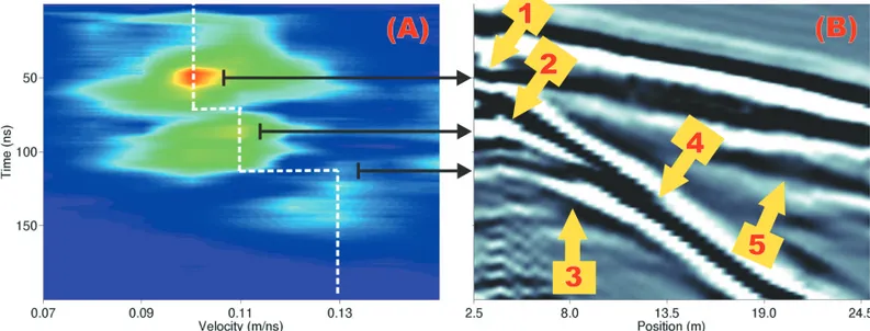
subsur-Figure 3 – (A) Semblance analysis and velocity model (in dash white line) for the CMP profile shown in (B). The black arrows link the highest values of coherency
in the velocity semblance panel (A) to the corresponding reflectors in (B). The critical angle is reached at short offsets for reflectors marked 1, 2 and 3 in (B): >2.5 m, 4.5 m and 8 m, respectively. Arrows indicate the maximum offset before reaching the critical angle, after that EM waves propagate as direct earth waves, marked 4 in (B). 5 is the EM propagation velocity in air.
face; the earlier the more numerous the diffractions are. In par-ticular they are not only more numerous before 270 ns but their tails are relatively shorter, indicating a relatively more conduc-tive horizon. The conspicuous clutter seen at those earlier times is due to the morainic till also seen in the active layer. There is a clear transition at 270 ns from a more conductive and inho-mogeneous horizon to a less conductive and a great deal less cluttered subsurface. This transition is beyond the reach of our velocity model, which last transition occurs within the cluttered horizon at TWT = 126 ns. This later time horizon is spatially inhomogeneous, having a more layered and relatively higher am-plitudes zone between 22 and 60 m, with good lateral continuity. Note that we do not have any independent information like stra-tigraphy, water content, or other borehole data to calibrate the GPR data so all information extracted from the GPR sections will be most qualitative.
We proceed analyzing the relative dielectric characteristics of the permafrost in a semi-quantitative way using a trial-and-error migration procedure on the fixed offset profile of Figure 2. The idea behind this is to take advantage of the clutter by trying distinct migration velocities until we are able to collapse the dif-fraction tails. Of course the migration velocity (vm) is at best an approximated estimate for the true medium velocity, v, proba-bly significantly poorer than the CMP estimates. But we can use vmto compare semi-quantitatively the electrical permittivities of distinct regions of the subsurface, beyond the reach of the sem-blance analysis. This is based in the fact that for GPR frequencies and conductivities less than 10 mS/m, the electromagnetic wave
propagation velocity can be approximated by (Davis & Annan, 1989) Eq. (1).
v= √c
k (1)
where v is medium velocity,c = 0.3 m/ns, the speed of light in a vacuum, andk is the dielectric constant.
Figure 4 – The migrated section with a single velocity of vm= 0.09 m/ns. The open ellipse shows smiles in a vertical I-shaped zone located between 22 and 60 m, indicating the need of adopting a smaller migration velocity.
We begin the procedure using the lower bound of the CMP derived velocity model of vC M P = 0.09 m/ns as shown in Fi-gure 2. The result of migrating the data with vm = 0.09 m/ns give rise to smiles at early times (TWT ≤ 270 ns) as well as at later times (400 ns ≥ TWT ≤ 700 ns; between 22 and 60 m), as seen in Figure 4, indicating the need of a lower velocity, or higher
“main” — 2009/4/1 — 19:07 — page 524 — #6
524
A GPR SURVEY ON DEGRADED PERMAFROST AT MES´ON SAN JUAN, MENDOZA, ARGENTINAFigure 5 – The final migrated section with velocities of vm= 0.09 m/ns (TWT ≤ 270 ns, d ≤ 22 m, d ≥ 60 m, TWT ≥ 270 ns) and vm= 0.03 m/ns (TWT > 270 ns, 22 m < d < 60 m, within the I-zone). A final gain was applied and color was added to the section to emphasize the lateral continuity achieved with the new migration procedure.
permittivity, which we interpret as a relative increase in water con-tent. The conspicuous smile at later times in the migrated section, Figure 4, is an indication of a smaller phase velocity inside a ver-tical I-shaped zone located between 22 and 60 m, surrounded by two zones of phase velocity vm = 0.09 m/ns. This I-zone cor-responds to the high amplitudes shown in the unmigrated section shown in Figure 2 what may indicate also that the conductivity is lower when laterally compared to the remainder of the section.
Proceeding further in the above procedure we have tried several values of vm ≤ 0.09 m/ns for migration of the I-zone. We found that the I-zone appears to be correctly migrated only with very low vm velocities. Figure 5 shows that the I-region is correctly migrated even with a phase velocity as low as vm = 0.03 m/ns, the velocity of EM waves in water. After migration the reflectors in the I-zone display lateral continuity to its sur-roundings. Therefore I-zone is characterized by low values for both phase velocity and conductivity. So it must be a region of high (free) water content and low ion contents, probably a zone with the highest porosity in the whole section, an indication of a degraded permafrost. Conversely the surrounding material of the I-zone will either have lower water content or, more probably, higher percentage of ice in relation to free water.
Earlier times than 270 ns show a chaotic characteristic due to its coarseness that will not improve much after migration. Notwithstanding that earlier time zone does need migration to col-lapse some of the diffraction tails seen in the unmigrated section. As in the I-region that early time region appears to be correctly migrated with a phase velocity of vm = 0.03 m/ns. Again the intense clutter as well as the unconsolidated characteristics of the surface favors a high porosity environment.
CONCLUSIONS
Our semi-quantitative velocity model allowed the construction of a three-zone permafrost subsurface. CMP data indicate the occur-rence of modal propagation of EM waves in a surficial waveguide probably formed by a low-velocity wet active layer over a higher velocity layer of frozen ground. Semblance analysis of the CMP data yielded a three-layer velocity compatible with a decreasing temperature/increasing density of a frozen ground.
The dielectric characteristics of the subsurface allowed the zoning of an I-zone of relatively low phase velocity. This I-zone is topped by a cluttered more conductive horizon reaching 270 ns, or 17 m, that encompass the active zone formed probably by mo-rainic till and cryogenic sediments. This earlier time horizon has
a lower velocity than the material surrounding the I-zone, indica-ting higher porosity and water contents, but due to its coarseness it is not easy to get an estimate for its velocity.
We do assume here that the differences in phase velocity are due to water (liquid or ice) contents. This zoning represents a conspicuous lateral change in water contents but is not as far-fetched as it may sound, as transitions from unfrozen to frozen conditions may be abrupt and without any surface expression (Arcone et al., 1998). The I-zone is probably a thawed satura-ted zone at least until TWT = 700 ns surrounded by frozen mate-rial. One possibility is that segment is a discharge channel linking a suprapermafrost, a laterally discontinuous near surface system not seen in the data to a subpermafrost aquifer (Lawson et al., 1996). Most probably the source of that water is the retreating glacier above the plateau that finds its way through the morainic till present in the active layer. As in other parts of the Central Andes glaciers retreat or disappear generating great quantities of melting water in summer, which penetrates into the periglacial soil or the cryolithozone and enhances permafrost degradation. These types of phenomena may be considered as indicators of global warming in the Andean peaks.
With the results of the correct migration velocities, all diffrac-tions are collapsed and the reflectors are placed in their true po-sitions. Based on the above discussion we can interpret our re-sults as shown in Figure 6. We expected to find the basement at 45-50 m but that is beyond the limit of our data. The use of GPR in the study area was shown quite effective in imaging the permafrost structures.
Figure 6 – An interpretation based on the semi-quantitative velocity model used
here superimposed on the final migrated section of Figure 5. C has a compara-tively low conductivity, high porosity and moisture (liquid water) by weight and low ion contents. It is not possible to infer a lower limit for this zone. A and B have higher percentage of ice in relation to liquid water.
ACKNOWLEDGMENTS
We are indebted to our Argentinean colleagues from Instituto Ar-gentino de Nivolog´ıa, Glaciolog´ıa y Ciencias Ambientales – Con-sejo Nacional de Investigaciones Cient´ıficas y T´ecnicas (IANIGLA-CONICET), Jos´e Hern´andez and Jos´e Corval´an for their technical support, Alberto Aristarain (LEGAN) and to the Argentinean Army that gave invaluable logistical support to the work. JMT acknowl-edges a grant from the Conselho Nacional de Desenvolvimento Cient´ıfico e Tecnol´ogico (CNPq).
REFERENCES
ANNAN AP, WALLER WM, STRANGWAY DW, ROSSITER JR, REDMAN JD & WATTS RD. 1975. The electromagnetic response of a low-loss, 2-layer, dielectric earth for horizontal electric dipole excitation. Geophysics, 40: 285–298.
ANNAN AP & DAVIS JL. 1976. Impulse radar sounding in permafrost. Radio Science, 11(4): 383–394.
ARCONE SA, LAWSON DE & DELANEY AJ. 1995. Short-pulse radar wavelet recovery and resolution of dielectric contrasts within englacial and basal ice of Matanuska Glacier, Alaska, U.S.A. Journal of Glaciology, 41(137): 68–86.
ARCONE SA, DELANEY AJ & WILLIAMS C. 1996. Geological and Geo-physical Investigations of the Hydrogeology of Fort Wainwright, Alaska: Part I. Canol Road Area. CRREL Report, 96-4: 1.
ARCONE SA, LAWSON DE, DELANEY AJ, STRASSER JC & STRASSER JD. 1998. Ground-penetrating radar reflection profiling of groundwater and bedrock in an area of discontinuous permafrost. Geophysics, 63(5): 1573–1584.
ARCONE SA, PEAPPLES PR & LIU L. 2003. Propagation of a ground penetrating radar (GPR) pulse in a thin-surface waveguide. Geophysics, 68(6): 1922–1933.
ARCONE SA, FINNEGAN DC & LIU L. 2006. Target interaction with stra-tigraphy beneath shallow, frozen lakes: Quarter-wave resonances within GPR profiles. Geophysics, 71(6): K119–K131.
BERGERON V, BERGER C & BETTERTON MD. 2006. Controlled Irradia-tive Formation of Penitents. Physical Review Letters, 96, 098502. BROSTEN TR, BRADFORD JH, McNAMARA JP, ZARNETSKE JP, GOOSEFF MN & BOWDEN WB. 2006. Profiles of temporal thaw depths beneath two arctic stream types using ground-penetrating radar. Perma-frost and Periglacial Processes, 17(4): 341–355.
BROWN J, FERRIANS Jr. OJ, HEGINBOTTOM JA & MELNIKOV ES. 1998. Circum-Arctic Map of Permafrost and Ground-Ice Conditions. National Snow and Ice Data Center/World Data Center for Glaciology. Digital Media.
“main” — 2009/4/1 — 19:07 — page 526 — #8
526
A GPR SURVEY ON DEGRADED PERMAFROST AT MES´ON SAN JUAN, MENDOZA, ARGENTINA CHEN R, KANG E, JI X, YANG J & YANG Y. 2006. Cold Regions in China.Cold Regions Science Technology, 45: 95–102.
DAVIS JL & ANNAN AP. 1989. Ground-penetrating radar for high reso-lution mapping of soil and rock stratigraphy. Geophysical Prospecting, 37: 531–551.
GARLEFF K & STINGL H. 1986. Geomorphologische Aspekte aktuellen und vorzeitlichen Permafrostes in Argentinien. Zentralblatt fuer Geolo-gie und PalaeontoloGeolo-gie, Teil I: Allgemeine, Angewandte, Regionale und Historische Geologie, 9/10: 1367–1374.
GRUBER S & LUDWIG F. 1996. Application of Ground Penetrating Radar in Glaciology and Permafrost Prospecting Arctic Studies. Programme at the Arctic Centre, Rovaniemi, Finland, 5–6.
LAWSON DE, STRASSER JC, STRASSER JD, ARCONE SA, DELANEY AJ & WILLIAMS C. 1996. Geological and Geophysical Investigations of the Hydrogeology of Fort Wainwright, Alaska: Part I. Canol Road Area. CR-REL Report, 96-4: 32.
LEUSCHEN C, KANAGARATNAM P, YOSHIKAWA K, ARCONE SA & GOGINENI P. 2003. Design and field experiments of a ground-penetrating radar for Mars exploration. Journal of Geophysical Research-Planets, 108(E4): GDS 15–1.
NRC. 2006. What is Permafrost?. Natural Resources Canada, Geological Survey of Canada. Available at:
<http://www.gsc.nrcan.gc.ca/permafrost/whatis e.php>. Access on: Feb. 25th, 2006.
TRAVASSOS JM & SIM˜OES JC. 2004. High-resolution radar mapping of internal layers of a subpolar ice cap, King George Island, Antarctica. Pesquisa Ant´artica Brasileira. Brazilian Academy of Sciences, 4: 57–65. TROMBOTTO D. 2000. Survey of Cryogenic Processes, Periglacial Forms and Permafrost Conditions in South America. Revista do Insti-tuto Geol´ogico, S˜ao Paulo, 21(1/2): 33–55.
TROMBOTTO D. 2002. Inventory of fossil cryogenic forms and structures in Patagonia and the mountains of Argentina beyond the Andes. South African Journal of Science, 98: 171–180.
TROMBOTTO D & BORZOTTA E. 2009. Indicators of present global war-ming through changes in active layer-thickness, estimation of thermal diffusivity and geomorphological observations in the Morenas Coloradas rockglacier, Central Andes of Mendoza, Argentina. Cold Regions Science and Technology, 55: 321–330.
TROMBOTTO D, BUK E & HERN´ANDEZ J. 1997. Monitoring of Mountain Permafrost in the Central Andes, Argentina. Permafrost and Periglacial Processes, 8: 123–129.
UNEP. 2007. Global outlook for ice and snow. United Nations En-vironment Programme, Nairobi, Birkeland Trykkeri, Birkeland, Norway, 235 pp.
VAN EVERDINGEN R. 1998. Multi-Language Glossary of Permafrost and Related Ground-Ice Terms. International Permafrost Association, Arctic Institute of North America, University of Calgary, Canada, 47 pp.
NOTES ABOUT THE AUTHORS
Jandyr de Menezes Travassos is a senior researcher at the National Observatory of Rio de Janeiro, since 1977. Bachelor in Physics at the Federal University of
Rio de Janeiro (UFRJ), Master degree in Geology at UFRJ, Doctoral degree at the University of Edinburgh (UK), Posdoctoral at the Lamont-Doherty Observatory (USA). He works in Applied Geophysics, using electromagnetic methods.
Giovanni Chaves Stael is a technologist at the National Observatory of Rio de Janeiro, since 2002. Bachelor in Mechanical Engineering at Santa ´Ursula University
(USU), Master degree at the Technological Institute of Aeronautics (ITA) and Doctoral degree at the State University of Norte Fluminense (UENF). He works in the Applied Geophysics area, using electromagnetic methods and Petrophysics.
Dario Trombotto Liaudat is a Geologist. He obtained his B.Sc. degree at the Universidad Nacional de C´ordoba (Argentina), and his doctoral degree at the
Geographis-ches Institut Heidelberg, Ruprecht Karls Universit¨at Heidelberg (Germany). At present, he coordinates research projects in the field of Geocryology at the Regional Center of Technological and Scientific Investigation (CCT – Conicet) in his native country.