Universidade do Minho
Escola de Engenharia
Philippe Daniel Pinto Ferreira
Development of a two-dimensional
biomechanical multibody model for the
analysis of the human gait with an
ankle-foot orthosis
12
Philippe Daniel Pint
o F err eir a De velopment of a tw
o-dimensional biomechanical multibody model
for t
he anal
ysis of t
he human gait wit
h an ankle-foo
t or
M.Sc. Dissertation
Integrated Master in Biomedical Engineering
Biomaterials, Biomechanics and Rehabilitation
Universidade do Minho
Escola de Engenharia
Philippe Daniel Pinto Ferreira
Development of a two-dimensional
biomechanical multibody model for the
analysis of the human gait with an
ankle-foot orthosis
Dissertation done under the supervision of
João Paulo Flores Fernandes
DECLARAÇÃO
Nome: Philippe Daniel Pinto Ferreira
Título dissertação: Development of a two- dimensional biomechanical multibody model for the analysis of the human gait with an ankle-foot orthosis
Orientador: João Paulo Flores Fernandes Ano de conclusão: 2012 Designação do Mestrado: Mestrado Integrado em Engenharia Biomédica
É AUTORIZADA A REPRODUÇÃO INTEGRAL DESTA TESE/TRABALHO APENAS PARA EFEITOS DE INVESTIGAÇÃO, MEDIANTE DECLARAÇÃO ESCRITA DO INTERESSADO, QUE A TAL SE COMPROMETE;
Universidade do Minho, ___/___/______
The total number of persons with paralysis, deformity or orthopedic
impairments that use orthoses is expected to reach
7.3 million by the year 2020.
ACKNOWLEDGMENTS
This dissertation wouldn’t have been possible without the help and support of the kind people around me.
First and foremost, I would like to thank my family who encourages and stimulates me during the whole year.
I am sincerely and heartily grateful to my supervisor, Professor Paulo Flores, for believing in my potential and accepting to supervise my project. His insights and periodic advices were essential to complete this work.
I am deeply grateful to the whole team of the Department for Mechanics and Robotics from the Duisburg-Essen University. I was very well welcomed and learnt a lot during my semester there. I would like to thank in particular to Professor Andrés Kecskeméthy who was kind to receive me in his research group. He was patient enough to clarify all my doubts and his motivation, interest and support help me to overcome all the obstacles.
I would also like to thank Professor Mario Siebler from the Heinrich-Hein University, in Düsseldorf for receiving me in his clinic, giving me the clinical perspective to the ankle foot orthoses, providing me two pairs of orthoses and for his availability to find patients for data acquisition in the gait lab.
This project was developed under the project DACHOR and I would like to thank the MIT Portugal Program for this opportunity to work in this interesting topic and for the fellowship I was awarded.
Finally, I would like to thanks all my friends, in Portugal, Germany and elsewhere, who gave me constant moral support and boost my productivity.
TITLE
Development of a two-dimensional biomechanical multibody model for the analysis of the human gait with an ankle-foot orthosis
KEYWORDS
Biomechanics Ankle-foot orthosis Gait analysis
Human body simulation Forward dynamics
ABSTRACT
Ankle-foot orthoses are orthotic devices that support the ankle joint and are appropriate for several pathologies, mostly the ones that cause dropfoot, which is caused by an ankle joint deficiency.
In the present work, a planar multibody model of the human body in the sagittal plane was developed. For this purpose, the MOBILE computational program was utilized. The model simulates the lower limbs and is made of 9 rigid bodies. It has 12 DOFs and is prepared for reproducing kinematic data acquired in a gait lab.
Kinematic measurements were obtained in a gait lab from a healthy subject, with and without plastic ankle foot orthoses worn on both feet. The results obtained showed that with the orthoses, the ankle joint behavior is similar to a linear torsional spring, with almost no hysteresis.
Ankle kinematics, measured in the gait lab with and without orthoses, were successfully reproduced by forward dynamics using the multibody model developed, which allows for the validation of the presented approach.
Furthermore, it was concluded that ankle foot orthoses can be modeled as a spring element acting at the ankle joint, and the use of an ankle foot orthosis reduces the muscle activation at the ankle in about 15%.
TITEL
Entwicklung eines Zwei-Dimensional Biomechanische MB Modell für die Analyse der menschlichen Gang mit einem Knöchel-Fuß Orthese
STICHWORTE
Biomechanik
Knöchel-Fuss Orthesen Ganganalyse
Menschliche Körper Simulation Vorwärts Dynamik
ABSTRAKT
Knöchel-Fuß-Orthesen sind orthopädische Geräte, die das Sprunggelenk zu unterstützen und sind für verschiedene Erkrankungen, vor allem diejenigen, die dropfoot, die von einer Sprunggelenks-Mangel verursacht wird dazu führen, angemessen.
In der vorliegenden Arbeit wurde ein planarer Multibody Modell des menschlichen Körpers in der Sagittalebene entwickelt. Zu diesem Zweck wurde das MOBILE Rechenprogramm verwendet. Das Modell simuliert die unteren Extremitäten und wird von 9 starren Körpern. Es verfügt über 12 Freiheitsgrade und ist für die Wiedergabe kinematische Daten in einer Ganglabors erworbenen vorbereitet.
Kinematische Messungen wurden in einem Ganglabors von einer gesunden Person erhalten, mit und ohne Kunststoff Sprunggelenk Orthesen an beiden Füßen getragen. Die erhaltenen Ergebnisse zeigten, dass mit den Orthesen, das Sprunggelenk Verhalten ähnlich einer linearen Torsionsfeder ist, fast ohne Hysterese.
Knöchel Kinematik, in der Ganglabors mit und ohne Orthesen gemessen wurden erfolgreich von Vorwärtsdynamikanalyse Verwendung der Multibody Modell entwickelt, das für die Validierung der dargebotenen Ansatz ermöglicht reproduziert.
Darüber hinaus wurde festgestellt, dass Sprunggelenk Orthesen als Feder wirkende Element am Sprunggelenk modelliert werden können, und die Verwendung eines Fußheberorthese verringert die Muskelaktivität am Knöchel in etwa 15%.
TÍTULO
Desenvolvimento de um modelo biomecânico multibody bidimensional para a análise da marcha humana com uma ortótese do tornozelo
PALAVRAS CHAVE
Biomecânica
Ortótese do tornozelo Análise da marcha humana Simulação do corpo humano Dinâmica direta
RESUMO
As ortóteses do tornozelo são dispositivos ortopédicos que apoiam a articulação do tornozelo e são indicados para uma variedade de patologias, nomeadamente as que causam pé pendente, que é uma deficiência na mobilidade do tornozelo.
No presente trabalho, um modelo multibody planar do corpo humano no plano sagital foi criado. Para tal, o software MOBILE foi usado. O modelo simula os membros inferiores e é composto por nove corpos rígidos. Possui 12 graus de liberdade e está preparado para usar dados cinemáticos adquiridos num laboratório de análise da marcha humana como restrições de guiamento.
Dados cinemáticos foram obtidos num laboratório de análise da marcha humana, a partir de um indivíduo saudável, com e sem ortóteses plásticas em ambos os pés. Os resultados mostraram que, com a ortótese, o comportamento da articulação do tornozelo é semelhante a uma mola de torção linear, praticamente sem histerese.
Os dados cinemáticos do tornozelo, medidos no laboratório de marcha, com e sem ortótese, foram reproduzidos com sucesso por uma dinâmica direta, utilizando o modelo multibody desenvolvido, o que validou a abordagem utilizada.
Todas as metodologias encontram-se descritas e explicadas nesta tese e concluiu-se que a ortóteconcluiu-ses do tornozelo podem concluiu-ser modeladas como uma mola de torsão que actua na articulação do tornozelo. Concluiu-se também que a utilização de uma ortótese do tornozelo por uma pessoa saudável reduz a activação muscular do mesmo em cerca de 15%.
TABLE OF CONTENTS
ABSTRACT ... vii
ABSTRAKT ... ix
RESUMO ... xi
TABLE OF CONTENTS ... xiii
ABBREVIATIONS AND ACRONYMS ... xv
LIST OF FIGURES ... xvii
LIST OF TABLES ... xxi
CHAPTER 1 – INTRODUCTION ... 1
1.1 Motivation ... 3
1.2 Objectives and thesis organization... 4
1.3 Literature review ... 5
1.4 Contributions of the thesis ... 10
CHAPTER 2 – ANKLE AND FOOT ANATOMY, BIOMECHANICS AND ANKLE-FOOT ORTHOSES ... 11
2.1 Ankle and foot anatomy ... 13
2.2 Ankle and foot motion ... 16
2.3 Human gait description ... 21
2.4 Lower limb orthoses ... 24
2.5 Ankle-foot orthosis (AFO) ... 24
2.6 Requirement for AFOs ... 27
2.7 Biomechanics of AFOs ... 29
CHAPTER 3 – MODELLING THE HUMAN BODY ... 33
3.1 MOBILE description ... 35
3.2 Development of the full-body model ... 36
3.2.1 Parameters of the model ... 37
3.2.2 Foot geometry ... 38
3.3 Foot model ... 39
3.3.1. Literature review on contact foot models ... 39
3.3.2. Development of the foot model ... 40
CHAPTER 4 – METHODS, RESULTS AND DISCUSSION ... 45
4.1 Data acquisition in the gait lab... 47
4.1.1 Results with and without orthosis ... 48
4.1.2 Issues with the implementation ... 50
4.2 Reader procedure ... 55
4.3 Ankle angle over time plots ... 55
4.4 Forward dynamics ... 57
4.4.1. Barefoot results ... 58
4.4.2. Orthosis results ... 61
CHAPTER 5 – CONCLUSIONS AND FUTURE WORK ... 65
5.1 Ankle foot orthoses ... 67
5.2 MOBILE and methodologies ... 67
5.3 Advantages of the methodologies ... 68
5.4 Limitations ... 68
5.5 Future work ... 68
REFERENCES ... 71
APPENDIX I – N’PENDULUM CODE FOR MOBILE ... 77
APPENDIX II – READER.CPP ... 83
APPENDIX III – ANTHROPOMETRIC SCRIPT FOR MATLAB ... 97
APPENDIX IV – FOOT GEOMETRY CODE ... 103
APPENDIX V – ANGLE CALCULATION IN MATLAB ... 107
APPENDIX V.A – READC3D SCRIPT ... 109
APPENDIX V.B – INTEGRATOR SCRIPT ... 114
APPENDIX V.C – FINAL MATRIX SCHEME ... 116
ABBREVIATIONS AND ACRONYMS
2D Two-dimensional 3D Three-dimensional 3PP Three point pressure AAFO Active ankle-foot orthosis AFO Ankle-foot orthosis CM Center of mass DOF Degree-of-freedom FEM Finite element model GRF Ground reaction force HAT Head, arms and trunk HKAFO Hip-knee-ankle-foot orthosis HS Heel strike
IR Infra-red
KAFO Knee-ankle-foot orthosis LFEO Left Femur Origin
LHEE Left Heel
LHJC Left Hip Joint Center LHUP Left Posterior Humerus LTIO Left Tibia Origin
LTOE Left Toe
MBS Multibody system MSE Mean squared error
oHS Opposite heel strike
oTO Opposite toe off PELO Pelvis Origin
PLS Posterior leaf spring PPT Pain pressure threshold PP Polypropylene
RFEO Right Femur Origin RHEE Right Heel
RHJC Right Hip Joint Center RHUP Right Posterior Humerus RTIO Right Tibia Origin
RTOE Right Toe
RTOETIP Right Toe Tip
SIMM Software for Interactive Musculoskeletal Modeling THKAFO Trunk-hip-knee-ankle-foot orthosis
LIST OF FIGURES
Chapter 1
Figure 1.1 3D FEM of the ankle-foot orthosis system (Chu et al., 1995) ... 6 Figure 1.2 (a) Five-segment diagram of human’s body and (b) schematic of
gait cycle for quantifying the function of AFO (Jamshidi et al.,
2008) .. 7
Figure 1.3 (a) Biomechanical model of the human body constituted by 12 rigid segments interconnected by geometrical ideal revolute joints, (b) multibody model of the AFOs and (c) schematic locations of sphere/plane contact points between the AFO and the lower limb (Silva et al., 2010) ... 8 Figure 1.4 Representation of the two-dimentional, 7-segments model with
representation of the AFO as a passive spring (Bregman et al., 2011) ... 9
Chapter 2
Figure 2.1 Ankle ligaments. (a) Lateral/outer and (b) Medial/inner ligaments (De Burgh, 2003) ... 14 Figure 2.2 Bones of the foot (Tortora and Derrickson, 2008) ... 15 Figure 2.3 Lateral view of arches of the right foot (Tortora and Derrickson,
2008) ... 15 Figure 2.4 Retinacula of the ankle (Tortora and Derrickson, 2008) ... 16 Figure 2.5 Muscles of the leg that move the foot and toes (Tortora and
Derrickson, 2008) ... 17 Figure 2.6 Intrinsic muscles of the leg that move the toes (Tortora and
Derrickson, 2008) ... 18 Figure 2.7 Anatomical position, with three reference planes and six
fundamental directions (Tortora and Derrickson, 2008) ... 19 Figure 2.8 Ankle movements. (a) Dorsiflexion and (b) plantarflexion ... 19 Figure 2.9 Movements of the foot. (a) Toe motion, (b) hindfoot motion, (c)
and (d) forefoot motion plantarflexion (Tortora and Derrickson, 2008) ... 20 Figure 2.10 Movements of the ankle-foot complex. (a) Supination and (b)
Figure 2.11 Typical normal gait cycle by the right leg (black) illustrating the major events and phases of gait, adapted from Winter (2009)... 22 Figure 2.12 Timing of single and double support phases during both legs gait
cycles (Whittle, 2007) ... 22 Figure 2.13 Lower limb orthoses. (a) AFO (Advanced Orthotic Designs Inc.),
(b) KAFO (Advanced Orthotic Designs Inc.), (c) HKAFO (Advanced Orthotic Designs Inc.) and (d) THKAFO (ProWalk, 2009) ... 24 Figure 2.14 Ankle foot orthosis Knit-Rite SmartKnit® AFO Liner (Knit-Rite,
2010) ... 25 Figure 2.15 Ankle foot orthoses. (a) Metal AFO (OrthoMedics, 2011), (b)
plastic AFO (OrthoMedics, 2011), (c) hinged plastic AFO (OrthoMedics, 2011) and (d) carbon fiber AFO (Kinetic Research, 2011) ... 26 Figure 2.16 Variants of plastic AFO orthoses. (a) Spiral AFO (Edelstein and
Bruckner, 2002), (b) hemispiral AFO (Lower Extremity Review Magazine, 2011), (c) ground reaction AFO (NovitaTech, 2010), (d) bi valved AFO (NovitaTech, 2010), (e) circumferential AFO (NovitaTech, 2010) and (f) supramalleolar AFO (NovitaTech, 2010) ... 28 Figure 2.17 Graphical representation of the (a) three and (b) four point
pressure systems (Pakistan Academy of Orthotists & Prosthetists, 2009) ... 30 Figure 2.18 Three point pressure systems of an AFO developed to prevent (a)
plantarflexion and (b) dorsiflexion (Pakistan Academy of Orthotists & Prosthetists, 2009)... 30 Figure 2.19 GRF control in the sagittal plane at heel strike (a) without AFO
and (b) with AFO (Pakistan Academy of Orthotists & Prosthetists, 2009) ... 31
Chapter 3
Figure 3.1 (a) Simple pendulum, (b) Double pendulum and (c) Triple pendulum ... 35 Figure 3.2 N’pendulum creator, (a) Example of parameters inserted by the
user and (b) Initial conditions for the parameters set in (a) ... 36 Figure 3.3 MBS model created in MOBILE for gait analysis ... 37
Figure 3.4 Foot geometry used in the simulation ... 39
Figure 3.5 Milliard foot contact models (Millard et al., 2008) ... 39
Figure 3.6 Moreira’s foot contact model (Moreira et al., 2009) ... 40
Figure 3.7 Two cylinder-plane foot contact model (Kecskeméthy, 2001) ... 40
Figure 3.8 Foot geometry with identification of the spheres position used in the contact model ... 41
Figure 3.9 Foot with the pre-defined markers and the additional-one at the toe tip ... 41
Figure 3.10 Graphical representation of the friction cone ... 43
Chapter 4
Figure 4.1 (a) Position of the markers and (b) subject with the markers on his skin ... 48Figure 4.2 Fixation of the orthosis to the subject foot and shank with adhesive tape ... 49
Figure 4.3 Moment/angle plots obtained in the gait lab (a) in a barefoot acquisition (red continuous line) and (b) with orthoses on both feet (blue dotted line) ... 50
Figure 4.4 Position of the PELO point and the markers placed at the hip, adapted from Paolini (2010)... 51
Figure 4.5 Projection of the coordinates in the yOz plane by removing the x-coordinate ... 51
Figure 4.6 Identification of the points and markers used for the right lower limbs angles computation ... 52
Figure 4.7 Hip angle (α) ... 53
Figure 4.8 Knee angle (φ) ... 53
Figure 4.9 Ankle angle (δ)... 53
Figure 4.10 Metatarsal angle (ψ) ... 54
Figure 4.11 Graph obtained in the gait lab presenting the evolution of the ankle angle during the gait cycle. Heel strike (HS), toe off (TO), opposite TO (oTO), heel rise (HR) and opposite HS (oHS) were identified for a stride, as well as the stance and swing phase ... 56
Figure 4.12 Graphical representation of some of the stance phase events: (a) heel strike, (b) foot flat and (c) pre-swing period, adapted from Voglewede (2007) ... 57
Figure 4.13 Representation of the ankle angle in three distinct configurations: (a) foot sole perpendicular to the shank, (b) foot in a plantarflexion position and (c) foot in a dorsiflexion position ... 57 Figure 4.14 Graph presenting the evolution of the ankle moment during the
measured gait ... 59 Figure 4.15 Ankle kinematics. (a) Measured (blue dotted line) and (b)
obtained by forward dynamics (red line). These results were obtained for the barefoot trial with the best fit ... 61 Figure 4.16 Ankle-foot orthosis meshing in Ansys® ... 62 Figure 4.17 Moment applied at the ankle for the (a) barefoot simulation (blue
dotted line) and (b) the simulation with AFO with α = 85% (red continuous line) ... 63 Figure 4.18 Ankle kinematics. (a) Measured (blue dotted line) and (b)
obtained by forward dynamics (red line). These results were obtained for the orthosis trial with the best fit ... 64
LIST OF TABLES
Chapter 1
Table 1.1 Description of the materials in the contact points (Silva et al., 2010) ... 8
Chapter 2
Table 2.1 Sub phases of the gait cycle with particular emphasis on the ankle joint (Whittle, 2007) ... 23 Table 2.2 Pathologies associated with the use of AFOs (Advanced Orthotic
Designs Inc., Silva et al., 2010, OrthoMedics, 2011, Chu, 2001) ... 29 Table 2.3 Effects of lever arm and surface area in AFOs, adapted from
Pakistan Academy of Orthotists & Prosthetists (2009) ... 31
Chapter 3
Table 3.1 Anthropometric parameters of the MBS model (Winter, 2009) ... 38
Chapter 4
Table 4.1 Comparison of the type of joints in the reader and integrator models ... 58 Table 4.2 Contact and friction properties that better reproduce the ankle
joint kinematics ... 60 Table 4.3 Metatarsal spring-damper parameters ... 60 Table 4.4 AFO spring-damper parameters ... 63
CHAPTER 1
– INTRODUCTION1.1 Motivation
Biomechanics is the scientific domain which deals with the study of biological systems, such as the human body, using physical concepts and mechanical engineering methodologies (Whittle, 2007). Biomechanics is a large area and it is possible to find biomechanics engineers studying many different aspects of biological systems, such as rehabilitation, ergonomics, biomaterials and biotribology, biofluid, among others.
The human gait, in particular, is easily identified as a mechanical process and since it is performed by a biological system, it is appropriate to study it as a mechanical system. In turn, mechanical engineering is a vast subject that involves Newtonian mechanics and materials sciences but the most relevant concepts for the gait analysis are time, mass, force, center of gravity, torques, and motion, both linear and angular (Whittle, 2007).
Since biological systems are commonly more complex than man-built mechanical systems, the biomechanical approach employed to for their study can be extremely mathematical and numerical methods are often applied. However the basic principles are easy to understand.
Biomechanics research is done in an iterative process of hypothesis and verification that normally include modeling, computer simulation and experimental validation of the results.
The present work focuses a well-known medical device, the ankle-foot orthosis (AFO). The necessity for orthotic devices is increasing and, since this kind of device plays an important role in restoring the normal gait to patients suffering from ankle disabilities, it is a relevant study subject.
Lower limb orthoses were the most common orthotic device used, covering 55% of the orthoses provided in the United States of America (USA) in 2007. AFOs in particular represent almost half of this category with 26% and proved to be the most common type of orthoses (American Board for Certification in Orthotics Prosthetics and Pedorthics Inc., 2007). Nowadays, the elderly population is increasing and this growth in the number of elderly people will have an impact in the number of AFOs needed. This fact will have economic implications and AFOs proved to be an increasing market, since their base cost was between $500 and $700, according to a Medicare review payment data for the years 2001 to 2006 (American Orthotic and Prosthetic Association Inc., 2008).
1.2 Objectives and thesis organization
The main goal of this work is to develop a biomechanical multibody (MBS) model for human gait analysis that includes the AFO properties. The model must be able to simulate the orthosis effect on a patient using an AFO. Another purpose of this work deals with the effect of AFOs on the energy consumption associated to the human gait.
The specific objectives of this investigation can be listed as follows:
To build up a planar model of the lower limbs in the sagittal plane using the subject-oriented biomechanics library MOBILE;
To acquire kinematic data on a gait lab (with and without orthosis); To use the kinematic data as an input to drive the MBS model; To reproduce the results using forward dynamics;
To include the AFOs properties in the model;
To compare the energy consumption with and without AFOs.
The model here proposed is a planar model that uses the subject-oriented biomechanics library MOBILE. During the gait cycle, the major forces and the major amplitude of movements are expected in the sagittal plane (Silva et al., 2010). For this reason and for simplicity purposes, the developed model is a 2D approach in the sagittal plane. Since the AFO is a passive device, it does not have an actuator and the model cannot have a power supply.
This dissertation is organized as follows:
In Chapter 1, an overview of the dissertation is provided, objectives are defined and a literature review is made to characterize the existing MBS models of the human body that includes AFOs.
In Chapter 2, the anatomical and biomechanical perspective of the ankle-foot complex is presented. Motion allowed by the ankle joint is defined and the phases of the gait cycle are described. All kinds of lower limb orthoses are covered with particular attention to AFOs. Pathologies leading to the AFO necessity are listed and the biomechanical effect of these orthotic devices is explained.
Chapter 3 describes the MBS model developed in this work. The software used, MOBILE, is presented and the first models developed in this programming environment are referred. The MBS model is described, with particular emphasis on the foot and on
the contact foot model. A short literature review on contact foot models is also done to contextualize the developed model.
Chapter 4 covers the methodologies employed. First, the data acquisition in the gait lab is referred and explained. Then, the problems faced and their corresponding solutions are presented. Ankle moment over ankle angle and ankle angle over time plots are studied, since they represent the incoming results. The model was tested with barefoot kinematical data which were reproduced successfully by forward dynamics. The same methodologies were applied in order to reproduce the kinematical data measured in the gait lab with an orthosis, but the ankle moment was reduced and the AFO was replaced by a spring-damper element applied at the ankle joint.
Finally, Chapter 5 summarizes the main conclusions of the present work, as well as the advantages and limitations of the methodologies employed. Some suggestions for future developments are also presented.
1.3 Literature review
Much research has been made attending to understand all the process of walking, and nowadays, it is a well-studied area (Abboud, 2002, Whittle, 2007). The human walking is a process that involves many organs, such as the brain, spinal cord, peripheral nerves, muscles, bones and joints, and to understand it correctly it is crucial to know the basics about anatomy, physiology and biomechanics (Whittle, 2007).
Some work has been done on modeling the normal and the pathological gait, regarding to the muscle activation (Lamontagne et al., 2002) and trying to understand pain (Callaghan and Baltzopoulos, 1994). Many research work have been published on the characterization of the mechanical properties of AFOs (Yamamoto et al., 1993, Bregman et al., 2009, Crabtree and Higginson, 2009, Lai et al., 2010) or the effect of this type of orthosis on the pathological gait (Romkes and Brunner, 2002, Gordon et al., 2006, Brehm et al., 2008). However, there are not many available literature on the modeling of the human gait with an AFO.
The first attempt to model an AFO with the ankle-foot complex was published by Chu et al. (1995). Before this date, only few papers related to the behavior of AFOs under static forces can be found (Leone et al., 1988, Leone et al., 1991). These authors compare results from beam theory, finite elements and experimental results in order to predict the AFO deflection.
In 1995, a 3D finite element model (FEM) of an AFO together with the entire ankle-foot complex was developed using ADINA software (see Fig. 1.1)(Chu et al., 1995). A static analysis was performed for two of the most relevant instants in gait cycle, namely the heel strike and the toe off. The authors showed that significant stress concentrations occur in the heel and the neck regions of the AFO. The peak tensile stress (0.8 MPa) and compressive stress (1.6 MPa) occurred in the neck region of the orthosis during toe off and in the heel region during the heel strike, respectively. Since then, Chu’s group has published other relevant works about stress analysis of polypropylene AFOs (Chu and Reddy, 1995, Chu and Feng, 1998, Chu, 2000, Chu, 2001).
Most recently, in 2008, a new model for the gait simulation combining the AFO function and steppage gait was developed by Jamshidi et al. (2008). In this study, a five-segment MBS model of the human body in the sagittal plane was created, as it is illustrated in Fig. 1.2a. This AFO considers the role of a spring-damper system between the foot and the shank (see Fig. 1.2b) that compensate muscle weakness. The dynamic model was solved by inverse dynamic, in which the value of the spring constant (k) varies from 1 to 75 N.m.rad-1, and the damper constant (c) is null. Comparing the value of the calculated torque in ankle joints with the value for normal gait found in the literature, it was concluded that the ideal values were and .
Later on, the same group (Jamshidi et al., 2009) applied their previous model, using inverse dynamics, with kinematics data from a Guillan-Barré patient with
dropfoot disorder. The aim of the study was to estimate how the spring coefficient affects the torque generated at the ankle to optimize the human gait.
Crabtree and Higginson (2009) developed an AFO model as an adjustable torque applied at the ankle joint. This torque varies in function of joint angle and velocity and its behavior was obtained experimentally with a dynamometer. In this paper, the authors apply this model on the right leg of a 9 degrees-of-freedom (DOF), 11 segment model of the musculoskeletal system developed in SIMM (Software for Interactive Musculoskeletal Modeling, Musculographics, Inc.) with 15 muscles per leg. The right ankle presented passive stiffness and the model was solved in forward dynamics. Some changes in neuromuscular control of ankle plantarflexors and dorsiflexors were observed in response to the moments provided by the AFOs.
Silva et al. (2010) developed a new MBS model of an active AFO that can be integrated in a whole-body MBS human model with 12 DOFs, as it is shown in Fig. 1.3a. This model (see Fig. 1.3b) was developed in the MATLAB environment and it was created to evaluate the contact forces generate in the lower limb/AFO interface. The aim of this study was to evaluate the comfort of the patient, checking if the contact forces were below the pain pressure thresholds (PPTs). The contact model used is a contact model between a deformable sphere and a rigid plane (see Fig. 1.3c). According to this investigation, there are nine contact points between the orthosis and the lower limb, as it is presented in Tab. 1.1. Kinematic data as well as ground reaction forces (GRFs) of a healthy subject were acquired in a gait lab. Two simulations were performed, in forwards dynamics, using the biomechanical model (see Fig. 1.3a) and driving the joints with the kinematic data acquired. The first simulation used all the
(a) (b)
Figure 1.2 (a) Five-segment diagram of human’s body and (b) schematic of gait cycle for quantifying
kinematic data while in the second one, the ankle joint was considered to be free in order to simulate the dropfoot as a total absence of muscular action. The second simulation included the AFO model (see Fig. 1.3b) in both legs. The AFOs prescribed the kinematic data of the ankle joint. The weight of each rigid segment and the weight of the AFOs were applied to the center of mass of each segment and on the ankle joint of the AFOs, respectively. Finally, the GRFs were applied under the foot in the first simulation and under the orthoses plantar modules in the second one. The results presented a very close gait pattern. The moments at the ankle joint, knee and hip were calculated and compared, revealing very close values. The pressures at the contact points were also evaluated and it was concluded they were below the PPTs.
Table 1.1 Description of the materials in the contact points (Silva et al., 2010) Contact Point Deformable Sphere Rigid Plane
1 Straps Bone prominences
2 Straps Bone prominences
3 Straps Bone prominences
4 Soft tissues Structural nondeforming orthosis 5 Soft tissues Structural nondeforming orthosis 6 Soft tissues Structural nondeforming orthosis 7 Soft tissues Structural nondeforming orthosis 8 Soft tissues Structural nondeforming orthosis
9 Straps Bone prominences
Most recently, Bregman et al. (2011) developed a forward-dynamic conceptual walking 2D model with a passive spring at the ankle representing the AFO. This model
(a) (b) (c)
Figure 1.3 (a) Biomechanical model of the human body constituted by 12 rigid segments
interconnected by geometrical ideal revolute joints, (b) multibody model of the AFOs and (c) schematic locations of sphere/plane contact points between the AFO and the lower limb (Silva et al.,
(see Fig. 1.4) consists of 7 rigid segments powered by two constant torques applied at the hip. Those torques are consistent with compensation strategies in patients with impaired push-off. All the joints were frictionless. The knee joints were locked in full extension by jambs during stance phase and modeled as hinge joints with hyperextension stop during swing phase. During swing and stance phase, a flexion torque and an extension torque were applied on the upper leg, respectively. The interactions between the model and the floor were modeled as unilateral constraints located at the heel and toes. These constraints were activated based on kinematic events, that is when the heel or the toes touched the floor and deactivated when the vertical forces between the contact points of the foot and the floor decreased to zero. The ankle was modeled as a free hinged joint, showing a completely paralyzed ankle, and the only moment acting at this articulation was the linear rotational spring. Simulations were performed in MATLAB by solving the equations of motion in a forward dynamic fashion for a broad range of AFO stiffnesses. Walking speed and step length were kept constant by adapting the magnitude of the hip flexion and extension torques. The results were computed for seven different velocities. The energy cost of walking was calculated as the sum of the amount of positive work done by the two constant hip torques. Finally, it was concluded that the patient energy cost of walking is directly dependent on the AFO stiffness and the proper choice of orthosis reduces the energy consumption of walking.
Figure 1.4 Representation of the 2D, 7-segments model
with representation of the AFO as a passive spring (Bregman et al., 2011)
1.4 Contributions of the thesis
The first three chapters of the thesis consist of a literature review and important background knowledge is collected. A literature review on the modeling of the human gait with an AFO is presented. The ankle-foot complex anatomy, gait cycle and lower limb orthoses are characterized with particular emphasis on AFOs and their necessity. A few solutions, existing in the literature, on modeling the human body are discussed. The model is described and all stages of its development are listed and reported.
Kinematic measurements are made in a gait lab and it was noticed that when wearing AFOs on both feet, the ankle moment varies linearly with the ankle angle, which proves that the AFO can be modeled as a linear torsional spring applied at the ankle.
The developed model has been tested and proved to be appropriate to reproduce the ankle kinematics during stance phase by forward dynamics. The author has written the whole code which is presented in appendices.
CHAPTER 2
– ANKLE AND FOOT ANATOMY, BIOMECHANICS AND ANKLE-FOOT ORTHOSESANKLE AND FOOT ANATOMY, MOTION AND ANKLE-FOOT
ORTHOSES
On this chapter, ankle and foot anatomy are described in order to provide basic knowledge of the limbs physiognomy under study. The ankle and foot motion is discussed and a gait cycle analysis is made. Lower limbs orthosis are referred with particular emphasis on the AFOs. Finally, pathologies that may require AFOs are listed and the biomechanics of AFOs are explained.
2.1 Ankle and foot anatomy
The ankle and the foot are a complex mechanical structure consisting of bones, ligaments, tendons and muscles. Ligaments have the function of connecting the bones to each other, reinforcing and stabilizing articulations. Tendons are bands of fibrous tissue connecting the muscles to the bones. Their function is to transfer the force developed by the muscle to the bones, creating movement. The ankle-foot complex plays a primordial role in the human locomotion since it supports the total body weight during the gait cycle.
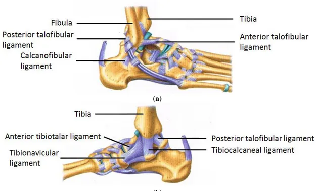
At the ankle joint, the lower ends of the tibia and fibula form a deep socket which will fits the upper surface of the talus, or ankle bone. The articular surface of the joint is covered with a smooth hyaline cartilage surrounded a synovial membrane filled of synovial fluid. The shape of the bones and the strength of the surrounding ligaments maintain the ankle stable, while still allowing the necessary freedom of movement. A tough fibrous capsule surrounds the joint and is reinforced on each side by the medial (inner) and lateral (outer) ankle ligaments, as Fig. 2.1 shows (Grabner, 2003).
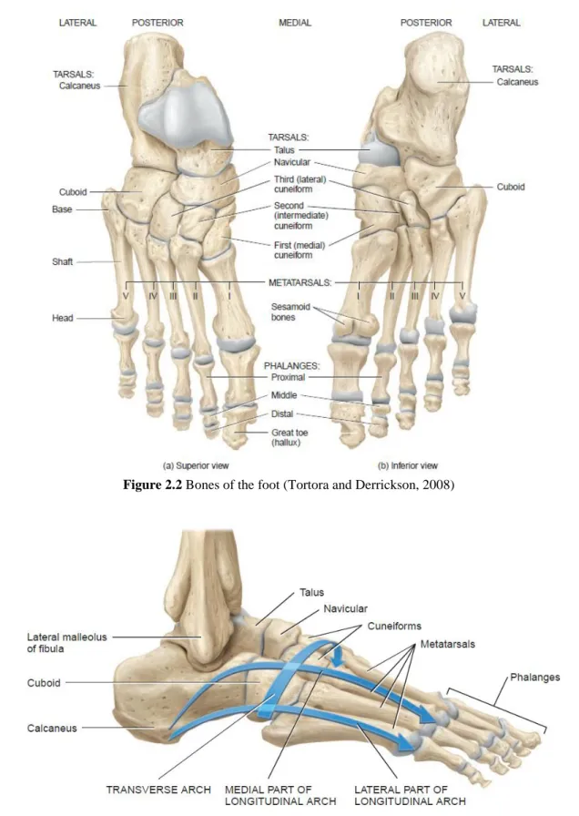
The human foot is made of 26 bones: 7 tarsal bones, 5 metatarsals and 14 phalanges (see Fig. 2.2). The talus articulates with the tibia and the fibula and bears the full weight of the body. It remains above the calcaneus, which is the largest bone foot. It is a large and strong bone whose function is to transmit the body weight from the talus to the ground. The calcaneus has bearing surfaces where it forms joints with the talus above and the cuboid in front. The cuboid has approximately the shape of a cube. The navicular is a relatively small bone located at the talus front and above the cuboid. The three remaining tarsal bones are the cuneiforms, named according to their positions: medial, intermediate and lateral. The medial cuneiform is the largest of these wedge-shaped bones (De Burgh, 2003).
The metatarsals and phalanges are miniature long bones since they consist of a base, a shaft and a head and their function is to provide stability to the foot. The bases
of the metatarsal articulate with the tarsal bones in the midfoot and the heads articulate with each toes’ phalanges. There are 14 phalanges in the foot, which are smaller and less mobile than those of the fingers, but their arrangement is the same. Each toe has three phalanges, except for the big toe (or hallux) which has only two (see Fig. 2.2) (De Burgh, 2003).
The bones of the foot are arranged in two bridgelike arches that are held in position by ligaments and tendons (see Fig. 2.3).
The foot arches allow the foot to support the total body weight, providing an ideal distribution over soft and hard tissue the foot and leverage while walking. Normally, the forefoot carries about 40% of the weight and the heel carries the remaining 60% (Tortora and Derrickson, 2008).
The two arches are supported by several ligaments that lie on the plantar surface of the foot and provide a strong but flexible base. The three major ligament are the plantar calcaneonavicular ligament, the long plantar ligament and the plantar calcaneocuboid ligament (De Burgh, 2003, Tortora and Derrickson, 2008).
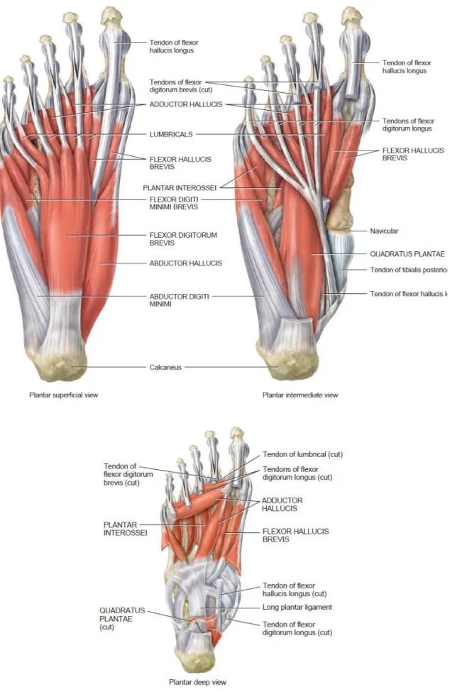
Muscles are soft tissues that contract and exert forces on tendons, which in turn pull one bone (or skin). Most muscles are attached to the articulating bones and are responsible for the articulation movement (Tortora and Derrickson, 2008). There are several muscles responsible for the foot and toes movement. They are located on the leg
(a)
(b)
and foot and many of them cross the ankle articulation. A series of fibrous bands, retinacula, held them firmly in place (De Burgh, 2003). Fig. 2.4 shows the superior and inferior extensor retinaculum whose function is to retain the extensor muscles.
Figure 2.3 Lateral view of arches of the right foot (Tortora and Derrickson, 2008) Figure 2.2 Bones of the foot (Tortora and Derrickson, 2008)
Muscles that move the foot and toes can be found on the leg (see Fig. 2.5) and intrinsic muscles of the foot are responsible for the movement of the toes (see Fig. 2.6) (Tortora and Derrickson, 2008).
However, despite the muscles are presented and identified in Figs. 2.5 and 2.6, they will not be described because such details are out of the scope of this thesis.
2.2 Ankle and foot motion
The ankle-foot complex is a multiarticular mechanical structure consisting of bones, joints and soft tissues. It plays an important role since it is the end part of the lower kinetic chain where external forces are applied (GRFs). The foot is the only part of the body that acts on an external surface, the ground, providing support during standing and stabilizing the body during gait (Abboud, 2002).
The foot has six joints: the ankle, subtalar, midtarsal, tarsometatarsal, metatarsophalangeal and interphalangeal, which are controlled by extrinsic and intrinsic muscles (see Figs. 2.5 and 2.6).
In order to describe the motion of the limbs and joints, three reference planes (see Fig. 2.7) are usually used, namely:
1. A sagittal plane is any plane which divides part of the body into right and left portions. The median plane is the midline sagittal plane, which divides the whole body into right and left halves;
2. The frontal plane, also called coronal plane, divides a body part into anterior and posterior portions;
3. The tranverse plane, or horizontal plane, divides body parts into upper and lower portions (Tortora and Derrickson, 2008).
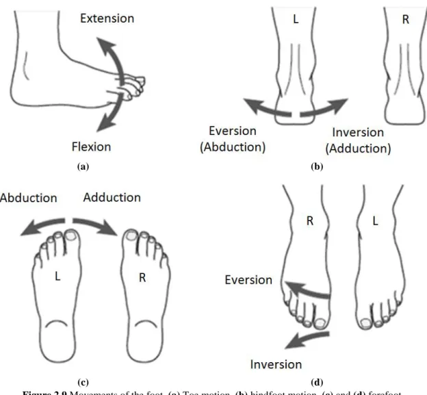
The planes referred in Fig. 2.7 are useful to define the joints movements. Most joints only enable movement in one or two of the planes. The possible movements are listed below and illustrated in Figs. 2.8, 2.9 and 2.10, for the case of the ankle-foot complex.
1. Flexion and extension occur in the sagittal plane. At the ankle joint, these movements are called dorsiflexion and plantarflexion, respectively (see Fig. 2.8);
2. Abduction and adduction take place in the frontal plane;
3. Internal and external rotation, also called medial and lateral rotation, take place in the transverse plane (Tortora and Derrickson, 2008).
(a) (b)
Figure 2.8 Ankle movements. (a) Dorsiflexion and (b) plantarflexion Figure 2.7 Anatomical position, with three reference planes and six
The ankle joint is a major weight bearing hinge joint connecting the foot to the leg and mostly responsible for dorsiflexion (toes up, heel down) (see Fig. 2.8a) and plantarflexion (toes down, heel up) (see Fig. 2.8b). However, it also allows a slight movement in the transverse plane during plantarflexion, resulting in instability while in this position. The ankle joint is essential to the normal locomotion and the minimum range of motion necessary for a normal gait cycle is from 10º of dorsiflexion to 20º of plantarflexion (Flores et al., 2006, Tortora and Derrickson, 2008, Moreira, 2009).
The ankle-foot complex can also perform combined movements, in order to provide both flexibility and stability during gait, such as supination and pronation (see Fig. 2.10) which are allowed by the subtalar joint. As supination (see Fig. 2.10a) can be seen as the equivalent to a simultaneous inversion, plantarflexion and adduction, pronation (see Fig. 2.10b) is comparable to simultaneous eversion, dorsiflextion and abduction (Abboud, 2002, Tortora and Derrickson, 2008).
(a) (b)
(c) (d)
Figure 2.9 Movements of the foot. (a) Toe motion, (b) hindfoot motion, (c) and (d) forefoot
2.3 Human gait description
Normal human walking can be defined as a process of locomotion involving the use of the two legs, alternately, to provide support and propulsion, with at least one foot in contact with the ground at all instants (Hunt and Crossley, 1975, Whittle, 2007). The terms walking and gait are often used interchangeably but they differs slightly since the term walking refers to the locomotion process itself and the term gait refers to the “the manner or style of walking”. Thus, it makes more sense to compare gait patterns than walking (Whittle, 2007).
The normal gait is a concept hard to describe since it comprises both feminine and masculine genders and a wide range of extremities of body geometry. Therefore, the normal gait is the one that is within the normal limits considered appropriate for each sex and age (Rose and Gamble, 2005, Whittle, 2007).
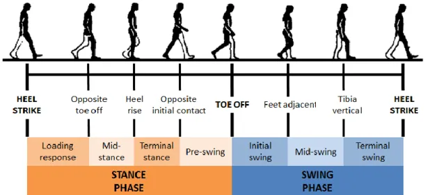
The human walking is a periodical movement and the gait cycle is defined as the time interval which separates two successive occurrences of one of the repetitive events of walking. It is conventionally accepted that the gait cycle starts, and ends, with the initial contact of the right foot. During the gait cycle, seven major events can be identified, namely:
1. Initial contact or heel strike (HS) 2. Opposite toe off
3. Heel rise
4. Opposite initial contact
5. Terminal contact or toe off (TO) 6. Feet adjacent
7. Tibia vertical
(1. Next cycle initial contact)
(a) (b)
Figure 2.10 Movements of the ankle-foot complex. (a) Supination and (b) pronation
These seven events are illustrated in the sequence of Fig. 2.11. Thus, the gait cycle is divided in seven periods, which are described in Tab. 2.1 and are grouped in two distinct phases: stance and swing phases (see Fig. 2.11). The stance phase, also called support phase or contact phase lasts from heel strike to toe off, while the swing phase lasts from toe off to heel strike.
In each gait cycle, there are also two period of double support, i.e., periods of time when both feet are in contact with the ground, as it can be observed in Fig. 2.12. The stance phase usually lasts about 60% of the cycle, the swing phase about 40% and each period of double support about 10% (Whittle, 2007).
It must be noticed that the terms heel strike and toe off can only be applied to the non-pathological gait. Initial and terminal contact are often used in the bibliography,
Figure 2.12 Timing of single and double support phases during both legs gait cycles (Whittle, 2007) Figure 2.11 Typical normal gait cycle by the right leg (black) illustrating the major events and phases
since in pathological gait the heel and the toes may not be the first and last part of the foot to touch and leave the ground, respectively.
Table 2.1 Sub phases of the gait cycle with particular emphasis on the ankle joint (Whittle, 2007)
Stance
ph
ase
1. Loading response Loading response is the double support period between heel strike and opposite toe off. During this period, the foot is lowered to the ground by plantarflexion and the GRF increases rapidly in magnitude, as total plantar contact is reached.
Usually, it lasts the first 10-12% of the cycle.
2. Mid-stance Mid-stance is the period between opposite toe off and heel rise.
During this phase, the shank is rotating forward about the ankle joint, as the foot sole remains in full contact with the ground. Thus, the ankle angle changes from plantarflexion to dorsiflexion.
It represents about 18% of the gait cycle.
3. Terminal stance Terminal stance starts at heel rise (or heel off) and ends when the opposite heel strike occurs. At the end of terminal stance, the dorsiflexion reaches its maximum value.
It represents 20% of the gait cycle.
4. Pre-swing. Pre-swing starts at the opposite heel strike and ends when the stance limb toe off occurs. It is the second double support period of the gait cycle. During this period, the ankle movement changes into plantarflexion and the peak of ankle plantarflexion occurs at toe off. Pre-swing lasts about 10% of the gait cycle.
Sw
ing p
hase
5. Initial swing Initial swing begins at toe off and continues until the maximum knee flexion occurs, which coincide with feet adjacent position, i.e., when the swing foot overtake the stance foot.
During the swing phase, the ankle is moving from a plantarflexed position at toe off towards a neutral or dorsiflexed attitude in terminal swing.
It lasts about 15% of the gait cycle.
6. Mid-swing Mid-swing is the period between feet adjacent and tibia vertical. At this phase, the ankle attitude becomes less important and it may be anywhere between a few degrees of plantarflexion and a few degrees of dorsiflexion.
Mid-swing represents 10% of the gait cycle.
7. Terminal swing. Terminal swing is the final phase of the swing phase. It is the deceleration phase where the knee fully extends in preparation for heel strike. In this phase, the ankle muscles activity increases to hold the ankle in position in anticipation of the greater contraction forces developed during the loading response.
2.4 Lower limb orthoses
Orthoses are medical devices that support or correct the function of a limb or the torso (Edelstein and Bruckner, 2002). They are also known as braces or caliper. In particular, a lower limb orthosis is an external device that is applied or attached to a lower limb. Its function is to control motion, provide support, reduce pain, correct flexible deformities or prevent the progression of fixed deformities (Alexander et al., 2011).
Orthoses are usually named according to their location in the body. There are four major types of lower limb orthosis (Edelstein and Bruckner, 2002), namely:
Ankle-foot orthosis – AFO (see Fig. 2.13a);
Knee-ankle-foot orthosis – KAFO (see Fig. 2.13b); Hip-knee-ankle-foot orthosis – HKAFO (see Fig. 2.13c);
Trunk-hip-knee-ankle-foot orthosis – THKAFO (see Fig. 2.13d) (Edelstein and Bruckner, 2002)
In the context of the present work, AFOs are considered only.
2.5 Ankle-foot orthosis (AFO)
An AFO is usually an orthosis that covers portion of the foot and the leg (Harris et al., 2008). It features a flat shoe sole for the foot, spans the ankle joint and covers the
(a) (b) (c) (d)
Figure 2.13 Lower limb orthoses. (a) AFO (Advanced Orthotic Designs Inc., 2011), (b) KAFO
(Advanced Orthotic Designs Inc., 2011), (c) HKAFO (Advanced Orthotic Designs Inc., 2011) and (d) THKAFO (ProWalk GmbH, 2009)
lower leg (Edelstein and Bruckner, 2002, Vasconselos, 2010) (see Fig. 2.14). An essential element of AFOs is an anterior strap located just below the knee which secures the leg against the posterior calf shell (Edelstein and Bruckner, 2002).
AFOs are passive medical devices, i.e., they do not have any kind of energy supply. The term AFO should not be confused with AAFO that refers to an active ankle-foot orthosis. The AAFO consists of a generic AFO endowed of an electromechanical device that controls the ankle movements (Silva et al., 2010), thus it can force the patient ankle to assume the normal kinematic of the human gait.
AFOs can be found in pre-manufactured versions but for specific pathologies a proper custom-made solution is required. This is why the orthotic devices have evolved based on accumulate experience. Nowadays, researchers and engineers are trying to apply medical knowledge, material science and biomechanical principles to create orthoses that respond to the specific needs of every patient.
For long, AFO properties, such as rigidity and buckling, had caused problems (Golay et al., 1989). More recently, some studies using a 3D FEM of the AFO and the foot were performed in order to study the AFO behavior and to determine the maximum tensile stress and its location during gait cycle (Chu et al., 1995). Other authors developed an alternative method to evaluate the properties of the orthoses, such as the fatigue strength (Lai et al., 2010) or the stiffness and neutral angle around the ankle and metatarsal-phalangeal joints (Bregman et al., 2009).
In a clinical perspective, much work has been done on the evaluation of the effect of the orthosis support on gait analysis of patients. The patterns of motion of the pelvis, hip and knee of children affected by different degrees of lumbosacral
Figure 2.14 Ankle foot orthosis Knit-Rite SmartKnit®
myelomeningocele with and without orthoses had been illustrated and compared (Vankoski et al., 1995). The frequency of adjustments and replacement of the orthosis has also been evaluated (Supan and Hovorka, 1995). There are some works on how the use of an AFO changes the kinematic and the kinetic of human gait (Huang et al., 2006, Silva et al., 2011). The influence of the AFO in the patterns of muscular activity has been investigated in order to understand the neuromuscular adaptation associated with the use of the orthotic device (Crabtree and Higginson, 2009). The contact forces (Silva et al., 2010) and the pain pressure threshold (Coutinho et al., 2011) in the orthosis/lower limb interface have also started to be explored to ensure the patient comfort.
AFOs can be classified according to the material they are made of, as Fig. 2.15 shows.
Metal AFOs consist of a shoe or foot attachment, an ankle joint, two metal uprights (medial and lateral) with a calf band connected proximally (see Fig. 2.15a). They are indicated for several specific pathologies, including the insensate foot, the foot with fluctuating edema, or when the need for adjustability or progressive changes in the device are indicated (Cooper, 2006, Alexander et al., 2011).
There are two types of ankle joints used in metal AFOs:
Single-channel ankle joints, which provide dorsiflextion assistant and a plantarflexion stop;
Dual-channel ankle joints, which assist the foot both in the dorsiflexion and plantarflexion directions (Cooper, 2006).
Plastic AFOs (see Fig. 2.15b) are the most common type of AFO. They are mostly made from a thermoplastic material, polypropylene (PP), for the structural
(a) (b) (c) (d)
Figure 2.15 Ankle foot orthoses. (a) Metal AFO (OrthoMedics, 2011), (b) plastic AFO (OrthoMedics,
2011), (c) hinged plastic AFO (OrthoMedics, 2011) and (d) carbon fiber AFO (Kinetic Research Inc., 2011)
components and Velcro straps for tightening (Silva et al., 2010). They can be fabricated from a cast or molding of the patient’s limb. The first approach may be suitable for short-term use but the second-one is better for durable use (Cooper, 2006), allowing choosing the plastic type, color and thickness. The general features of a plastic AFOs would include the trimlines (degree of rigidity), degrees of dorsiflexion, and foot plate design (Cooper, 2006).
The main characteristic of plastic AFOs is the posterior leaf spring (PLS) design. This the most common form of AFO with a narrow calf shell and a narrow ankle trim line behind the malleoli. It is typically set in 5-7º of dorsiflexion with very low-profile three-quarters length footplate. The PLS is used for compensating flaccid footdrop by resisting ankle plantarflexion at heel strike and during swing phase (Edelstein and Bruckner, 2002, Cooper, 2006, OrthoMedics, 2011).
Plastic AFOs can also incorporate a hinged joint at the ankle (see Fig. 2.15c) which will allow some dorsiflexion and a limited plantarflexion. However, hinged-AFOs are less adjustable than metal AFO joints. The footplate design can incorporate three-quarter length, which stops just before the metatarsal heads for easier access into shoes, or a full length footplate with padding, which is generally used for the most spastic or most vulnerable foot (Cooper, 2006).
There are also many variants of plastic AFOs, designed for specific diseases (see Fig. 2.16) (Edelstein and Bruckner, 2002, Alexander et al., 2011). However, in this work, it is not relevant to describe them because of their specificity.
Carbon AFOs (see Fig. 2.15d) have been widely used during the last decade. Carbon fiber is a material extremely lightweight, and durable, however it is not adjustable and does not fit perfectly in the limb. This style of AFO is best used for isolated foot drop (OrthoMedics, 2011).
2.6 Requirement for AFOs
AFOs are prescribed and used to restore normal motion or to constrain and inhibit abnormal motion (Chu, 2001). They can be used to improve the base of support of patients with balance perturbation but they also improve ankle kinematics during stance phase, increase step and stride length, decrease cadence, and decrease energy costs in walking, while improving walking, running and jumping skills (Chen et al., 1999, Brehm et al., 2008, Harris et al., 2008).
AFOs are indicated for a great variety of pathologies which may be neurological, vascular or orthopedic (see Tab. 2.2). Many patients suffering from these pathologies have lack of control of the lower limbs, necessity of lowering the pressure on the feet or need for support (Silva et al., 2010). A very common symptom in these cases is the dropfoot.
Dropfoot is an abnormal neuromuscular disorder characterized by a steppage gait that affects the patient’s ability to raise their foot at the ankle, and is further characterized by an excessive and uncontrolled plantarflexion, an inability to point the toes towards the body (dorsiflexion) or move the foot at the ankle inwards or outwards. The dropfoot motion will lead to toe dragging during the swing phase of the gait cycle and result in pain and weakness. Moreover, numbness may accompany loss of function (Chu, 2001, Jamshidi et al., 2009).
AFOs can also be used to provide support in cases of general weakness and positional support for patients with Excessive Muscle Tone, Paralysis, or Congenital Deformity. Finally, they can be applied to immobilize the foot/ankle in cases of Charcot Feet, Fracture, Arthritis, or Wound Management (OrthoMedics, 2011). However, the most common application of AFOs is to provide support for dropfoot or for ankle instability associated with several conditions some of which include stroke, spina bifida,
(a) (b) (c)
(d) (e) (f)
Figure 2.16 Variants of plastic AFO orthoses. (a) Spiral AFO (Edelstein and Bruckner, 2002), (b)
hemispiral AFO (Lower Extremity Review Magazine, 2011), (c) ground reaction AFO (NovitaTech, 2010), (d) bi-valved AFO (NovitaTech, 2010), (e) circumferential AFO (NovitaTech, 2010) and (f)
cerebral palsy, Lou Gehrig's Disease, multiple sclerosis, paraplegia or poliomyelitis (Advanced Orthotic Designs Inc., 2011).
Table 2.2 Pathologies associated with the use of AFOs (Chu, 2001, Silva et al., 2010, Advanced Orthotic
Designs Inc., 2011, OrthoMedics, 2011)
List of Pathologies Cerebral palsy Stroke
Lou Gehrig's disease Multiple sclerosis Poliomyelitis Paraplegia
Paralysis (Hemiplegia) Nerve Damage
Spinal cord injuries Excessive muscle tone Traumatic brain injuries Neuropathy
Charcot Feet
Congenital deformities Injuries/Fractures
Joint diseases (e.g. Arthritis) Muscular dystrophy
Spina bifida General weakness Wound management
2.7 Biomechanics of AFOs
In order to maintain the anatomical joints in their proper positions and to restrain abnormal movement, orthosis design is normally based on two types of forces system: the three point pressure (3PP control) and the GRF control (Edelstein and Bruckner, 2002, Pakistan Academy of Orthotists & Prosthetists, 2009).
In the first case (3PP), it is intended to block or restrain the rotation of two body segments about the anatomical joint that unites them. An example is given in Fig. 2.17a on how the rotation of an articulation can be prevented by applying three forces: one at the free end of each segment (F1 and F2) and a third force directly at the revolute joint (F3). A variation of the 3PP control system, often used in orthotic practice, is the four point pressure system (see Fig. 2.17b). In this system, the force F3 is replaced by two forces (F4 and F5) to decrease the pressure applied directly at the anatomical joint.
In the case of AFOs, the 3PP control system is applied to prevent motion the anatomical joints of the ankle foot complex. Figure 2.18 shows the forces developed by an AFO on the ankle joint to restrain plantarflexion (see Fig. 2.18a) and dorsiflexion (see Fig. 2.18b).
The GRF control aims to rectify the motion of a body segment and/or a joint using (or not) an orthopedic device during the stance phase, i.e., when the foot contacts the floor.
At heel strike, the heel hits the floor and a GRF is generated as an equal and opposite force. If the total body weight is not aligned with the ankle joint, the GRF will create a plantarflexion moment at the ankle joint (see Fig. 2.19a). However, as many patients have a foot disability, dropfoot, they cannot dorsiflex their foot back to a neutral position. For this reason, the AFO is used to restrain the plantarflexion at the initial contact in the gait cycle, and the GRF is transferred to the next free joint in the kinematical chain – the knee joint (see Fig. 2.19b), creating a flexion moment and preventing knee hyperextension (Pakistan Academy of Orthotists & Prosthetists, 2009).
In AFOs design, changing the lever arm length or the surface area can increase the patient’s comfort. Since the moment M developed at the ankle joint can be calculated
(a) (b)
Figure 2.18 Three point pressure systems of an AFO developed to prevent (a)
plantarflexion and (b) dorsiflexion (Pakistan Academy of Orthotists & Prosthetists, 2009)
(a) (b)
Figure 2.17 Graphical representation of the (a) three and (b) four point
through the equation , increasing the length l will reduce the force F developed between the orthosis and the patient limb. The pressure exerted on the patient skin is also a matter of concern and may reach relatively high values. However it can be easily decreased by an increase of the surface area as the pressure is inversely proportional to the surface area, (Pakistan Academy of Orthotists & Prosthetists, 2009).
Table 2.3 shows the different combinations of lever arm length and calf shell surface area. The optimum solution to assure both efficiency and patient comfort is to maximize the length of the lever arm and the calf surface area.
Table 2.3 Effects of lever arm and surface area in AFOs,
adapted from Pakistan Academy of Orthotists & Prosthetists (2009)
Lever arm length
short increased Su rf ac e ar ea Small increased (a) (b)
Figure 2.19 GRF control in the sagittal plane at heel strike (a) without AFO
CHAPTER 3
– MODELLING THE HUMAN BODYThe following chapter begins by presenting the software used, MOBILE, and the first simple models developed to get familiar with this programming environment. The MBS model is described, with particular emphasis on the contact foot model. Relevant contact foot models existing in the literature are referred and described in order to contextualize the developed model.
3.1 MOBILE description
MOBILE code is an object-oriented programming package designed for the modeling of MBS (Kecskeméthy, 1999). It is a software developed by Professor Andrés Kecskeméthy and is still being developed and improved at the Duisburg-Essen University. It allows for an intuitive 3D representation of mechanical elements that can transmit motion and forces, being the modeling of mechanical systems as executable programs. The implementation is portable and efficient since it is based on the object-oriented programming language C++, and the building-block system design is open, allowing the user to extend the provided library in any direction. To facilitate the visualization of the simulation, it is also possible to import geometries from .so (UNIX®, The Open Group) or .iv (Open InventorTM, Silicon Graphics Incorporated) files (Kecskeméthy, 1999).
The first work completed on MOBILE was the modeling and simulation of simple models, namely pendulums (see Fig. 3.1). The first model created was the simple pendulum described in the User’s Guide (see Fig. 3.1a). This model revealed to be useful to consolidate the concepts learnt during the lecture of the MOBILE User’s Guide (Kecskeméthy, 1999). With the modeling of these concepts, the basic MOBILE objects and the structure of the program becomes clear and the user become more familiar and confident with the programming in C++.
(a) (b) (c)
After the simple pendulum analysis (see Fig. 3.1a), a double (see Fig. 3.1b) and a triple pendulum (see Fig. 3.1c) were modeled, only with the addition of rigid bodies, joints and masses to the kinematical chain.
Finally, an N’pendulum was created. In this model, all the parameters of the model are inserted by the user (number of bars, lengths, masses and initial conditions), as it is represented in Fig. 3.2. The code for the N’pendulum is attached on Appendix I.
3.2 Development of the full-body model
A biomechanical model of the human body was constructed in MOBILE. This model is bi-dimensional and was constructed in the sagittal plane, since the major amplitude of movement and forces occur on this plane during the gait cycle (Silva et al., 2010).
The MBS model illustrated in Fig. 3.3 consists of a pair of legs that represent the human lower limbs, totalizing 9 rigid bodies, 10 revolute joints and 2 prismatic joints. Each leg was built up by 4 rigid bodies (thigh, shank, foot and toes) and an additional body was created to represent the upper-body. This last body is called HAT and has the total mass of the upper-body (Winter, 2009). All the bodies are linked by revolute joints. Three additional DOFs were added at the hip (translations in two directions and rotation in the sagittal plane, in this order), so the model can move freely in the plane.
The first simulation procedure with this model consisted of driving all the joints with time functions. In this way, the whole system is rheonomic since all the DOFs were guided. The time functions were obtained in a gait lab. This model, called “Reader”, is nothing more than a player that allows the user to visualize the measurements in MOBILE. The code for the “reader.cpp” is included in Appendix II.
(a) (b)
Figure 3.2 N’pendulum creator. (a) Example of parameters inserted by the user and (b) Initial conditions for the