Deposition of TiO
2Film on Duplex Stainless Steel Substrate Using the Cathodic Cage
Plasma Technique
Rômulo Ribeiro Magalhães de Sousaa*, Francisco Odolberto de Araújob, José Alzamir Pereira da
Costac, Akio Nishimotod, Bartolomeu Cruz Vianae, Clodomiro Alves Jr.b
Received: June 17, 2015; Revised: June 15, 2016; Accepted: August 20, 2016
This research used the “cathodic cage (CC)” technique for TiO2 ilm deposition on duplex stainless
steel substrate. This technique uses a multiple hollow cathode efect. Duplex stainless steel substrates were treated at temperatures of 300oC, 350oC and 400oC, giving a temperature value ratio (T
s/Tm) of
0.27 to 0.31 (Ts being the substrate temperature and Tm the melting temperature of the deposited material). Treatment times of 1, 2 and 4 hours were administered and polycrystalline TiO2 ilms were
obtained. The ilms were analyzed by optical microscopy (OM), X-ray difraction (XRD), Raman spectroscopy and scanning electron microscopy (SEM). During analysis, the formation of uniform ilms and the possibility of controlling the TiO2 phase were observed. It was also shown that with
longer treatment times and higher temperatures the rutile phase predominates. For treatment times of 4 hours at all temperatures, the rutile structure was present. With treatment times of less than 4 hours, anatase was present. In addition, results showed that this simple, low cost technique can be an alternative method for depositions of TiO2 ilms, with the advantage of high levels of control over
porosity, thickness and phase composition (anatase and rutile).
Keywords: Cathodic Cage; titanium dioxide; duplex stainless steel; TiO2 thin ilms
* e-mail: [email protected]
1. Introduction
TiO2 is a transition metal oxide which has been studied
extensively, mainly because of its excellent dielectric, optical and electronic properties. TiO2 has wide range applications,
including environmental puriication, self-cleaning surfaces, and photo induced hydrophilicity1-5, in addition to being an
important biocompatible material1,4. TiO
2 crystallizes in
anatase, rutile or brookite structural phases. The properties
of TiO2 ilms are known to be related to the amount to which
the phases are present in the deposited layer3. Many studies
have focused on the dependence of the obtained phase on preparation methods, deposition parameters, substrate type, doping of metallic and nonmetallic species3,6. Anatase TiO
2 is
considered one of the best photocatalysts with high activity and non-toxic properties5, furthermore, it exhibits high chemical
reactivity and stability under UV illumination2, which leads
to greater possibilities for practical application as antibacterial
agents2-5, self-cleaning surfaces7, organic photo degradation8,6,
and hydrogen generation by the splitting of water, termed solar-hydrogen6,9,10. In addition, depending of phase and preparation conditions, anatase TiO2 has high durability,
high refractive index (n = 2.3), high resistivity and dielectric
constant11 k, with values from 30 to 100, so it is suitable for
applications in optical wave-guides12, antirelection coatings13,
photochemical solar cells14,15 and gas sensors11,12. Photons with
energy equal or higher than the energy band gap (~3.2eV) are able to generate electron/hole pairs7 and have energy
high enough to initiate redox and oxidation reactions16. For
example, excited electrons can reduce oxygen to superoxide radicals, whilst the holes oxidize water molecules into hydroxyl radicals5,13. These intermediate species induce the
decomposition of various molecules such as those which are organic or microbes, which leads to the self-cleaning ability and anti-microbial applications of a TiO2 surface
17. In order
to improve and expand upon the range of applications some modiications have been studied and several approaches have been proposed: First, to reduce the band gap of TiO2 with
the intention of improving the light absorption in the visible region, studies have been conducted involving doping with metallic and non-metallic impurities4-6,18.
Second, to elucidate the inluence of synthesis techniques, as well as ilm deposition methods and substrate type, many chemical and physical processes and techniques have been carried out and great advances have emerged2,9,14,17.
aDepartamento de Mecânica, Instituto Federal do Piauí – IFPI, Teresina, PI, Brazil
bDepartamento de Ciência Exatas e Naturais, Universidade Federal Rural do Semi-Árido – UFERSA,
Mossoró, RN, Brazil
cDepartamento de Física, Universidade do Estado do Rio Grande do Norte – UERN, Mossoró, RN,
Brazil
dFaculty of Chemistry, Materials and Bioengineering, Kansai University, Osaka, Japan
Recent investigations have included the use of practical and economical substrates such as metallic materials5,15,16,20.
The particular properties of metals, such as its conductivity, lexibility, mechanical robustness and capacity to be shaped easily can change the photocatalytic characteristics and expand the possibility for practical application7,16, such as
self-cleaning surfaces, antibacterial agents, photo degradation of organics, use in the manufacture of components introduced in hospital equipment, utensils for food preparation and air
conditioning11,14.
Several methods have been used successfully to
deposit TiO2 thin films, including the sol–gel21 method
by hydrolysis of Ti(OiPr)4, followed by calcination
at 500–600oC, chemical vapor deposition2,4,10 (CVD),
physical vapor deposition (PVD), chemical bath deposition (CBD), reactive sputtering and atomic layer deposition (ALD)8,14,19,22,23. Low-pressure chemical vapor deposition
(LPCVD) routes have been used to grow TiO2 on a diverse
range of substrates14. It has been shown8,25 that, with a
deposition temperature greater than 400oC, TiO
2 films
are polycrystalline, whilst temperatures lower than 400oC
lead to an amorphous structure and that the structural phase grown depends on the physical and chemical characteristics of the substrate. It was found that films grown on glass substrates present a rutile tetragonal structure, while on ITO-coated glass substrates films grow in an anatase structure8,25.
According to Movchan and Demchishin26, the
microstructure of metal and oxide thin films is related to the homologous temperature, i. e. Ts/Tm (Ts is the temperature
of the substrate and Tm is the melting temperature of the deposited material). The structural morphologies have three well-defined structural zones26,27,28: The first zone - T
s/Tm
<0.3 - is characterized by small, elongated grains, with a columnar structure and a porous morphology, where there is a weak binding between the grains. The columnar structure is produced by low diffusion of surface adsorbed atoms through the substrate and atomic shadow effects that are dependent on the speed of growth of the columns and on the various incidence angles when the atoms reach the substrate surface. In the present work, TiO2 thin films
were produced using the so-called cathodic cage24,29
(CC) method. The CC method is a hybrid technique, which promotes both the deposition and diffusion of chemical elements on the surface. The method used is such that the homologous temperature falls in the range 0.27≤Ts/Tm ≤0.31, where the microstructure of the film
is characterized according to descriptions of ‘first zone’ described earlier by Movchan et al.
2. Experimental
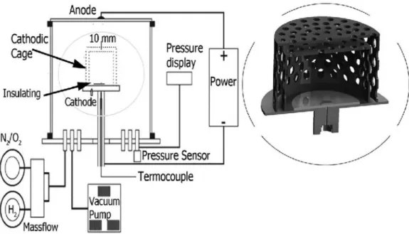
The system was the same as that used in plasma nitriding24,
with a vertically mounted cylindrical vacuum chamber (40
cm in diameter and 40 cm in height, made of stainless steel) was used, but with a cathodic cage as shown in Figure 1, with a power source having a maximum output voltage and DC current of 1500 V and 2 A, respectively. During the treatment there was a variation in the current and voltage of 0.75 to 0.78 mA / 522 to 535 V, 0.55 to 0.59 mA / 455 to 464 V and 0.55 to 0.58 mA / 455 to 462 V, for treatment temperatures of 300°C, 350°C and 400°C respectively. The gas mixture was introduced and its low rate adjusted using a four channels mass low controller MKS /247D. The
treatment pressure was measured by a BARATRON® Model
627D with a multichannel PDR 2000 / Mks.
Duplex stainless steel (UNS S31803) sheets, measuring
15x10x2 mm3 with a nominal composition of
22Cr-6Ni-3Mo-N were used after metallographic preparation and ultrasonic cleaning, as a substrate for titanium dioxide ilms deposition24. A double cage was adapted in order to
increase the deposition rate and involved the simple use of two concentric tubes of 75 mm x 55 mm and 45mm x 35mm (diameter x height) which formed the external and internal cages, in the coniguration shown in Figure 1.
The cages were manufactured using grade 2 titanium sheets with a 2 mm thickness. The tubes were covered on top by discs also made of titanium. Holes, 8 mm in diameter, with a distance of 9 mm from each other, were made in the cages walls. The substrate was then placed on top of an insulated disk and sample holder. The substrate, insulated disk and sample holder were placed inside the internal cage in order to keep them at a loating potential. The shortest distance between the sample (substrate) and the cage wall was 25 mm. The chamber cleaning was performed by injecting and evacuating argon gas three times before deposition.
The deposition was performed under conditions shown in Table 1, at temperatures of 300°C, 350°C, 400°C and deposition times of 1h, 2h and 4h for treatments performed
under a low of 6 sccm of Ar + 6 sccm of H2+ 3 sccm of
O2 under a working pressure of 150Pa. The low rate and
composition were optimized to produce a uniform layer
of TiO2 deposited on the substrate. Hydrogen (H2) was
introduced in order to control the oxidation process, thus avoiding the presence of some undesired oxides. This did not result in any signiicant change in the phase, and it is a common method to improve the surface properties of TiO2,
creating some defects (oxygen vacancies (OV) and Ti3+),
which are important for applications in photocatalysis30,31.
Figure 1: Schematic view of the ion nitriding reactor showing the spatial arrangement of the double cathodic cage.
Table 1: Temperature, deposition time and homologous temperature for treatments performed under a low of 6sccm of Ar + 6 sccm of H2 + 3 sccm of O2, and working pressure of 150 Pa.
Substrate Temperature (oC) Deposition time (h) Ts/Tm
Inox300T1H 300 1 0.27
Inox300T2H 300 2 0.27
Inox300T4H 300 4 0.27
Inox350T1H 350 1 0.29
Inox350T2H 350 2 0.29
Inox350T4H 350 4 0.29
Inox400T1H 400 1 0.31
Inox400T2H 400 2 0.31
Inox400T4H 400 4 0.31
3. Results and Discussion
Figure 2 shows the microstructure of both the surface and the cross section of the films deposited for 4h at different deposition temperatures. The roughness and thickness of the films increased with the increase of deposition temperature from 300oC to 400oC. These results
are in accordance with the growth model proposed by
Thornton27 that for 300oC and 400oC (T
s/Tm is 0.27 and
0.31, respectively), TiO2 films should present a columnar
structure with porous morphology. Grains are produced by low diffusion and low mobility of the atoms absorbed at the substrate surface.
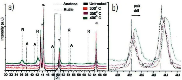
Figure 3 shows the XRD pattern for ilms deposited for 4h at diferent deposition temperatures. Compared to the untreated substrate, it shows that TiO2 was formed for all
treatment conditions. Further observation also shows that
the peak positions corresponding to the α and γ phases of the steel substrate with a shift towards higher angles(2θ), showing that there was a modiication at the substrate/ ilm interface, probably due to oxygen difusion, with the substrate forming a sub-layer or an interface layer between the substrate and the ilm (Figure 3b).
Analysis of the XRD spectra shows the onset of rutile phase formation at temperatures above 300°C for surface treatment times of 2h (Figure 4), although, for other conditions, the sensitivity of the XRD technique was not suicient to distinguish the two distinct structures with a good enough resolution. Using Raman spectroscopy (Figure 5) we can verify the change of the ilm structure from anatase to rutile as a function of sample temperature and treatment time. Even a very low amount of anatase TiO2 can be detected using
Raman spectroscopy, because of the high scattering factor of
such a phase32. We have found the presence of anatase and
Figure 3: (a) XRD pattern for ilms deposited at diferent temperatures during 4 hours and (b) peak shift detail for α and γ phase of the substrate.
Figure 4: XRD pattern for ilms deposited during 2h and diferent deposition temperatures showing the change of anatase to rutile phase.
that with a treatment time of 4 hours, for all temperatures, there is a predominance of rutile structure in the ilms. The case of a treatment at 400°C the rutile phase is found to be the predominant phase, and a very low amount of anatase (not detected in XRD) is present. For a treatment time of 2 h, rutile is found to be the majority phase conirming the onset predicted by XRD. At 300 ºC, anatase is the majority phase for up to 2 h of treatment (there is no sign of rutile phase at 1 and 2 h). After that, rutile is predominant with a very low amount of anatase phase present.
4. Conclusions
Our research shows that the use of the low cost cathodic cage (CC) technique, based on a multiple hollow cathode efect, allows TiO2 coatings on duplex stainless steel (UNS S31803)
Figure 5: Raman spectroscopy pattern for ilms deposited at 300ºC, 350ºC and 400ºC for diferent treatment times showing the change of anatase to rutile phase.
phase to be present are at temperatures lower than 300oC.
The results show that this simple and low cost technique can be applied over wide range of deposition parameters and is a good alternative for obtaining TiO2 ilms with the advantage
of a high degree of control of the properties and phases of the ilms. Furthermore, it is possible to obtain ilms on an economical, practical and versatile substrate, presenting elongated grains, with a columnar structure and a porous morphology which should increase greatly the possibility of its technical applications.
5. Acknowledgements
This work has been partially supported by the Brazilian agencies, CAPES and CNPq.
6. References
1. Diebold U. The surface science of titanium dioxide. Surface Science Reports. 2003;48(5-8):53-229.
2. Fujishima A, Hashimoto K, Watanabe T. TiO2 Photocatalysis:
Fundamentals and Applications. Tokyo: BKC Inc; 1999. 3. Fujishima A, Rao TN, Tryk DA. Titanium dioxide photocatalysis.
Journal of Photochemistry and Photobiology C: Photochemistry Reviews. 2000;1(1):1-21.
4. Zaleska A. Doped-TiO2: A Review. Recent Patents on Engineering.
2008;2:157-164.
5. Daviðsdóttir S, Canulescu S, Dirscherl K, Schou J, Ambat R. Investigation of photocatalytic activity of titanium dioxide deposited on metallic substrates by DC magnetron sputtering. Surface and Coatings Technology. 2013;216:35-45.
6. Malagutti AR, Mourão HAJL, Garbin JR, Ribeiro C. Deposition of
TiO2 and Ag:TiO2 thin ilms by the polymeric precursor method
and their application in the photodegradation of textile dyes. Applied Catalysis B: Environmental. 2009;90(1-2):205-212.
7. Evans P, Sheel DW. Photoactive and antibacterial TiO2 thin
ilms on stainless steel. Surface and Coatings Technology. 2007;201(22-23):9319-9324.
8. Xing MY, Zhang JL, Chen F. New approaches to prepare
nitrogen-doped TiO2 photocatalysts and study on their photocatalytic
activities in visible light. Applied Catalysis B: Environmental. 2009;89(3-4):563-569.
9. Yamakata A, Ishibashi T, Onishi H. Kinetics of the photocatalytic water-splitting reaction on TiO2 and Pt/TiO2 studied by time-
resolved infrared absorption spectroscopy. Journal of Molecular Catalysis A: Chemical. 2003;199(1-2):85-94.
10. Nowotny J, Bak T, Nowotny MK, Sheppard LR. Titanium dioxide for solar-hydrogen I. Functional properties. International Journal of Hydrogen Energy. 2007;32(14):2609-2629.
11. Tang H, Prasad K, Sanjinés R, Levy F. TiO2 anatase thin ilms
as gas sensors. Sensors and Actuators B: Chemical. 1995;26(1-3):71-75.
12. Karunagaran B, Rajenda Kumar RT, Viswanathan C, Mangalaraj D, Narayandass SK, Rao GM. Optical constants of DC magnetron sputtered titanium dioxide thin ilms measured by spectroscopic ellipsometry. Crystal Research and Technology. 2003;38(9):773-778.
13. Moafi HF, Shojaie AF, Zanjanchi MA. The comparison of photocatalytic activity of synthesized TiO2 and ZrO2
nanosize onto wool fibers. Applied Surface Science. 2010;256(13):4310-4316.
14. Sung YM, Kim HJ. Sputter deposition and surface treatment
of TiO2 ilms for dye-sensitized solar cells using reactive RF
plasma. Thin Solid Films. 2007;515(12):4996-4999. 15. Iida T, Takamido Y, Kunii T, Ogawa S, Mizuno K, Narita T,
et al. TiO2 thin ilms using organic liquid materials prepared by
Hot-Wire CVD method. Thin Solid Films. 2008;516(5):807-809. 16. Shan CX, Hou X, Choy KL. Corrosion resistance of TiO2 ilms
17. Benedix R, Dehn F, Quaas J, Orgass M. Application of Titanium Dioxide Photocatalysis to Create Self-Cleaning Building Materials. Lacer. 2000;5:157-168.
18. Ayieko CO, Musembi RJ, Waita SM, Aduda BO, Jain PK. Structural and Optical Characterization of Nitrogen-doped TiO2
Thin Films Deposited by Spray Pyrolysis on Fluorine Doped Tin Oxide (FTO) Coated Glass Slides. International Journal of Energy Engineering. 2012;2(3):67-72.
19. Sankapal BR, Lux-Steiner MCh, Ennaoui A. Synthesis and characterization of anatase-TiO2 thin ilms. Applied Surface
Science. 2005;239(2):165-170.
20. Georgieva J, Armyanov S, Valova E, Poulios I, Sotiropoulos S. Preparation and photoelectrochemical characterisation of electrosynthesised titanium dioxide deposits on stainless steel substrates. Electrochimica Acta. 2006;51(10):2076-2087.
21. Kment S, Kluson P, Bartkova H, Krysa J, Churpita O, Cada M, et al. Advanced methods for titanium (IV) oxide thin functional coatings. Surface and Coatings Technology. 2008;202(11):2379-2383.
22. Paulmier T, Bell JM, Fredericks PM. Development of a novel cathodic plasma/electrolytic deposition technique part 1: Production of titanium dioxide coatings. Surface and Coatings Technology. 2007;201(21):8761-8770.
23. Ferroni M, Guidi V, Martinelli G, Faglia G, Nelli P, Sberveglieri G. Characterization of a nanosized TiO2 gas sensor. Nanostructured
Materials. 1996;7(7):709-718.
24. Alves Jr. C, de Araújo FO, Ribeiro K, Costa JAP, Sousa RRM, de Sousa RS. Use of cathodic cage in plasma nitriding. Surface and Coatings Technology. 2006;201(6):2450-2454.
25. Quiñonez C, Vallejo W, Gordillo G. Structural, optical and electrochemical properties of TiO2 thin ilms grown by APCVD
method. Applied Surface Science. 2010;256(13):4065-4071. 26. Movchan BA, Demchishin AV. Structure and properties of thick
condensates of nickel, titanium, tungsten, aluminum oxide, and zirconium dioxide. Fizika Metallov I Metallovedenie. 1969;28:653-660.
27. Thornton JA. Inluence of apparatus geometry and deposition conditions on the structure and topography of thick sputtered coatings. Journal of Vacuum Science & Technology. 1974;11(4):666-670.
28. Alfonso E, Olaya J, Cubillos G. Thin Film Growth Through Sputtering Technique and Its Applications. In: Andreeta MRB, ed. Crystallization - Science and Technology. Rijeka: InTech; 2012. 578 p.
29. Daudt NF, Barbosa JCP, Braz DC, Alves Jr. C. TiN thin ilm deposition by cathodic cage discharge: efect of cage coniguration and active species. Journal of Physics: Conference Series. 2012;406:012021.
30. Liu H, Ma HT, Li XZ, Li WZ, Wu M, Bao XH. The enhancement of TiO2 photocatalytic activity by hydrogen thermal treatment.
Chemosphere. 2003;50(1):39-46.
31. Xiong LB, Li JL, Yang B, Yu Y. Ti3+ in the Surface of Titanium Dioxide: Generation, Properties and Photocatalytic Application. Journal of Nanomaterials. 2012;2012:831524.
32. Beuvier T, Richard-Plouet M, Brohan L. Accurate Methods
for Quantifying the Relative Ratio of Anatase and TiO2(B)