© 2016 IBRACON © 2016 IBRACON
Automatic procedure for analysis and geometry
deinition of axisymmetric domes by the membrane
theory with constant normal stress
Processo automático para análise e deinição de
geometria de cúpulas axissimétricas pela teoria
de membrana com tensões normais constantes
a Instituto Federal de Santa Catarina, Departamento de Construção Civil, Florianópolis, SC, Brasil; b Universidade Federal de Santa Catarina, Departamento de Engenharia Civil, Florianópolis, SC, Brasil. Received: 28 Jul 2015 • Accepted: 16 Jan 2016 • Available Online: 12 Jul 2016
F. T. RABELLO a
N. A. MARCELLINO b [email protected]
D. D. LORIGGIO b [email protected]
Abstract
Resumo
This paper presents an automatic procedure using the membrane theory of shells to analyse and deine geometries for axisymmetric domes sub -jected to its own weight, varying its thickness and bend radius, to obtain constant normal stresses along the structure. The procedure ofers a great advantage over the analytic solution of the problem and usual shell numerical methods when one wants to determine the dome geometry with constant stresses, since the presented procedure has the goal stress as input value for obtaining the geometry, as opposed to the usual numerical methods, where the reverse occurs. An example clariies the diferences between a spherical dome with constant thickness and a dome subjected to constant stress. The convergence of the method for a speciic material weight and stress for a dome are also presented.
Keywords: domes, thin shells, membrane theory, meridional stress, tangential stress.
Este artigo apresenta um processo automático para análise e deinição de geometria pela teoria de membrana para cúpulas de revolução axissi -métricas submetidas ao peso próprio, com variação de espessura e raios de curvatura, de modo a obter tensões normais tangenciais e meridio -nais constantes em qualquer ponto da estrutura. O processo apresenta grande vantagem sobre a solução analítica do problema e a por métodos numéricos usuais de casca quando se deseja determinar a geometria da cúpula em função de apenas uma tensão solicitante constante, uma vez que o processo tem como dado de entrada a própria tensão inicial para obtenção da geometria, diferente dos métodos numéricos usuais, onde ocorre o inverso. Um exemplo explicita as diferenças entre uma cúpula esférica com espessura constante e uma cúpula com tensões constantes submetida ao peso próprio. A veriicação da convergência do método para uma tensão solicitante e peso especíico do material de uma cúpula também são apresentados.
1. Introdução
Thin shells are curved laminar structures, whose thickness is small when compared to its other dimensions. These elements may be subject to membrane and bending stresses, depending on its re-straints and loadings. Axisymmetric loading structures with proper restraint coniguration can display only membrane stresses that act in parallel to a plane tangent to the mean surface of the shell at a given point, which can be considered the stresses equalty distributed throughout its thickness.
Shells are a type of structure that has a wide range of applications , including, for example, fuselages of airplanes and submarines, metal silos, sheds covers, building structures, automotive and aerospace components, pressure vessel , liquid tanks, missiles and, among others, domes.
Domes are semi-spherical or similar form shells, which structure may consist of various materials and their varied uses and archi-tectural conceptions refer back to prehistory.
Among the advantages of the use of domes, may be mentioned the possible large spans to be covered, low weight, high stifness and the possibility of geometric handling in their design, which in many cases make them architecturally beautiful. Constructive diiculties and the high costs may be mentioned often as drawbacks [8].
The construction of the irst technically advanced domes began in Europe with the Roman Architectural Revolution, when such struc-tural system was often used to shape large interior spaces of tem-ples and public buildings [12]. The material typically used in these domes construction did not have great tensile strength, so, in order to reduce its weight, the thickness and aggregate material would vary as height increased, and thereby reduce regular stress in the direction of the meridians in the completed structure. One example is the Pantheon in Rome (Figure 1), originally built in 27 BC. With 43.4 meters porthole, the Pantheon in Rome remained the world’s largest dome for more than a millennium and is currently the larg-est dome in the world made of non-reinforced concrete.
The geometry of the domes directly inluences its structural per -formance. Therefore, for a given material having certain charac-teristics, structural eiciency is directly related to the eiciency of its shape, including its thickness and radii of curvature. There is a trend of research in the pursuit of optimization of the geometry of this type of structure, as can be seen in [1], [2], [3], [4] e [7]. One of the main factors for this interest are the advances and accessibility of computers and the development of numerical models and opti-mization algorithms for solving such problems [1]. Solutions for nu -merical methods with optimization algorithms are suitable for more general cases of geometries and loads, while there is still a con-lict between the computational cost, the accuracy of the results
546 IBRACON Structures and Materials Journal • 2016 • vol. 9 • nº 4
obtained and the mathematical complexity of the solutions [3]. The approach can also present some convergence problems, which some analyzes have values of stresses or displacements that are not even found in the ield of real numbers [3].
This paper proposes an automatic process for the analysis and deinition of thin shells segments revolution geometry (domes) submitted to its own weight by membrane theory with thickness and radii of curvature variation in order to obtain meridional and tangential stresses constant by a process of simple implementa-tion and low computaimplementa-tional cost. The process has advantage over the usual numerical methods bark, such as the inite element method, when it is desired to determine the geometry of the dome due to a constant stress, since the process has its own initial ten-sion as input to obtaining geometry, diferent from the usual numer -ical methods, where the reverse occurs. Furthermore, the exact analytic solution of the problem is extremely diicult, as shown in methodology, which makes the presented process quite interesting for solving such structures. A dome with constant meridional and tangential stresses tends to provide a design with a good use of the material across the dome and decrease bending moments and shear stresses that may be signiicant for other types of geometry. According to the membrane theory, the stifness to lexure and torsion in the shell should not be considered, which causes the bending and torsional moments to resulting null. Under these con-ditions, also only normal and tangential forces will request cancel each other out the shear forces and the shell. For this theory to be valid, it must meet the following conditions:
n The law of variation of the mean surface curvature is continuous; n The law of variation of the thickness of the shell is continuous; n The distribution of loads applied on the surface is continuous; n The forces applied to the free edges act in the corresponding
planes tangent to the mean surface;
n Support reactions are contained in tangent planes to the mean surface.
Lamé, French engineer whose solution is sometimes also called the Lamé problem, originally settled the general solution of the
axi-symmetric revolution cylinder thick walls problem in 1833. The initial solution was based on a cylinder subjected to internal pressure, which is made use of linear relationships of Hooke’s Law. The formulation presented in this paper considers only the equilibrium equations of the domes. Thus, no material property is used and its use is not restricted to elastic materi-als. However, these equations are valid for situations where the thickness of the dome does not exceed 10% of the internal radius, remaining the error rate small [15]. Using Lamé equa-tions and the ones presented in this work , it can be seen by Figure 2, the variation in tangential stress
σ
θ of revolution walls shells subjected to internal pressurep
, when there are revolution shells with a thickness equal to 10 % of the inner radius and the thickness of the cylinder is equal to 400 % of the inner radius.1.1 Objective
The objective of this paper is to present a process using the mem-brane theory for analyzing and deining the geometry of an axisym -metric dome subjected to its own weight, with varying thickness and curvature radii, in order to obtain constant normal and shear stresses.
2. Method
2.1 Equilibrium equations
In the case of domes studied in this work, it is presented the equi-librium equations of the membrane theory for thin shells subjected to loads with revolution symmetry. For such structures, due to its symmetry, the following characteristics are presented:
( )
=
N
θN
θθ
;0
=
=
N
jθN
θj ;( )
=
p
jp
jj
;0
=
p
θ ;1 http://www.mathworks.com - Student version.
2 Licensed Software to Santa Catarina Federal University. Mix System is a system developed by Engineer Ricardo Sergio Pinheiro Medeiros and marketed by TQS Informática Ltda.
Figure 2 – Variation of the tangential stresses on the wall of the revolution
( )
=
z zp
p
j
. where:N
j – Normal force per unit of length in the direction of the merid-ian;N
θ – Normal force per unit of length in the direction parallel;,
N
jθN
θj – shear forces per unit of length;p
j – Loading tangent to the surface of the shell in the direction of the meridian;p
θ – Loading tangent to the surface of the shell in the direction parallel;z
p
– Loading perpendicular to the surface of the shell.It’s possible to completely deine the geometry of a dome by its thickness
h
and the radii of curvaturer
1 andr
2 arbitrarily vari-able (Figure 3). The radiusr
2 has its center of curvature lo-cated on the axis of the shell and it generates the surface of the shell in the perpendicular direction to the tangent to the meridian. On the geometry of the shells, one can also deine the radiusr
0, which lies in a plane perpendicular to the axis of the shell and has a proportion tor
2 equal tor
0=
r
2.sen
j
. It is assumed that the thicknessh
is very small compared tor
1 andr
2 and therefore no distinction is made between the inner, middle and outer radii of the dome.Due to the symmetry of the dome there is an axisymmetric load condition. This leads the structure to have tangential constant forces
N
θ on each side of the ininitesimal element of the dome surface, which does not occur with the meridional forceN
j. The shear forcesN
jθ andN
θj are canceled due to the symmetry of the problem.The ininitesimal element of the surface of the dome on Figure 2 is subjected to external forces in the direction of the meridian (
p
j) and in the normal direction to the surface (p
z is positive entering the dome).Using the equation:
(1)
r0=r2. sen
φ
On the upper side of the element:
(2)
N
φr
0d
φ
=N
φr
2. sen
φ
d
φ
and on the inferior side
(3)
(
N
φ+
∂N
∂φ
φdφ
((
r
0+
dr
dφ
0dφ
(
dθ
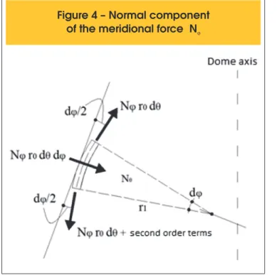
As these forces are not collinear (Figure 4), a component appears in the direction z equal to:
(4)
N
φr
0dθdφ
548 IBRACON Structures and Materials Journal • 2016 • vol. 9 • nº 4
In the parallel direction, the forces on the element right and left are also not collinear (Figure 5), therefore a component force appears.
(5)
N
θr
1dφdθ
This force is horizontally projected in the mean plan of the dome. Projecting this force in the direction tangent to the meridians:
(6)
N
θr
1d
φ
d
θ
cos
φ
And in the normal direction to the mean surface:
(7)
N
θr
1d
φ
d
θ
sen
φ
Taking the sum of the forces in the tangent direction to the me-ridian in equations (2), (3) and (6) equal to zero, neglecting sec -ond order terms and dividing the equation by
d d
j θ
, equation (8) is shown:(8)
d(Nφr0)
d
φ
-Nθr1
cos
φ
+pφr0r1=0
Taking the sum of forces in the normal direction to the surface in
equations (4) and (7) equal to zero and dividing the equation by
d d
j θ
andr r
1 2sen
j
:(9)
N
φr
1+
N
θr
2=-p
zOne can determine the unknown forces on the membrane by means of free-body analysis of whole shell, over a parallel circle. From equation (9) writes the equation (10):
(10)
Nθ=-pzr2-
Nφ
r1
r2
Figure 4 – Normal component
of the meridional force N
jFigure 5 – Normal component
of the tangential force N
qMoreover, substituting (10) into (8), one has:
(11)
d(N
φr0)
d
φ
-
(
-pzr2-N
φr1
r2
)
r1
cos
φ
=-p
φr0r1
Substituting (1) into (11) and multiplying by
sen
j
:(12)
d(N
φr
0)
d
φ
sen
φ
+N
φr
0cos
φ
=
-p
zr
1r
2sen
φ
cos
φ
-p
φr
1r
2sen²
φ
where Therefore:
(13)
d
d
φ
[(N
φr
0) sen
φ
]=-r
1r
2sen
φ
(p
zcos
φ
+p
φsen
φ
)
Integrating both sides of equation (13):
(14)
N
φr
0sen
φ
-F(
φ
)-C=0
where:
( )
=
∫
1 2sen
(
zcos
−
sen
)
+
F
j
r r
j
p
j
p
jj j
d
In the case of domes without an opening at the top, the constant C is zero. So, multiplying (14) by
2
p
:(15)
2
π
r0N
φsen
φ
-2
π
F(
φ
)=0
The vertical resultant force
R
due to loadingsp
z andp
j is kept in balance by the vertical component of theN
j force. The resultant forceP
(Figure 6) for domes without openings on top is given by:(16)
P=2
π
∫ r
1r
2sen
φ
(p
zcos
φ
+p
φsen
φ
)d
φ
φ0
By substituting (16) into (15) and isolating
N
j:(17)
N
φ=
2
π
r
P
0
(
φ
) sen
φ
One can thus determine the membrane forces in axisymmetric shells of revolution. The support conditions of the domes should always be tangential to
N
j, as shown in Figure 7.From Figure 7 it can be seen that only a vertical component
V
does not satisfy the equilibrium condition. It’s possible to cancel the horizontal component
H
. with the addition of a resilient ring for example. However, the adoption of such device causes signiicant local lexure stresses, which will not be addressed in this paper.2.2 Spherical dome
For the analysis of a spherical dome subjected to own weight is considered constant thickness h and the radius of curvature
r
1=
r
2. Consider, therefore, a radius of spherical domer
1= =
r
2a
and constant thicknessh
subjected to own weight, withj
ranging from 0º to 90º. The resultantP
is given byp
(own weight force per unit of area) multiplied byA
(ininitesimal section area), whereA
is given by:0
2
=
∫
⇒
=
A
dA
dA
p
r ds
0 0
2
sen
2
² sen
=
∫
⇒
=
∫
A
a
a d
A
a
d
j j
p
j j
p
j j
The resultant being
P
=
p A
.
, one can obtain the expression (18):(18)
P=p
2
π
a² ∫ sen
0φφ
d
φ
⟾
P=-2
π
pa²(1- cos
φ
)
By substituting equations (18) and (1) in (17), meridional force is:
2
²(1 cos )
2
²
−
−
=
pa
N
a sen
j
p
p
j
j
550 IBRACON Structures and Materials Journal • 2016 • vol. 9 • nº 4
(1 cos )
(1 cos )
∴
= −
= −
+
+
ap
ap
N
ou
h
j
j
σ
jj
In (9) is given:
= −
z−
N
θp a
N
j(
)
cos
1 cos
∴
N
θ= −
p
j
a
+
+
ap
j
By solving the equations above, one can obtain the tangential forc-es of the spherical dome:
(
1
)
cos
(
1
)
cos
1 cos
1 cos
=
+
−
=
+
−
ap
N
ap
ou
h
θ
j
j
σ
θj
j
Assuming a thickness , e
p
=
0, 0236 /
N cm
²
, it’s possible to draw of meridional and tangential forces diagrams in function ofj
. The results are shown in Figure 8.Figure 8 – Tangential forces N and meridional forces N in function of
q jj
on the spherical dome
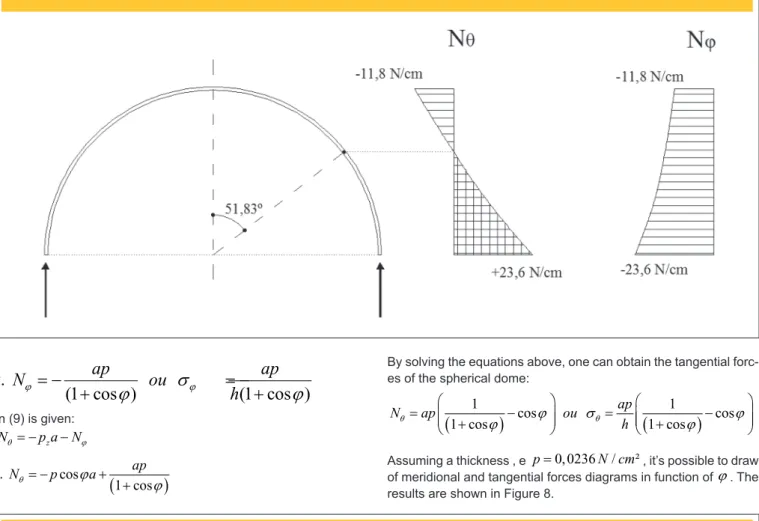
It is noticeable that from
j
=
0
toj
=
51.827
o, no traction force develops at the dome, only compressive forces.
Solving the problem using the inite element method, we obtain a maximum compression force equal to 11,983 N/cm² and trac-tion equal to 26,243 N/cm². The
j
angle at which no shear stress develops in the direction parallel dome is approximately 52º. The stress diagram is shown in Figure 9.2.3 Constant stresses dome
On the constant stress dome analysis, it is considered a dome with variable thickness subjected to own weight
p
.On such domes, should not only their thick- ness vary along the height but also their radii of curvature, so that the meridional and tangential stresses are equal and constant.
The weight per unit of area in the central plane of these summits is given by:
(19)
p=γh
Therefore,
p
z andp
j components are given by:(20)
p
z=
γ
h cos
φ
p
φ=
γ
h sen
φ
In the case of domes with constant stresses, the geometry of the meridian is determined in such way that the meridional compres-sive stresses are constant and equal to
σ
in all directions in its mean plane, with:=
= −
N
jN
θσ
h
By replacing in (9):
(21)
σh.
(
r
1
1
+
1
r
2)
=γh cos
φ
By replacing (1) and isolating .
(22)
1
=
γ
r
0σ
r
0cos
φ
- sen
φ
From Figure 10 is possible to deduce the following relationship:
(23)
ds=r
1d
φ
r
1d
φ
=
cos
dr
0φ
Replacing (23) in (22):
(24)
dr
0d
φ
=
r
0cos
φ
γ
σ
r
0cos
φ
- sen
φ
Integrating both sides of equation (24):
0 0 0 0
cos
cos
sen
=
−
∫
r
r
d
r
jj
j
γ
j
j
σ
It’s obtained:(25)
r
0=-r
0σ
2(σ
2+γ
2.r
02) .ln
[
γ.r
0.tan
(
φ
2
)
2
-( )
γ.r
0+2.tan
φ
2 .
σ
]
+r
0σ
2(σ
2+γ
2.r
02) .
[
(
)
]
(
)
ln 1+tan
φ
2
2+2
(σ
2+γ
σ
22.r
02
) .
γ.r
0 2.
φ
2
On top of the dome, where
j
=
0
, the right side of equation (24) becomes undeined. To solve this problem is necessary to use equations (21) and (23). As on the top of the domer
1=
r
2, it fol-lows that :1 2 0 1
2
2
= =
=
=
r
r
σ
dr
r d
j
σ
d
j
γ
γ
Therefore, on the top of the dome:
552 IBRACON Structures and Materials Journal • 2016 • vol. 9 • nº 4
(26)
dr
0dφ
=
2σ
γ
Then, the shape of the meridian of the dome with constant stress-es can be deined by equations (24) and (26) . The variation of the thickness of the dome can be determined by the equations (8) and (20) , which are obtained by dividing the equation for:
(27)
-
d
d
φ
(hr
0)+hr
1cos
φ
+
σ
γ
hr
1r
0sen
φ
=0
For
j
=
0
, we obtain the equation (27) :( )
00
n
1=
dr
d
hr
hr
h
d
j
d
j
Replacing (22) into (27) it follows that:
(28)
d
dφ
(hr
0)=hr
0cos
φ
+
σ
γ
r
0sen
φ
γ
σ
r
0cos
φ
- sen
φ
By integrating both sides from
0
aj
:(29)
h.r
0=h.r
0.ln
[
1+tan
(
φ
2
)
[
(
)
2
]
-h.r
0.ln
γ
.r
0.tan
φ
2
2( ) ]
-
γ
.r
0+2.tan
φ
2 .
σ
It’s possible to then determine the thickness of the dome with constant stresses by equations (27) and (28).
The equations (25) and (29) were obtained by MathCAD computer soft-ware. However, because of those functions, whose integrals are not easy to get an analytical solution, it’s possible to use numerical integra-tion for its determinaintegra-tion, in order to calculate the approximate value of deinite integrals using, for example, the trapezoidal rule and Simpson’s Rule [10]. One can get the radius of curvature
r
1 andr
2 by simpler iterative process, presented by [5].Equation (26) determines the radius at the top of the dome, as it follows:
1 2
2
= = =
topor
r
r
σ
γ
Rearranging (21):(29)
h.r
0=h.r
0.ln
[
1+tan
(
φ
2
)
[
(
)
2
]
-h.r
0.ln
γ
.r
0.tan
φ
2
2( ) ]
-
γ
.r
0+2.tan
φ
2 .
σ
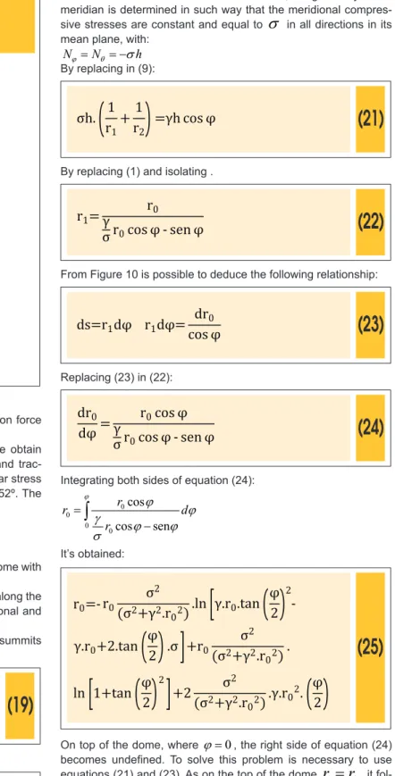
Knowing the radius of curvature at the top, one can start the de-termination of the dome geometry with constant stress, as shown in Figure 11.
A gradual graphic built can be made using equation (30) starting from the top radius
r
topo, then following the points A, B, C , etc.Initially ,the arc from the point O to point B is drawn. At point B the new weight
p
z is calculated by equation (30), and beingr
2=
AB
, one can determine a new curvature radius
r
1 that results greaterthan the previous radius of curvature
r
1. The extension of the new 1r
withinr
2 has a new center C, which have a new curvature,larger than the previous one. The iteration of the geometry must be made with approximately equal
Dj
. The lower theDj
, the closer will the values obtained in relation to the exact solution be. It can be seen from equation (30) the shape of the meridian is determined solely by the stress that is desired as set constant and the speciic weight of the material used. Figure 12 showsFigure 11 – Graphic determination of the
geometry of the dome with Constant stress [5]
axis of the surface of a dome subjected to own weight with con-stant stress
σ
=
20 /
N cm
²
and the speciic weight of the material0, 0236 /
²
=
N cm
γ
, withj
up to 70°.The proposal automation, based on iterative process shown by [5], is made by taking up the triangle ACE in Figure 12, shown in Figure 13. Once
r
topo is calculated, one chooses aDj
for determining radiir
2,r
1,r
2,n, and so forth . The radiusr
2,n is given by:(31)
r2,n= r1-u
where
( )
Δ
[ ]
(
( )
Δ
)
1
.Δ
ì
é
ù
ü
ï
ï
=
í
+ ¸
ê
+
ú
ý
ê
ú
ï
ë
û
ï
î
þ
tan
u sec
s t
tan n
j
j
j
The value of
n
refers to the iteration in which it is determined the value ofr
2.The geometry of the meridian can be obtained with no dependence on the thickness
h
, using only the equation (30). However, unlike other thin shells of revolution, as the cylinder or closed reser-voirs, the use alone of this equation is not suicient to establish a condition of constant stress across the dome.To determine the variation of the thickness ong the dome height, an ininitesimal element of the mean shell surface with side
ds
must be considered, as shown in Figure 14.
It is observed from Figure 14 that the presence of a load in the direction of the meridian requires a force to equilibrate it, thus it is imperative to have have an increase
dh
on the lower side of the ininitesimal element.The approximate equilibrium equation of the forces on the merid-ian of the dome can be obtained in Figure 14 and is given by:
(
)
2
sen
0
+
−
+
=
hds
hds
h
dh ds
σ
γ
j σ
Or by dividing the equation by
ds
:sen
=
dh
hds
σ
γ
j
In Figure 14 it is seen that
ds
sen
j
=
dl
, wheredl
is the variation in vertical height of the dome, starting from its top. Then :(32)
dh
h =
γ
σ
dl
Integrating (32):
(33a)
ln
h
=
g
l
+
s
C
or
(33b)
0
=
l=
lh
C
e
gsh e
gs0
h
being the thickness of the dome at the top , wherel
=
0
.Figure 13 – Triangle ACE for
the process automation
554 IBRACON Structures and Materials Journal • 2016 • vol. 9 • nº 4
Figure 15 shows a dome subjected to its own weight with constant stress. From equations (27) and (33), it is observed that the thick-ness at the top of the dome is not dependent on any external fac-tor, so
h
0 may have any initial value, since it depends only on itsown weight.
The automation of calculation
h
can be performed using Figure 13, wherein for each value ofj
,l
can be obtained by:(34)
l
n=r
topo+
Σ
in=1v
n-r
2,n.cos(n.
Δφ
)
where
n
is the iteration number for the value ofl
for the cumulativeDj
.3. Results
3.1 Dome with constant stress
To explain the differences between spherical domes with uni-form thickness and domes with constant tensions subjected to own weight, an example for comparison is presented.
The dome with constant stress
σ
=
20 /
N cm
2 (compression in both directions) has a thickness at the toph
0=
10
cm
, spe-cific weightγ
=
0, 0236 /
N cm
3, which results in a initial radius of curvature at the topr
1= =
r
2r
topo=
1.695
cm
. The anglej
ranges from 0° up to 60°, withDj
equal to 0.1°.The spherical dome has a constant thickness
h
=
10
cm
and its radius of curvature is equal to the top radius of curvature of the dome with constant stresses (r
=
1.695
cm
). The specific weight isγ
=
0, 0236 /
N cm
3, which anglej
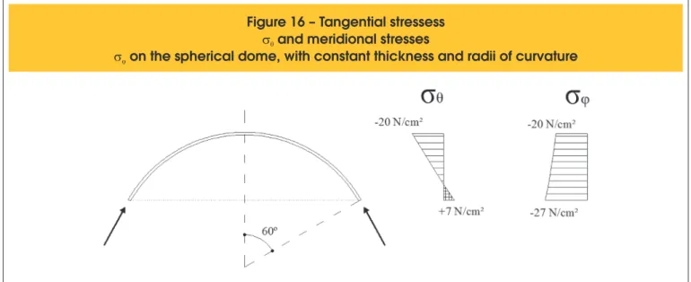
also varies from 0° up to 60°.Figure 16 shows the stresses diagram developed in the spher-ical dome. Figure 17 and Table 1 show the variation of the thickness and radius of curvature
r
1 andr
2 along the dome height with constant stresses.The meridian and the thickness of the two domes (scale 2: 1 for the radius of curvature ) are shown in Figure 18.
It is noticed that, in the example, the spherical dome has higher compressive stresses along
j
, and tensile stresses in the directionθ
. As theγ σ
/
ratio is very small, even when considering a conservative stress, the dome radii of curvature with constant stress always increases asj
increases, which means that domes subjected to their own weight are higher in relation to equivalent spherical domes with equal initial radius when considering the same . but smaller in height when con-sidering the samer
0. This is repeated for virtually all materi-als used in construction. Because there are only compression stress, the use of materials not resistant to traction is pos-sible, and the conditions necessary to support the dome are improved. Furthermore, the fact that there is only one solicitant stress value in the two axes, leads to an increased structural performance of the dome due to the better utilization of theFigure 15 – Variation of the thickness
h (h < h ) em uma cúpula
topo basecom tensões constantes
Figure 16 – Tangential stressess
s
qand meridional stresses
material.
The initial thickness of the dome with constant stress
h
0 is multiplied bye
asj
increases by a factor ofγ σ
/
. It is no-ticed that the inverse relationγ σ
/
is equal to half ofr
topo. Thus,h
0 increases exponentially in function ofj
whenl
is greater thanr
topo/ 2
, as shown in Table 1 withj
≥ °
50
.3.2 Convergence process and limits of
geometry
The results obtained by the process are dependent on the in-put data initial stress
σ
, specific weight of materialγ
and integration stepDj
. The higher the valueDj
, the lower the quality of the values obtained. Figure 18 shows the conver-gence ofr
1 asDj
is reduced for the dome of the previous example withj
= °
60
.It can be seen that with
Dj
close to 0,1°, the radius of cur-vature of the results begin to converge . The same is seen in Figure 20 for the thicknessh
, which convergence is also true withDj
close to 0,1°. In other simulations, this same value ofDj
seemed suitable for the convergence of the results.In order to make the formulations of the membrane for domes valid, the conditions must be met:
(35)
h
≤
0,1.r
0as shown in Figure 2. Figure 21 shows the convergence of the maximum angle
j
as a function ofDj
, to meet the relation (35) .It is observed that around
Dj = 1
º
there is already a conver-gence to the maximum value ofj
to meet the validity of the membrane model in the example shown. The maximum value ofj
is dependent on the initial stress and the specific weight of the material, therefore variable.4. Conclusions
This paper presents an automatic process to deine the geome -try of axisymmetric domes subjected to their own weight by the
Figure 17 – Thickness and radii of curvature of the dome with constant stress
Table 1 – Geometry of dome with constant stress in function of
j
with
Dj
= 0,1º
Angle
j Height l (cm)
Thickness h (cm)
Radius of curvature r1 (cm)
Radius of curvature r2 (cm)
0º 0 10,0 1695 1695
10º 21 10,3 1728 1704
20º 107 11,6 1866 1745
30º 252 13,5 2123 1815
40º 485 17,7 2601 1925
50º 853 27,4 3566 2092
60º 1492 58,2 6022 2359
556 IBRACON Structures and Materials Journal • 2016 • vol. 9 • nº 4
membrane theory with varying thickness and radii of curvature, in order to obtain constant meridional and tangential stresses. The results show that domes subjected to own weight generally have greater heights than the equivalent spherical ones with the same initial radius for the same
j
, but have lower heights for the samer
0 due to the relationshipγ σ
/
being so small. Therefore, even when for a conservative initial stress, the radii of curvature of the dome with constant stress always increase asj
increases.Regarding the presented process, it is clear that the accuracy of the results is a function of
Dj
. For diferent conigurations ofγ
andσ
, it was found that the convergence of results starts with values ofDj
below 0,1°. For the validity of the membrane model, it is assured that the equation (35) is respected in order to keep the error of the variation of normal stress along the thickness of the dome small. The convergence in the example shown was aroundj
= 69º, though this value varies with the initial data used for the dome with constant stress.The automatic process proposed to deine the geometry of axi
-Figure 19 – Convergence of r
1in function of
Dj
for
j
= 60º
Figure 18 – Spherical dome and dome with constant stress
Figure 21 – Convergence of the limit value
of
j
for the validity of the membrane model
symmetric domes with constant stress subjected to own weight is simple to use and has a great advantage over the usual numeric methods. The process shown is also quite interesting for solving such structures as the analytical solutions to the problem are not easy to obtain. The tool is shown to be adequate, therefore, for the geometry deining of domes with constant stress for subse -quent design.
5. Referências bibliográicas
[1] ABDESSALEM, J. FAKHREDDINE, D. SAID, A. MOHAMED, H. Shape optimization for a hyperelastic axisymmetric struc -ture. Journal of Engineering, Design and Technology, v.12, n.2, 2014; p.177-194.
[2] BLETZINGER, K.U. WÜCHNER, R. DAOUD, F CAMPRUBÍ, N. Computational methods for form inding and optimization of shell and membranes. Computer Methods in Applied Me-chanics and Engineering, v.194, n.30, 2005; p.3438-3452. [3] CAMPUBRÍ, N. BISCHOFF, M. BLETZINGER, K.U. Shape
optimization of shells and locking. Computers and Struc -tures, n.82, 2004; p.2551-2561.
[4] ESPATH, L.F.R. LINN, R.V. AWRUCH, A.M. Shape optimiza -tion of shell structures based on NURBS descrip-tion using automatic diferentiation. Internatiotnal Journal for Numerical Methods in Engineering, v.88, n.7, 2011; p.613-636. [5] HARTOG, J. P. D. Advanced Strength of Materials.
McGraw-Hill Book Company, New York, 1952, 401 p.
[6] ITALY’S best, The Pantheon. Disponível em <http://www.italys -bestrome.com/the-pantheon/> Acesso em 27 de julho de 2015. [7] KIENDL, J. SCHMIDT, R. WÜCHNER, R., BLETZINGER,
K.U. Isogeometric shape optimization of shells using semi-analytical sensitivity analysis and sensitivity weighting. Com-puter Methods in Applied Mechanics and Engineering, v.274, 2014; p.148-167.
[8] LINN, R. V. Otimização de forma de cascas axissimétricas utilizando diferenciação automática. Monograia de gradu -ação. UFRG. Porto Alegre, 2010, 92 p.
[9] MARK, R. HUTCHINSON, P. On the structure of the Roman Pantheon. College Art Association. The Art Bulletin. Vol. 68, No. 1, p. 24-34. Março de 1986.
[10] POPOV, E. P. Introdução à Mecânica dos Sólidos. Editora Edgard Blücher Ltda. São Paulo, 1978, 534 p.
[11] POPOV, E. P. Engineering Mechanics of Solids. Prentice-Hall. New Jersey, 1999, 891 p.
[12] Rasch, J. The Dome of the Roman Architecture. Develop-ment, Design, Construction. Architectura 15; p. 117–139. 1985.
[13] TIMOSHENKO, S. P. GERE, J. M. Mecânica dos sólidos, v.1. LTC. Rio de Janeiro, 1983, 258 p.
[14] TIMOSHENKO, S. P. GOODIER, J. N. Theory of Elasticity. McGraw-Hill Book Company, Nova Yorque, 1951.
![Figure 1 – Section of the Rome Pantheon dome [6]](https://thumb-eu.123doks.com/thumbv2/123dok_br/18861181.417955/2.892.73.829.572.1130/figure-section-rome-pantheon-dome.webp)
![Figure 2 – Variation of the tangential stresses on the wall of the revolution shells, due to internal pressure in function of their thickness [11]](https://thumb-eu.123doks.com/thumbv2/123dok_br/18861181.417955/3.892.61.830.777.1164/variation-tangential-stresses-revolution-internal-pressure-function-thickness.webp)
![Figure 14 – Meridional equilibrium of an infinitesimal element of the dome [5]](https://thumb-eu.123doks.com/thumbv2/123dok_br/18861181.417955/10.892.68.443.173.656/figure-meridional-equilibrium-infinitesimal-element-dome.webp)