INVESTIGATIONS ON THE ACCURACY OF THE NAVIGATION DATA OF
UNMANNED AERIAL VEHICLES USING THE EXAMPLE OF THE SYSTEM
MIKROKOPTER
M. Bäumker, H.-J. Przybilla*
Bochum University of Applied Sciences, Lennershofstr. 140, D-44801 Bochum, Germany - (manfred.baeumker, heinz-juergen.przybilla)@hs-bochum.de
Commission I, WG I/V
KEY WORDS: UAVs, Photogrammetry, Navigation, Sensor Orientation, Flight planning
ABSTRACT:
Bochum University of Applied Sciences (HS BO) is currently involved in an UAV project, whose fundamental developments are the result of an internet community. The MikroKopter system, being built by the laboratory, is a manually and autonomous flying platform. With regard to the implementation of an autonomous flight the MikroKopter is equipped with appropriate sensors for the flight control. The interaction of these components allows horizontal and vertical stabilized positioning of the system, as well as the return to the launch site. Using these positioning data a stabilization and orientation of the camera occurs, followed by a manual or automatically triggering of the camera to the predetermined positions. All flight data is completely recorded and can be evaluated at a later date.
Investigations to the quality of navigation data are presented. Based on different flights at the Bochum test field, combined with the use of alternative navigation sensors, an evaluation of the standard components of the MikroKopter system occurs. Another focus is given by efforts to optimize the control, stabilization and orientation of the camera.
KURZFASSUNG:
Die Hochschule Bochum (HS BO) beteiligt sich aktuell an einem UAV-Projekt, das in seinen grundlegenden Entwicklungen die Ergebnisse einer Internet-Community darstellt. Mit dem im Labor aufgebauten MikroKopter steht eine leistungsfähige, manuell und autonom fliegende Plattform zur Verfügung. Im Hinblick auf die Durchführung eines autonomen Flugs ist der MikroKopter mit entsprechenden Sensoren für die Flugregelung ausgestattet. Das Zusammenwirken dieser Komponenten ermöglicht eine lage- und höhenstabilisierte Positionierung des Systems, ebenso wie die Rückkehr zum Startplatz. Sämtliche Flugdaten werden vollständig aufgezeichnet und können zu einem späteren Zeitpunkt ausgewertet werden.
Im Beitrag werden Ergebnisse zur Qualität der Navigationsdaten des Systems vorgestellt, da diese wesentlichen Einfluss auf die Geometrie photogrammetrischer Bildverbände nehmen. Auf der Grundlage von Testfeldbefliegungen sowie der Nutzung alternativer Navigationssensoren erfolgt eine Bewertung der Standardkomponenten des MikroKopter-Systems.
* Corresponding author.
1. INTRODUCTION
1.1 Motivation
Unmanned Aerial Vehicle (UAV) are meanwhile tested and used for several decades and varying applications (Przybilla & Wester-Ebbinghaus, 1979, Wester-Ebbinghaus, 1980, Eisenbeiss, 2009). Concerning military use these systems are established for a long time, but meanwhile also civil utilisation becomes more and more important. The presented „MikroKopter“ system had been (and still is) developed under the assistance of an internet community (MikroKopter, 2011). All electronic components used are standard products, fixed together to an efficient and low-prize UAV. The main focus for using the copter at HS BO are photogrammetric applications. These requirements derive the enforcement of high quality images and precise nagivation.
1.2 Aims
With regard to the implementation of an autonomous flight the MikroKopter is equipped with appropriate sensors. These include, in addition to the flight control, mandatory micro-mechanical gyroscopes and accelerometers, the so-called Navi-control, a 3-axis magnetic sensor, a barometric pressure sensor and a GPS receiver. The interaction of these components allows horizontal and vertical stabilized positioning of the system (position hold), as well as the return to the launch site (coming home). Using these positioning data a stabilization and orientation of the camera occurs, followed by a manual or automatically triggering of the camera to the predetermined positions. All flight data is completely recorded and can be evaluated at a later date. The data log is done both in the GPS exchange (GPX) and KML format.
processing. Based on different flights at the Bochum test field, combined with the use of higher quality navigation sensors, an evaluation of the standard components of the MikroKopter system occurs. Another focus is given by efforts to optimize the control, stabilization and orientation of the camera.
2. THE MIKROKOPTER PROJECT
2.1 Basic Technical Aspects
The MikroKopter project is completely documented under the Web Site www.mikrokopter.de. Using the feasibilities of Web 2.0 all necessary information is collected (basics, actual developments and trends, Wiki), completed by a comprehensive discussion forum.
As MikroKopter is a matter of do-it-yourself project, intensive activities with the offered themes have to take place, as an assumption for a successful building and operation of the system.
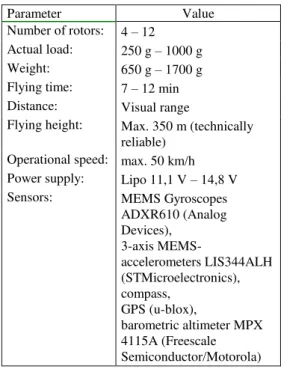
Tab. 1 gives an overview of the technical parameters of the systems available. Actually two MikroKopter systems (Fig. 1) are used for the investigations: an Oktokopter of the HS BO and a Hexakopter of the project partner Aerometrics (www.aerometrics.de).
Parameter Value
Number of rotors: 4 – 12 Actual load: 250 g – 1000 g Weight: 650 g – 1700 g Flying time: 7 – 12 min Distance: Visual range
Flying height: Max. 350 m (technically reliable)
Operational speed: max. 50 km/h Power supply: Lipo 11,1 V – 14,8 V
Sensors: MEMS Gyroscopes
ADXR610 (Analog Devices),
3-axis
MEMS-accelerometers LIS344ALH (STMicroelectronics), compass,
GPS (u-blox),
barometric altimeter MPX 4115A (Freescale Semiconductor/Motorola) Table 1. Technical parameters of the MikroKopter system
Figure 1. Hexa- and Oktokopter during flight
The configuration of both copters is almost similar, particularly concerning the components for navigation (Fig. 2).
Figure 2. Electronic components for autonomous flight In case of the Oktokopter eight brushless-controllers regulate the motor speed (climbing and falling). The Flight-control is in charge of interaction of all electronic components and integrates gyroscopes and acceleration indicators for the levelling of the platform as well as a barometric altimeter. The Navi-control enlarges the options concerning the automatic flight (position hold, coming home, approaching waypoints). An integrated GPS-sensor is responsible for the fixing of the actual position. An optional telemetry-module works at a frequency range of 868-870 MHz with an operation distance of some hundred meters. All relevant operating data of the copter are transferred to the ground control in realtime. At least the additional 5,8 GHz A/V-transmitter-system allows to broadcast the life image from the camera.
The camera used during the tests is a Ricoh GXR (resolution 3776 * 2832 pixel) with an 18mm lens. The camera together with the camera-platform have a total weight of about 750 gr. (Fig. 3)
Figure 3. Oktokopter with fixed Ricoh GXR camera system
3. INVESTIGATION OF POSITIONING SENSORS
In the following the generated data of the GPS-sensor and the barometric altimeter are going to be tested, as these components are responsible for the positioning of the copter during the flight.
GPS-Module Navi-Control
Flight-Control
Brushless-Controller
Telemetry-Module International Archives of the Photogrammetry, Remote Sensing and Spatial Information Sciences, Volume XXXVIII-1/C22, 2011
3.1 u-blox GPS receiver
The horizontal position informations are delivered by the u-blox LEA-6S GPS receiver (Fig. 4), (u-blox, 2011, Bäumker, 2009). The receiver has 50 channels (GPS-L1/CA-Code, GALILEO OS) and includes the SBAS-option (satellite based augmentation system) to acquire the correction signals of WAAS, EGNOS or MSAS. The signals of the two EGNOS (European Geostationary Navigation Overlay System) satellites Inmarsat AOR-E and IOR-W are available at Bochum and used to calculate a differential GPS position.
Unfortunately there was no information available during the tests concerning the internal signal processing of the receiver. Generally a configuration tool is provided by u-blox to check the receivers function and the data logging.
Figure 4. u-blox receivers as part of the GPS circuit board. Left: board surrounded by a protection shield to enhance GPS
signal
3.2 GPS Performance Evaluation
The reference system normally used in German photogrammetry is the ETRS89 system with its UTM-coordinates. All investigations take place in this system.
To check the performance of the GPS-sensor diverse test were carried out:
1. Long term measurements at a reference station (static) 2. Short term measurements at known ground control
points (static)
3. Short term measurements during flight over a known ground control point (dynamic)
4. Aerial flights with operating altitude of 50m and 100m (dynamic)
The integrated IMU is not a subject matter of the following testings, because it is not involved into the navigation process. Its only task within the system is to level the platform.
3.2.1 Long term measurements at a reference station (static)
A buildings roof, with an installed GPS reference station, had been used as location for a static test with the Oktokopter. The tests last several hours and should demonstrate the accuracy of the horizontal GPS positions in respect to the UTM coordinates of the reference point under static conditions.
The tests resulted in horizontal position differences of –0.7 m to 0.3 m in the east component and –1.1 m to – 1.7 m in the north component. This is the expected differential C/A-Code GPS accuracy using the code-corrections of the EGNOS satellites.
3.2.2 Short term measurements at known ground control points (static)
Further static tests were carried out by positioning the Oktokopter directly over several ground control points (accuracy < 1cm) of the test field (Fig. 5).
Figure 5. GPS measurements at ground control points The Oktokopter had been placed over the 28 ground control points for a minute to compare the horizontal positions with the given reference UTM coordinates. The recording of positions occurred with a data rate of 1 Hz, resulting in at least 60 measurements for each point. The standard deviations of the coordinates vary between 0.2 m to 5.0 m and the horizontal differences of the mean position to the reference coordinates achieve 0.6 m to 5.1 m. With the exception of 3 cases the differences are less than 2.8 m. These exceptions are probably caused by the lack of the EGNOS correction due to problems to receive the signals of AOR-E or IOR-W satellites at a low elevation angle of less than 30° in southern direction.
3.2.3 Short term measurements during flight over a known ground control point (dynamic)
A further test was performed under dynamic conditions by flying over a defined ground control point. The coordinates of a ground control point were set as a reference waypoint. The purpose was to investigate the overall position accuracy when flying over the ground control point. For these tests the GPS positions of the Navi-control were continuously recorded by the Navi-control itself. The recorded data show that the medium position coincides with the waypoint position better than 1 m. This offers the quality of the flight-control to maintain the vehicle over the waypoint.
Figure 6. Copter-Tracking with tachymeter Trimble S6 The results offer a typical oscillation caused by the controlling of the vehicle over the waypoint by the flight control. The amplitudes accomplish an amount of up to 6 m (Oktokopter) and only 1.5 m with the Hexakopter. Because the flight and weather conditions were nearly the same the differences are
caused by the PID-control loops of the motors. While the control loop of the Hexakopter shows an appropriate behavior the PID-values of the Oktokopter have to be further investigated and optimised. The PID (Proportional-Integral-Differential)-controllers have to consider the mass and bending of the copter, the delay of the motor controllers, the errors of the sensors as well as ambient disturbances (e.g. wind), (Unbehauen, 2008). 3.2.4 Aerial flights with operating altitude of 50m and 100m (dynamic)
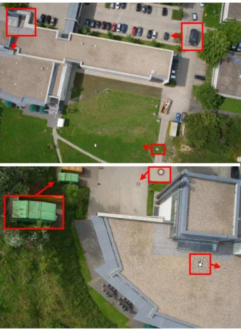
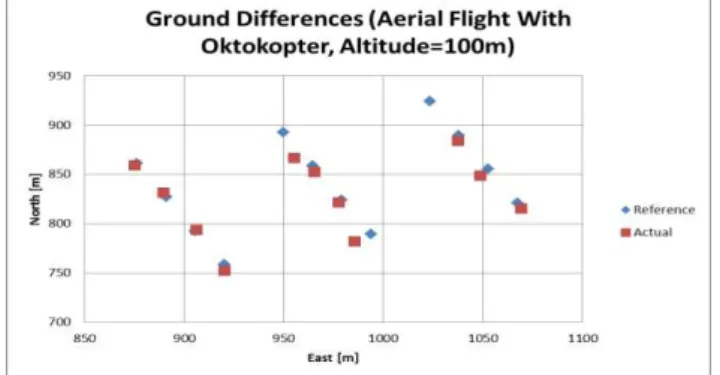
To determine the positioning quality (ground and elevation) during aerial flights some test flights with the copters had been carried out. An example of image acquisition is given in Fig. 7, which shows a partial area of the Bochum test field, shot from the Oktokopter at an altitude of 100m (camera: Ricoh GXR). To control the aerial flight the software „Mission Cockpit“ had been used (Walther, 2011). The data interchange is carried out between the ground control station and the onboard telemetry module, enhanced by the tracking antenna, following the copters flight path (Fig. 8). After launching the copter and reaching a planned elevation it is switched to autonomous flight mode. A snap distance has to be predefined. When reaching the snap distance a countdown (normally some seconds) starts and the image can be taken alternative automatically or manually. Some problems arise if the given limit cannot be reached because of oscillation effects of the vehicle. In this case the camera has to be triggered by the pilot. Fig. 9 shows the results referring to these tests.
Figure 7. Aerial images (camera: Ricoh GXR, f=18mm) Top: 1/870sec, F/5.6, ISO 200, altitude: 100m Bottom 1/1410sec, F/4.0, ISO200, altitude: 50m) International Archives of the Photogrammetry, Remote Sensing and Spatial Information Sciences, Volume XXXVIII-1/C22, 2011
Figure 8. Ground control with tracking antenna Over all some positions failed, which means no image had been taken or taken too late (manually). The quality of positioning varies with a mean deviation from 3 – 4 m, not considering some outlier of more than 10 m.
It seems to be necessary to optimize the automatic triggering process, as in some cases taking an image at a correct position is almost a fortune.
Figure 9. Comparison of reference and realised ground positions during aerial flight
3.3 Barometric Altimeter Capability Approval
The barometric height is derived by a static pressure sensor (Table 1) which is initialized with 0 m at the starting point. Based on the fact that the barometric pressure decreases 1.2kPa/100m (legal assumption between sea level and an altitude of 1500 m) the copter uses this effect for a relative height measurement. Thus the barometric height represents the height above ground and is used by the flight control.
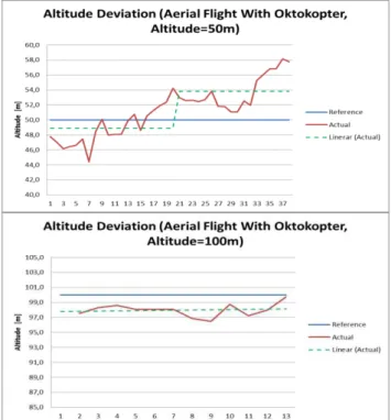
During the tests the altitude had been set manually by the altitude hold switch. Via telemetry the actual barometric height was sent to the ground control and monitored until the desired height had been reached. Activating the altitude hold switch resulted in an subsequent autonomous control of the determined height.
Figure 10. Comparison of reference and realised altitude during aerial flight
To independently verify the height further tests were carried out at waypoint 8. While hovering above the waypoint the copters were tracked by the tachymeter (Trimble S6). The barometric heights recorded by the copters were compared with the heights calculated from the measurements of the tachymeter. The results, concerning the Hexakopter, are shown in Figure 11. A systematic error of 9 m with deviations of 1 m (altimeter) and 0.3 m (tachymeter) can be observed. The results achieved with the Oktokopter offer a systematic error of –8 m and deviations of 1 m (altimeter) and 0.6 m (Trimble S6). This shows that the accuracy of the altitude hold feature can cause deviations up to 10 m of the predefined height. An improvement would be possible if the GPS height would be used additionally, in combination with the barometric height.
Figure 11. Comparison of the heights over waypoint 8
4. CONCLUSIONS
A first benchmark carried out with the MikroKopter UAV results in the especial ability to use the system for future photogrammetric applications (e.g. aerial triangulations and
other GIS-applications). With special focus on the navigation components, independently examined by an automatic tracking of the UAV with a tachymeter, the high potential of the integrated GPS could be shown. Further enhancements might be possible by integrating Real-Time-Kinematic (RTK)-GPS technology into the nagivation process.
The barometric sensor matches the expectations, but an improvement of the height measurement might be possible by also using GPS-data.
The comparison of the flight characteristics of the two test copters indicates that an adjustment of the PID control loops is worthwhile.
The images taken with the Ricoh digital camera in conjunction with the adopted camera-platform show high quality, but the triggering process has to be enhanced, as well as the disposable flying time.
5. REFERENCES
References from Journals:
Przybilla, H.-J. & Wester-Ebbinghaus, W., 1979. Bildflug mit ferngelenktem Kleinflugzeug. Bildmessung und Luftbildwesen.
Zeitschrift für Photogrammetrie und Fernerkundung.
HerbertWichman Verlag. Karlsruhe.
Wester-Ebbinghaus, W., 1980. Aerial Photography By Radio Controlled Model Helicopter. The Photogrammetric Record, Volume 10, Issue 55, pages 85–92
References from Books:
Unbehauen, H. 2008. Regelungstechnik I. 15. Auflage. Verlag Vieweg + Teubner. ISBN-10: 3834802301
References from Other Literature:
Bäumker, M., 2009: GALILEO4Firebrigades (G4FB) – Abschlussbericht, TIB Hannover.
Eisenbeiss, H., 2009. UAV Photogrammetry. Dissertation ETH Zürich. IPG Mitteilungen Nr. 105, ISSN 0252-9335
References from websites:
MikroKopter, 2011. Website for MikroKopter do-it-yourself construction. http://www.mikrokopter.de (accessed 20 July 2011)
Walther, R., 2011. Mission Cockpit (software and manual). http://svn.mikrokopter.de/listing.php?repname=Projects&path= %2FMissionCockpit%2Ftags%2FV0.6.0%2F&#A8e147b51cb0 fcd3aa5c3b1b6a54ff671 (accessed 20 July 2011)
u-blox, 2011. u-blox 6 receiver description including protocol specification. http://www.u-blox.com (accessed 20 July 2011)
6. ACKNOWLEDGEMENTS
Thanks a lot to all collegiate volunteers of the lab of photogrammetry for supporting the field work. A special thanks to Magdalena Dannenberg for her really great commitment in configuring and measuring the test field and Alexander Zurhorst for inspiring discussions concerning MikroKopters, as well as the mutual test flights.
Thanks to the chair of Bochum University of Applied Sciences for financial support of the project.