RBCDH
Licence Creative Commom
CC BY
Noncircular chainrings and pedal to crank
interface in cycling: a literature review
Sistemas de pedivela não-circulares e interfaces
pedal-pedivela no ciclismo: uma revisão da literatura
Rodrigo R. Bini1,2
Frederico Dagnese3
Abstract– Noncircular chainrings and novel pedal to crank interfaces have been designed to optimize variables related to cycling performance (e.g. peak crank torque and eiciency), with conlicting results in terms of performance. herefore, the aim of the present article was to review the theoretical background of noncircular chainrings and novel pedal to crank interfaces and their efects on biomechanical, physiological and performance vari-ables. Reducing internal work, crank peak torque, and time spent at the top and bottom dead centres (12 o’clock and 6 o’clock positions, respectively) were among the various targets of noncircular chainrings and novel pedal to crank interface design. Changes in joint kinematics without efects on muscle activation were observed when cyclists were assessed using noncircular chainrings and novel pedal to crank interfaces. Conlicting results for economy/eiciency explain the unclear efects of noncircular chainrings on cycling performance and the positive efects of some novel pedal to crank interfaces on cycling economy/eiciency.
Key words: Eiciency; Electromyography; Kinematics; Performance.
Resumo – Sistemas de coroas não circulares e novas interfaces entre o pedal e o pedivela vem sendo propostas com o objetivo de otimizar variaveis relacionadas com o desempenho no ciclismo (e.g. pico de torque e eiciência) com resultados conlitantes acerca do desempenho. Nesta perspectiva, o objetivo desta revisão foi abordar aspectos teóricos do uso de sistemas de pedivela não circulares e novas interfaces entre o pedal e o pedivela e seus efeitos em variáveis biomecânicas, isiológicas e do desempenho. A redução do trabalho interno, pico de torque no pedivela e tempo decorrido nos pontos mortos (posições de 12 horas e 6 horas) estiveram entre as variáveis utilizadas para otimizar o desenho de sistemas de pedivela não circulares e novas interfaces entre o pedal e o pedivela. Alterações na cinemática foram observadas sem mudanças na ativação dos músculos dos membros inferiores de ciclistas utlizando sis-temas de pesdivela não-circulares e novas interfaces entre o pedal e o pedivela. Resultados conlitantes foram observados na economia/eiciência indicando beneicios pouco claros do uso de sistemas de pedivela não circulares e resultados positivos do uso de novas interfaces entre o pedal e o pedivela na economia/eiciência.
1 Auckland University of Techno-logy. Sport Performance Research Institute. Auckland, AKL, New Zealand.
2 Ministry of Education. Capes Foundation. Brasília, DF. Brazil
3 Universidade Federal do Rio Grande do Sul. Laboratório de Pes-quisa do Exercício. Porto Alegre, RS. Brazil
INTRODUCTION
he progress in training programs and applied technology enabled coaches to improve training monitoring and performance of athletes throughout the
years1. In cycling, changes in the design of bicycles aimed to reduce rolling
resistance and internal work (mechanical work to move the legs) towards
greater travelling speed2. Aerodynamic force is the major resistive force in
cycling, so new designs for wheels3, shoes4, frames5, and handlebars6 have
been presented with the aim of reducing drag force, leading to improved performance. Assuming that lower energy expenditure for cycling at target workload (i.e. greater economy/eiciency) will be related to better perfor-mance, declines in energy expenditure may be observed when external and/or internal work decreases (i.e. energy spent to overcome cycling external forces and energy spent to move the leg without external resistance, respectively). On the other hand, the possibility to increase power output for the same energy expenditure has helped researchers to look for better
economy/ef-iciency markers (i.e. oxygen uptake or heart rate)7. Because power output
depends on the moment arm of the crank and the tangential force applied on the crank (efective force), for a hypothetical constant force applica-tion, a larger moment arm should increase crank torque. However, due to mechanical and anatomical constraints, the efective force is hardly ever constant, which suggests that the moment arm of the crank would change throughout crank revolution to maximize crank torque. With this
in mind, changes in crank length8,9, pedal to crank interface10,11, and in the
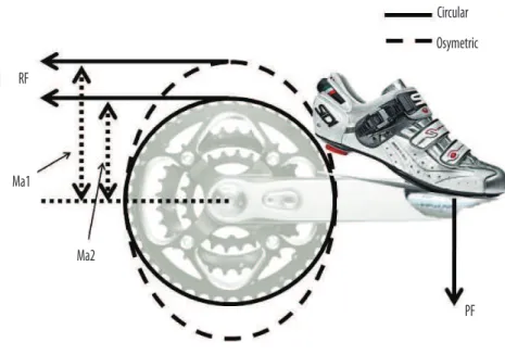
regular proile of the chainring have been devised (Figure 1)12-14. Even with
strong theoretical support, some of these novel devices uncertainly afect
biomechanical, physiological or performance variables15-18.
Diferent designs of noncircular chainrings and pedal to crank inter-faces have been presented in the literature and have afected physiological and biomechanical variables related to performance in diferent ways. Better insight needs to be provided for cyclists and coaches when choosing a noncircular chainring system or a particular pedal to crank interface.
herefore, the aim of the present article was to review the theoretical background of noncircular chainrings and novel pedal to crank interfaces and their efects on biomechanical, physiological and performance variables.
METHODS
Academic databases (MEDLINE, SCOPUS, ISI Web of Knowledge, EBSCO, and Google Scholar) were searched for peer-review journals, books, theses, and conference proceedings published since 1960 with the keywords: ‘pedal to crank interface’, ‘chainring’, and ‘noncircular’. Within the initial 2,165 references, the keyword ‘bicycle’ was used to reine the search. Twenty-nine articles were then analyzed through their abstract. hose that focused on presenting theoretical design or experimentally assessed noncircular chairing systems or pedal to crank interfaces were retrieved for the analysis of the full article version. References used by thirteen articles selected ater full version analysis were also analysed by article title, which was followed by abstract and full article analysis. A total of 39 references were selected for this review, including 37 journal articles, one book, and one web page. We opted to include a large range of study designs (i.e. cross-sectional to computer simulations) to expand the discussion from the theoretical to the practical beneits of using noncircular chanrings and/or diferent pedal to crank interfaces.
DISCUSSION
Reducing internal work, crank peak torque, and time spent at the top and bottom dead centres (12 o’clock and 6 o’clock positions, respectively) were among the vari-ous targets of noncircular chainring and novel pedal to crank interface design. Changes in joint kinematics without efects on muscle activation were observed when cyclists were assessed using noncircular chainrings and novel pedal to crank interfaces. Conlicting results in cycling economy/eiciency and performance were observed using most of the noncircular chainrings. Novel designs for pedal to crank interfaces have provided increments in cycling economy/eiciency.
Theoretical background for changing crank length or pedal to crank
interface, or using noncircular chainring
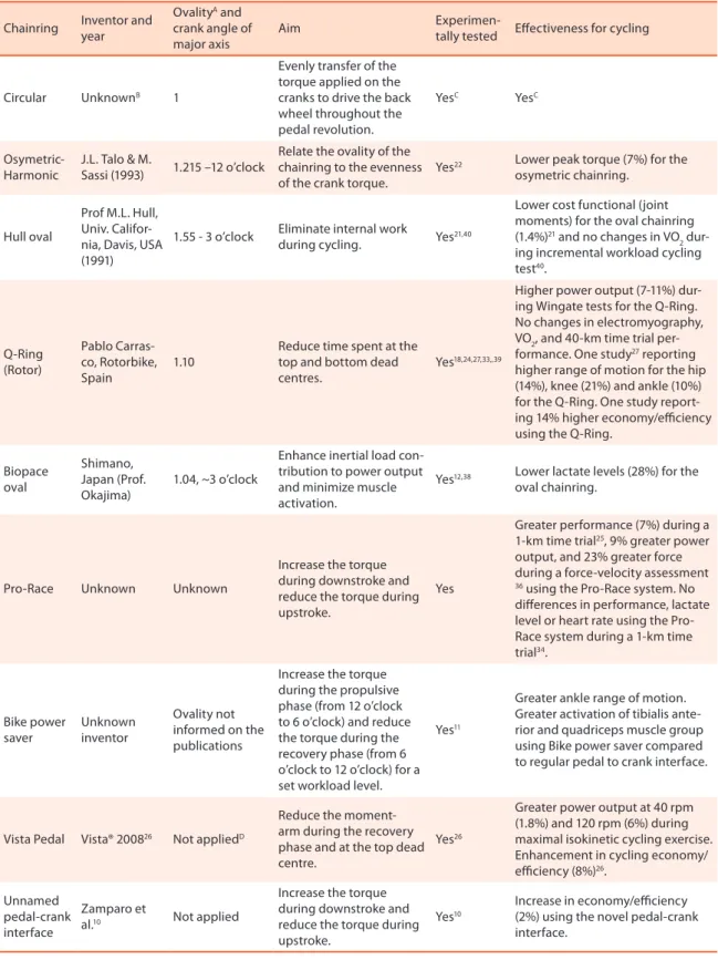
Noncircular chainring systems and devices aiming to change pedal to crank interface introduced throughout the years are presented in Table 1. When introducing the diferent chainring and pedal to crank interface systems, the deinition of the crank angle of the major axis (greater moment arm of the chain to the bottom bracket – i.e. resistive force) was based on the position of the crank at 3 o’clock, following the assumption that the peak
Table 1. Summary of the noncircular chainring systems and pedal-crank interfaces presented throughout the years, including inventor and year, ovality, crank angle of the major axis, aim of the design, and if the referred system has been experimentally tested. All results are based on a similar exercise condition using a circular and a noncircular chainring system.
Chainring Inventor and year
OvalityA and crank angle of major axis
Aim
Experimen-tally tested Efectiveness for cycling
Circular UnknownB 1
Evenly transfer of the torque applied on the cranks to drive the back wheel throughout the pedal revolution.
YesC YesC
Osymetric-Harmonic
J.L. Talo & M.
Sassi (1993) 1.215 –12 o’clock
Relate the ovality of the chainring to the evenness of the crank torque.
Yes22 Lower peak torque (7%) for the osymetric chainring.
Hull oval
Prof M.L. Hull, Univ. Califor-nia, Davis, USA (1991)
1.55 - 3 o’clock Eliminate internal work
during cycling. Yes
21,40
Lower cost functional (joint moments) for the oval chainring (1.4%)21 and no changes in VO
2 dur-ing incremental workload cycldur-ing test40.
Q-Ring (Rotor) Pablo Carras-co, Rotorbike, Spain 1.10
Reduce time spent at the top and bottom dead centres.
Yes18,24,27,33,,39
Higher power output (7-11%) dur-ing Wdur-ingate tests for the Q-Rdur-ing. No changes in electromyography, VO2, and 40-km time trial per-formance. One study27 reporting higher range of motion for the hip (14%), knee (21%) and ankle (10%) for the Q-Ring. One study report-ing 14% higher economy/eiciency using the Q-Ring.
Biopace oval
Shimano, Japan (Prof. Okajima)
1.04, ~3 o’clock
Enhance inertial load con-tribution to power output and minimize muscle activation.
Yes12,38 Lower lactate levels (28%) for the oval chainring.
Pro-Race Unknown Unknown
Increase the torque during downstroke and reduce the torque during upstroke.
Yes
Greater performance (7%) during a 1-km time trial25, 9% greater power output, and 23% greater force during a force-velocity assessment 36 using the Pro-Race system. No diferences in performance, lactate level or heart rate using the Pro-Race system during a 1-km time trial34.
Bike power saver
Unknown inventor
Ovality not informed on the publications
Increase the torque during the propulsive phase (from 12 o’clock to 6 o’clock) and reduce the torque during the recovery phase (from 6 o’clock to 12 o’clock) for a set workload level.
Yes11
Greater ankle range of motion. Greater activation of tibialis ante-rior and quadriceps muscle group using Bike power saver compared to regular pedal to crank interface.
Vista Pedal Vista® 200826 Not appliedD
Reduce the moment-arm during the recovery phase and at the top dead centre.
Yes26
Greater power output at 40 rpm (1.8%) and 120 rpm (6%) during maximal isokinetic cycling exercise. Enhancement in cycling economy/ eiciency (8%)26.
Unnamed pedal-crank interface
Zamparo et
al.10 Not applied
Increase the torque during downstroke and reduce the torque during upstroke.
Yes10
Increase in economy/eiciency (2%) using the novel pedal-crank interface.
ARatio between the major and the minor axis; BUnknown origin. Possible inclusion in the bicycle drive system in 18602.
CUsed as a reference system for comparison with the noncircular chainrings.
We can observe that the various noncircular chainring designs and systems to change pedal to crank interface had diferent target variables for optimization (e.g. crank torque) based on changing the ratio between the major and the minor axis of the chainring or the distance between pedal and bottom bracket (e.g. pedal to crank interface systems). he crank angle of the major axis may also afect the torque produced by the resistive force, as shown in Figures 1 and 2. he resistive force is a sum of the drag, bearing, rolling and inertial forces applied to the bicycle and transferred to the crank set via the gears and chain.
PF Circular
Osymetric
Ma RF
Figure 2. Illustration of the Biopace noncircular chainring devised to increase the moment arm close to the 3 o’clock position. Moment arm of the noncircular chainring (Ma), resistive force (RF) and pedal force (PF).
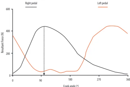
In Figure 2, we can observe that the major axes of the chainring are close to the 3 o’clock and 9 o’clock positions, diferent from the design pre-sented in Figure 1, in which the major axes are close to the 12 o’clock and 6 o’clock positions for the same position of the crank. Following a pedal force proile as shown in Figure 3, when the maximal pushing force on the pedal is applied close to 90° of the crank angle (3 o’clock crank position), both noncircular chainrings shown in Figure 1 and 2 may present diferent results. he greater moment arm of the noncircular chainring of Figure 1 may require larger pedal force application to sustain a similar crank torque, compared to the noncircular chainring presented in Figure 2.
he efectiveness of each chainring system could be theoretically as-sessed by whether the major axes might properly increase the moment arm of the resistive force when the pedal is close to the crank angle of peak pedal force (3 o’clock). herefore, increasing the moment arm of the resistive force may increase the torque produced by the resistive force and require greater peak pedal force application for a set workload level.
Using a circular chainring, the instantaneous velocity of the crank varies
±22% for an average pedalling cadence of 90 rpm20, which has been related
the areas of the pedal revolution of lower velocity (e.g. 3 o’clock position) resulted in smoother instantaneous velocity of the crank and lower internal
work21. Based on a similar perspective, some noncircular chainrings were
devised to focus on increasing the evenness of crank torque, which resulted
in lower peak torque22 (similar to models as per shown in Figure 1). Other
chainrings had focus on reducing the time spent at the top and bottom dead centres (12 o’clock and 6 o’clock positions, respectively) (e.g. Rotor system)
because little force is applied on the pedal in these areas of pedal revolution23.
he Rotor system is a circular chainring including a decoupled mechanism that detaches the cranks at the 12 o’clock and 6 o’clock positions by mov-ing the drivmov-ing crank forward in relation to the opposite crank. herefore, some systems were developed to reduce the axes at the top and bottom dead
centres21 and others to mechanically decoupled the cranks in these areas
of pedal revolution24. Another system was developed to increase the axis
at the 3 o’clock position and reduce the axis at the 9 o’clock position (i.e.
Pro-Race) 25. his last system would reduce the retarding torque produced
by the force applied on the pedal during the recovery phase (from 6 o’clock to 12 o’clock positions of the crank), but there is no supporting data for this hypothesis. Because the target optimization variable of these systems was diferent (e.g. internal work or lower crank torque), it is not clear how they can afect biomechanical, physiological and performance markers. It is unclear if the noncircular chainring should be designed to increase the moment arm of the resistive force at the 12 o’clock position of the crank to improve the torque of the resistive force (e.g. model of Figure 1) or if it should reduce the moment arm of the resistive force at the 3 o’clock posi-tion to reduce internal work and peak crank torque (e.g. model of Figure 2).
Resultant F
or
ce (N)
Crank angle (º) 0
0 200 400 600
Right pedal Left pedal
90 180 270 360
Figure 3. Resultant force applied on the right and left pedals as a function of the crank angle. Unpublished data of one competitive cyclist riding a 4-km time trial on a stationary cycle ergometer using circular chainrings.
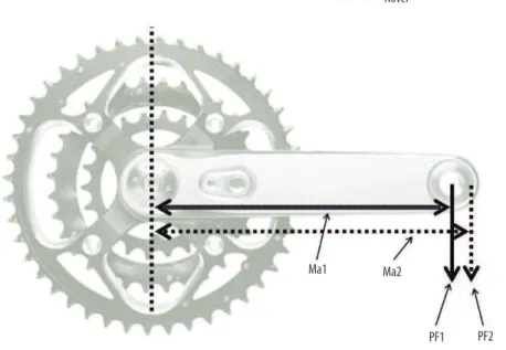
length at the 9 o’clock position of the crank may enhance power output. his was the aim of the novel pedal to crank interface devised by Zamparo
et al.10 and by Koninckx et al.26 and of the system assessed by Shan11, which
are illustrated in Figure 4.
Figure 4. Illustration of a shorter (Ma1) and longer (Ma2) crank moment arm due to a diferent pedal to crank interface (PF2) compared to the standard pedal to crank interface (PF1).
Economy/eiciency (ratio between mechanical work and energy
ex-penditure) improved using the systems developed by Zamparo et al.10 (2%)
and by Koninckx et al.26 (8%), which suggests a positive efect of reducing
crank length at the 9 o’clock position of the crank potentially due to reduced resistive torque on the crank.
Changes in chainring characteristics were varied in the developed models, with focus ranging from the change in crank length of the 3 o’clock
and 9’clock positions25 to changes in moment arms of the resistive force.
It is likely that noncircular chainring models should reduce the moment arm of the resistive force at the 3 o’clock position to reduce internal work and peak crank torque (e.g. model of Figure 2).
Efects of changing pedal to crank interface or using noncircular chainring
on biomechanical variables
From the theoretical design of the noncircular chainring illustrated in Fig-ure 1, the greater axis at the 12 o’clock position of the crank may enhance the moment arm of the resistive force when the pedal is at the 3 o’clock posi-tion, which will require a greater pedal force application for a set workload level. he great moment arm may be also related to lower instantaneous
velocity of the pedal at this position of the crank20, which may afect joint
et al.10, increases the moment arm of pedal force when the pedal is at the 3
o’clock position. On the other hand, Shan11 observed that the “Bike saver”
system resulted in a shorter crank length between the 12 o’clock and the 3 o’clock positions of the crank, in contrary to the purpose of the manu-facturer. herefore, the design of the system must account for reducing crank length at the 9 o’clock position of the crank and/or increase crank length at the 3 o’clock position of the crank. Another option would be to reduce the chainring axes at the 12 o’clock and 6 o’clock position when the crank is at the 3 o’clock position, as per shown in Figure 2. hese changes may result in reduced resistive crank torque at the 9 o’clock position of the crank, smaller luctuations in crank angular velocity, and reduced resistive force to the cyclists.
Some studies focused on the efects on joint kinematics using noncir-cular chainrings or diferent pedal to crank interfaces. When changing
pedal to crank interface, Shan11 observed greater range of motion for the
ankle joint, compared to the use of normal pedal to crank interface. he shorter crank length between the 12 o’clock and the 3 o’clock positions of the crank may explain the greater range of motion observed at the ankle joint.
Greater range of motion for the ankle (10%), knee (21%) and hip (14%)
was found for ive cyclists riding at 300 W when using the Rotor system27,
which intended to reduce the time spent at the 12 o’clock position of the crank. Another study observed 30% greater range of motion for the ankle and 5% greater range of motion for the knee joint among 15 professional cyclists riding at a workload 10% lower than the anaerobic threshold using
the Rotor system28. hese results have been linked to the possible increase
in efective crank arm length using the Rotor system27, without further
information on the mechanism related to this increase. Hip, knee and an-kle angles did not difer when non-athletes cycled at steady state workload using a noncircular chainring that had the major chainring axis at the 12
o’clock position (similar to Figure 1) compared to a circular chainring29.
Only Shan11 assessed muscle activation during pedalling using a novel
pedal to crank interface. Higher activation of quadriceps muscle group and tibialis anterior was observed. he explanation for this result may be related to the shorter crank length between the 12 o’clock and the 3 o’clock positions and the greater range of motion of the ankle joint when using this system compared to a standard pedal to crank interface. Only one study measured muscle activation of the lower limb of cyclists using a Rotor
system noncircular chainring30 without signiicant diferences compared to
the circular chainring system. No study was found with measurements of muscle activation of subjects using other designs of noncircular chainring or pedal to crank interfaces.
Generally, the studies describing noncircular chainrings aimed to de-termine an optimal major to minor axis with focus on reducing joint
mo-ments14,21 or crank torque31 for a set workload level or increasing maximal
power output for a set distance or time of exercise32. One study reported no
aim-ing to increase the axis at the 12 o’clock position on joint moments (similar
to Figure 1)14. Another study presented ~12% lower peak crank torque for the
noncircular chainring (epicyclical) aiming to enhance the axis between the 12 o’clock and the 3 o’clock positions of the crank compared to the circular
chainring31 (similar to Figure 1). On the other hand, the increase in the
axis of the chainring at 3 o’clock position of the crank (similar to Figure 2)
have lead to lower average joint moment (1.4%)21. Malfait et al.32 compared
various designs of noncircular chainrings through computer simulations of constant workload or constant joint power. he authors reported that only the Hull oval system, which aimed to increase the axis at the 3 o’clock position of the crank (similar to Figure 2), resulted in improvements in power output when the major axis was changed clockwise by 17.5° from its original design (4.5%). When changing the position of the crank of the
major axis of the chainring, Malfait et al.32 observed that most systems have
improved power output (1-13%). Changes in joint power were varied, with some systems improving knee and hip joint extensor power while others afected only the lexor power of these joints. However, it is not clear how in-dividual changes in joint power may lead to improvements in performance. here is a gap of studies with focus on assessing biomechanical variables (e.g. pedal forces and joint kinetics) of noncircular chainrings and pedal to crank interfaces. he validity of the adapted design of the chainrings
devised by Malfait et al.32 could give substantial evidence for the beneits
of using these systems in terms of cycling biomechanics. At the moment, noncircular chainrings that aim to increase the axis of the chainring at the 3 o’clock position of the crank (similar to Figure 2) may provide more beneits compared to the ones that increase the axis of the chainring at the
12 o’clock position (similar to Figure 1). Pedal to crank interface systems10,26
have not been assessed in terms of biomechanical variables. Another pedal to crank interface system resulted in greater ankle range of motion and
greater activation of tibialis anterior and quadriceps muscle group11, which
precludes its application for cycling training.
Efects of changing pedal to crank interface or using noncircular chainring
on physiological variables
Based on the expected reduction in internal work using most noncircular chainrings systems, overall energy expenditure would be expected to decline for a set level of workload. In this regard, most studies looked at physiological markers related to endurance performance when assessing
noncircular chainrings in cycling12,18,33. In a similar direction, the novel
pedal to crank interfaces presented by Zamparo et al.10 and Shan11 were
assessed by measuring oxygen uptake at constant workload tests to infer on cycling economy/eiciency, with 2% greater economy/eiciency for the
pedal to crank interfaces presented by Zamparo et al.10. he Biopace
chain-ring (greater axis of the chainchain-ring at the 3 o’clock position – Figure 2) was
tested without substantial changes in oxygen uptake12 compared to circular
the 3 o’clock position and reduce it at the 9 o’clock position, did not improve
maximal power output or VO2max during incremental maximal tests34. he
“Harmonic” system, which also aimed to increase the axis of the chainring close to the 3 o’clock position (78° of crank angle, similar to Figure 2), was analyzed in terms of economy/eiciency in thirteen competitive cyclists at diferent workload levels without signiicant diferences compared to
circular chainrings16. On the other hand, conlicting results were found for
the Rotor system. Greater economy/eiciency (14%) was observed in eight
non-cyclists riding at 60% and 90% of VO2max24, which difered from the
trivial changes in VO2max and economy/eiciency for ten cyclists during a
constant workload test at 80% of the peak power output18 and for another
group of iteen cyclists performing a similar cycling exercise28.
Despite diferent designs, similarities in physiological markers between noncircular and circular chainrings have been related to the similar demand imposed by the noncircular chainrings to the musculoskeletal system.
Only Zamparo et al.10 and Koninckx et al.26 showed increments in cycling
economy/eiciency using a custom-made pedal to crank interface. Conlict-ing results were found for most of the noncircular chainrConlict-ings. Kautz and
Hull35 suggested that muscle force-velocity relationship is not usually taken
into account on the design of the noncircular chainrings, which may explain why physiological variables are not afected using noncircular chainrings.
Efects of changing pedal to crank interface or using noncircular chainring
on cycling performance
Apart from their inluence in economy/eiciency, the use of noncircular chainrings or diferent pedal to crank interface should lead to improve-ments in cycling performance. Endurance performance has been measured
through elapsed time25 or average power output during time trial tests34.
Greater average power output in an isokinetic maximal cycling exercise was observed using the novel Vista® pedals for cyclists pedalling from 40
rpm (1.8%) to 120 rpm (6%)26. Greater performance during a 1-km time
trial in the laboratory25 and no improvements during a similar time trial
on the track34 were found using the Pro-race system (greater axis of the
chainring at 3 o’clock position and smaller axis at the 9 o’clock position). Potential variability in the characteristics of the cyclists (e.g. maximal lower limb strength) during the 1-km time trial on the track was observed by the authors to afect the diferences between chainring systems. his system was also efective during a force-velocity test in a cycle ergometer, with 9% greater power output and 23% greater force applied on the cranks by ten
non-cyclists36. During a 40-km time trial, twelve competitive cyclists did
not improve their performance using the Rotor system15, as per indings
of Dagnese et al.30 for a time to exhaustion trial with seven competitive
cyclists. Diferently, greater average power output (8%) and peak power
output (9%) were found during a Wingate test using the Rotor system28.
During an incremental test to exhaustion, competitive cyclists did not
Future research
In theory, noncircular chainrings have the potential to enhance cycling performance due to smoother luctuations in crank angular velocity and
reductions in internal work14,21. However, future research may look at the
design of the noncircular chainring with the purpose of optimizing the section of crank revolution of the major axis of the chainring. Simulation studies may indicate in what sectors of crank revolution greater/smaller chainring axis should be used. Characteristics of the musculoskeletal system (e.g. force-length and force-velocity relationships) should be taken into account, because they determine optimal joint angles for muscle power production. Experimental studies with cyclists may indicate whether or not the noncircular chainrings tested in simulation models are efective to improve performance. A comparison across diferent pedalling technique styles may add to the existing simulation models that are limited to a
stand-ard pedal force application proile32. At the moment, noncircular chainrings
with focus on increasing the axis of the chainring at the 3 o’clock position and reducing the axis of the chainring at the 9 o’clock position (similar to
Figure 2) may have provided better results25,34,36.
CONCLUSIONS
he unclear efects of using most commercial noncircular chainrings in biomechanical and physiological variables preclude their efectiveness to enhance cycling performance. Diferent designs of noncircular chainrings limit the rationality of most of these systems for cycling performance, once they focus on optimizing diferent variables that may not lead to optimal performance. Custom-made systems focused on increasing crank moment arm or chainring axis at the 3 o’clock position and reducing the crank mo-ment arm or axis at the 9 o’clock position have provided improvemo-ments in cycling economy/eiciency and performance.
Acknowledgments
he irst author acknowledges Capes (Brazil) for his scholarship. he sec-ondary author acknowledges CNPq (Brazil) for the scholarship.
REFERENCES
1. Neptune RR, McGowan CP, Fiandt JM. he inluence of muscle physiology and
advanced technology on sports performance. Annu Rev Biomed Eng 2009;11:81-107.
2. Minetti AE, Pinkerton J, Zamparo P. From bipedalism to bicyclism: Evolution in en-ergetics and biomechanics of historic bicycles. Proc Biol Sci 2001;268(1474):1351-60.
3. Tew GS, Sayers AT. Aerodynamics of yawed racing cycle wheels. J Wind Eng Ind
Aerodyn 1999;82(1):209-22.
4. Gibertini G, Grassi D, Macchi C, de Bortoli G. Cycling shoe aerodynamics. Sports
Eng 2010;12(3):155-61.
5. Zdravkovich MM. Aerodynamics of bicycle wheel and frame. J Wind Eng Ind
6. Wurnitschb W, Siebert M, Litzenberger S, Sabo A. Development of an individually customizable integral carbon aerobar based on sEMG measurements of the upper limbs. Proc Eng 2010;2:2631-5.
7. Ettema G, Loras HW. Efficiency in cycling: A review. Eur J Appl Physiol
2009;106(1):1-14.
8. MacDermid PW, Edwards AM. Inluence of crank length on cycle ergometry
performance of well-trained female cross-country mountain bike athletes. Eur J Appl Physiol 2010;108(1):177-82.
9. Yoshihuku Y, Herzog W. Maximal muscle power output in cycling: A modelling
approach. J Sports Sci 1996;14(2):139-57.
10. Zamparo P, Minetti AE, Di Prampero PE. Mechanical eiciency of cycling with a
new developed pedal-crank. J Biomech 2002;35(10):1387-98.
11. Shan G. Biomechanical evaluation of bike power saver. Appl Ergon 2008;39(1):37-45.
12. Hull ML, Williams M, Williams K, Kautz S. Physiological response to cycling with both circular and noncircular chainrings. Med Sci Sports Exerc 1992;24(10):1114-22.
13. Cullen LK, Andrew K, Lair KR, Widger MJ, Timson BF. Eiciency of trained
cy-clists using circular and noncircular chainrings. Int J Sports Med 1992;13(3):264-9.
14. Han RPS, homlinson MA, Tu YS. Kinematics and kinetics of a non-circular bicycle
drive system. Mechan Mach heory 1991;26(4):375-88.
15. Jobson SA, Hopker J, Galbraith A, Coleman DA, Nevill AM. Efect of the Rotor
crank system on cycling performance. J Sports Sci Med 2009;8(3):463-7.
16. Ratel S, Poujade B, Duche P, Bedu M. Bioenergetic data comparison observed
during muscular exercise on bicycles equipped with ‘harmonic’ or circular chain rings. Sci Sports 1998;13(6):287-9.
17. Belen L, Habrard M, Micallef JP, Perrey S, Le Gallais D. Cycling performance
and mechanical variables using a new prototype chainring. Eur J Appl Physiol 2007;101(6):721-6.
18. Lucia A, Balmer J, Davison RCR, Perez M, Santalla A, Smith PM. Efects of the
Rotor pedalling system on the performance of trained cyclists during incremental and constant-load cycle-ergometer tests. Int J Sports Med 2004;25(7):479-85.
19. Coyle EF, Feltner ME, Kautz SA, Hamilton MT, Montain SJ, Baylor AM, et al.
Physiological and biomechanical factors associated with elite endurance cycling performance. Med Sci Sports Exerc 1991;23(1):93-107.
20. Hull ML, Kautz S, Beard A. An angular velocity proile in cycling derived from
mechanical energy analysis. J Biomech 1991;24(7):577-86.
21. Kautz SA. A comparison of muscular mechanical energy expenditure and internal
work in cycling. J Biomech 1994;27(12):1459-67.
22. Horvais N, Samozino P, Zameziati K, Hautier C, Hintzy F. Efects of a non circular chainring on muscular, mechanical and physiological parameters during cycle ergometer tests. Isokin Exerc Sci 2007;15(4):271-9.
23. Dorel S, Drouet JM, Couturier A, Champoux Y, Hug F. Changes of pedaling
technique and muscle coordination during an exhaustive exercise. Med Sci Sports Exerc 2009;41(6):1277-86.
24. Santalla A, Manzano JM, Perez M, Lucia A. A new pedaling design: he Rotor -
Ef-fects on cycling performance. Med Sci Sports Exerc 2002;34(11):1854-8.
25. Hue O, Galy O, Hertogh C, Casties JF, Prefaut C. Enhancing cycling performance
using an eccentric chainring. Med Sci Sports Exerc 2001;33(6):1006-10.
26. Koninckx E, van Leemputte M, Hespel P. Efect of a novel pedal design on
maxi-mal power output and mechanical eiciency in well-trained cyclists. J Sports Sci 2008;26(10):1015-23.
27. Carpes FP, Dagnese F, Mota CB, Stefanyshyn DJ. Cycling with noncircular
chain-ring system changes the three-dimensional kinematics of the lower limbs. Sports Biomech 2009;8(4):275-83.
28. Garcia-Lopez J, Rodriguez-Marroyo JA, Avila-Ordas MC, Villa-Vicente JG.
Address for Correspondence
Rodrigo Rico Bini Laboratório de Ensaios em Biomecânica
Instituto Brasileiro de Tecnologia do Couro, Calçado e Artefatos - Ibtec Rua Araxá, 750 - Bairro Ideal Novo Hamburgo - RS 93334-000, Brasil
Email: [email protected]
29. Bisi MC, Stagni R, Gnudi G, Cappello A. Non-circular chain ring allows a reduction of joint loading in cycling. J Mech Med Biol 2010;10(1):113-22.
30. Dagnese F, Carpes FP, Martins EDA, Stefanyshyn D, Mota CB. Efects of a
non-circular chainring system on muscle activation during cycling. J Electromyogr Kinesiol 2011;21(1):13-7.
31. Mundo D. Geometric design of a planetary gear train with non-circular gears.
Mechan Mach heory 2006;41(4):456-72.
32. Malfait L, Storme G, Derdeyn M. Comparative biomechanical study of circular and
non-circular chainrings for endurance cycling at constant speed. 2010 [updated 2010; cited 2010 28th August]; Available from: http://www.noncircularchainring.be/.
33. Rodriguez-Marroyo JA, Garcia-Lopez J, Chamari K, Cardova A, Hue O, Villa JG.
he rotor pedaling system improves anaerobic but not aerobic cycling performance in professional cyclists. Eur J Appl Physiol 2009;106(1):87-94.
34. Hue O, Chamari K, Damiani M, Blonc S, Hertogh C. he use of an eccentric
chain-ring duchain-ring an outdoor 1 km all-out cycling test. J Sci Med Sport 2007;10(3):180-6.
35. Kautz SA, Hull ML. Dynamic optimization analysis for equipment setup problems
in endurance cycling. J Biomech 1995;28(11):1391-401.
36. Hue O, Racinais S, Chamari K, Damiani M, Hertogh C, Blonc S. Does an eccentric
chainring improve conventional parameters of neuromuscular power? J Sci Med Sport 2008;11(3):264-70.
37. Rankin JW, Neptune RR. A theoretical analysis of an optimal chainring shape to
maximize crank power during isokinetic pedaling. J Biomech 2008;41(7):1494-502.
38. Hansen EA, Jensen K, Hallen J, Rasmussen J, Pedersen PK. Efect of chain wheel
shape on crank torque, freely chosen pedal rate, and physiological responses during submaximal cycling. J Physiol Anthropol 2009;28(6):261-7.
39. Peifer JJ, Abbiss CR. he inluence of elliptical chainrings on 10 km cycling time trial performance. Int J Sports Physiol Perf 2010;5(4):459-68.
40. Ratel S, Duché P, Hautier CA, Williams CA, Bedu M. Physiological responses