Advances in Mechanical Engineering 2015, Vol. 7(7) 1–13
ÓThe Author(s) 2015 DOI: 10.1177/1687814015594558 aime.sagepub.com
Investigation of heat transfer
enhancement inside developing
gravity-driven films along a vertical
permeable plate subject to nonuniform
suction
Abdul-Rahim A. Khaled
Abstract
Flow and heat transfer through the boundary layers of a falling liquid film on a vertical permeable plate subject to nonuni-form suction flow are analyzed in this work. The continuity, momentum, and energy equations are transnonuni-formed to nonsi-milar equations and solved using a validated implicit and iterative finite difference method. Increases in the Froude number, Galilei number, and the dimensionless average suction velocity are found to increase the skin friction coefficient, the Nusselt number, and the heat transfer enhancement ratios. These enhancement ratios are noticed to increase at the plate exit as the suction velocity power-law index increases. The Froude number for uniform suction case required to attain the same enhancement ratios due to nonuniform distribution of this suction flow is found to increase as the Galilei number, average suction velocity, and power-law index increase. It is found that the upper most values of the enhancement factors in heat transfer and Froude number arem+1folds when the suction power-law index is equal to m. This work demonstrated that significant heat transfer enhancement inside developing gravity-driven liquid films is attainable when properly distributing the suction velocity along the plate.
Keywords
Boundary layers, convective heat transfer, fluid mechanics, heat and mass transfer, computational fluid dynamics
Date received: 11 February 2015; accepted: 11 June 2015
Academic Editor: Gongnan Xie
Introduction
The transport phenomena associated with liquid falling films (gravity-driven liquid films) along solid surfaces are vital to many engineering applications. For exam-ple, liquid falling films are used in air conditioning applications where that liquid is a salt solution known as liquid desiccant. This salt solution has the capability to absorb moisture from air,1–3 resulting in reducing the environment humidity ratio and improving the coefficient of performance of the refrigerating cycle.2 Thus, human comfort is enhanced and electrical energy consumption is reduced. Also, gravity-driven liquid
films are widely used in reactors that encounter pro-cesses such as sulfonation, chlorination, ethoxylation, and hydrogenation.4,5 These liquid film reactors have two main advantages: large mass transfer rates and small pressure drops.6 Accordingly, hydrodynamics
Department of Mechanical Engineering, King Abdulaziz University, Jeddah, Saudi Arabia
Corresponding author:
Abdul-Rahim A. Khaled, Department of Mechanical Engineering, King Abdulaziz University, Jeddah 21589, Saudi Arabia.
Email: [email protected]
and heat transfer in developing gravity-driven liquid films have been analyzed extensively in the literature.7–15 In most of these researches, similar and nonsimilar solu-tions were developed7–14 based on the fact that the liquid falls on the plate with zero velocity. However, the most occurring situations are the cases when the free stream velocity at the wall entrance is nonzero. These situations are expected when the wall entrance is below the outlet nozzle of the gravity-driven liquid stream.
One can notice that the works in the available litera-ture concerned with gravity-driven liquid films in the absence of phase change7,8,13–15 do not include the effect of the pressure gradient outside the liquid film. This gradient adds additional buoyancy force against the driving gravitational force that reduces the stream velocity. Also, it can be noticed from those works that the controlling parameters for flow and heat transfer inside the gravity-driven liquid films are limited to the Reynolds and Prandtl numbers. However, having both nonzero falling velocity and external pressure gradient necessitates that those controlling parameters must be the Froude, Galilei, and Prandtl numbers as well as the external fluid-to-falling liquid density ratio. As such, advanced modeling of flow and heat transfer inside the boundary layers of the gravity-driven liquid films will be made in this work to account for the role of the Froude and Galilei numbers as well as the fluid’s rela-tive density ratio. Meanwhile, relarela-tively modest atten-tion has been made in the available literature7,8,13–15to explore the heat transfer enhancement inside the devel-oping region of the gravity-driven liquid film. Consequently, advanced heat transfer analysis will be performed in this work to account for heat transfer enhancement inside gravity-driven liquid films due to uniform and nonuniform surface suctions. These choices proved in the literature to have significant influence in increasing the heat transfer inside various thermal systems.16,17
In the next sections, flow and heat transfer inside the boundary layers of a gravity-driven liquid film along a vertical preamble plate subject to nonuniform suction flow are modeled and analyzed. The surface suction velocity is considered to have power-law profile distri-bution. Both momentum and energy equations of the developing liquid film are transformed into nonsimilar equations and solved numerically. The skin friction coefficient, Nusselt number, and different heat transfer enhancement indicators are computed. The numerical solutions are validated with the asymptotic analytical ones. An extensive parametric study has been con-ducted in order to explore the influence of average sur-face suction velocity, suction velocity profile, Froude number, and Galilei number on the skin friction coeffi-cient, Nusselt number, and different heat transfer enhancement indicators.
Problem formulation
Modeling of flow and heat transfer inside a falling
film boundary layer
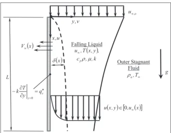
Consider a vertical permeable plate of lengthL. A fluid stream with free velocityu‘,oand thicknessHostarts to fall over the plate from its highest edge (entrance) as shown in Figure 1. Based on the Bernoulli equation,18 the fluid free stream velocityu‘will change outside the
velocity boundary layer of the plate according to the following relationship
u‘= u‘
u‘,o =
ffiffiffiffiffiffiffiffiffiffiffiffiffiffiffiffiffi
1+ 2x
Fr2 L s
ð1Þ
wherexandFrLare given by
x= x
L ð2Þ
FrL=
u‘,o ffiffiffiffiffiffiffiffiffiffiffiffiffiffiffiffiffiffiffiffiffiffiffiffiffiffi (1r
a=r)gL
p ð3Þ
x, g, and FrL are the coordinates along the plate length, gravitational acceleration, and effective Froude number, respectively.randraare the falling and exter-nal fluid densities, respectively. The following assump-tions are considered in this work: laminar flow, constant fluid properties, negligible axial diffusive terms, and negligible transverse variation in the pres-sure. The last two assumptions reveal the boundary layer assumptions. The falling liquid stream forms a developing region that has the following dimensionless continuity, momentum, and energy equations18,19
∂u
∂x+
∂v
∂y=0 ð4Þ
o ,
u∞
( )x
δ v , y Falling Liquid ( ) k , , c , y , x T , u
pρ μ
∞ u , x
( )x Vw Outer Stagnant Fluid ∞ T , a ρ g L
(x,y) [,u ( )x]
u ∈0 ∞
s y
q y T
k = ′′
∂ ∂ −
=0
u∂u
∂x+v ∂u ∂y =
1
Fr2 L
+ 1
ReL ∂2u
∂y2 ð5Þ
u∂u
∂x+v
∂u
∂y= 1
ReLPr ∂2u
∂y2 ð6Þ
whereu,v,y,u, andReLare given by
u= u
u‘,o
7ðaÞ
v= v
u‘,o
7ðbÞ
y= y
L 7ðcÞ
u=TT‘
q00 sL=k
7ðdÞ
ReL= ru‘,oL
m =FrL
ffiffiffiffiffiffiffiffiffiffiffiffiffiffiffiffiffiffiffiffiffiffiffiffiffiffi
1ra
r
Ga
s
ð8Þ
y is the normal position coordinate. u and v are the velocity components along the x- and y-coordinates, respectively.T andT‘are the liquid and the free stream
temperature fields, respectively.uandq00s are the dimen-sionless temperature and the applied heat flux which is constant, respectively.Pr and mare the liquid Prandtl number and dynamic viscosity, respectively. ReL is a reference Reynolds number. Ga is the Galilei number. This number is defined as follows
Ga=r 2
gL3
m2 ð9Þ
The permeable plate is considered to be subjected to nonuniform surface suction with surface suction velo-cityVwequal to
Vw=Vo(m+1)xm ð10Þ
whereVo is the average surface suction velocity and m is the power-law index. The boundary conditions of the present problem are the following
u(x,0) =0 11ðaÞ
v(x,0) = Vw= Vw u‘,o
11ðbÞ
∂u ∂y
x,0
= 1 11ðcÞ
u(x,y!‘) =u‘ ð12Þ
∂u ∂y
x,y!‘
=0 ð13Þ
Equations (12) and (13) were derived based on fact that the liquid film is thicker than both the velocity and temperature boundary layers.
It should be mentioned here that when Pr.1, the
velocity boundary layer will be thicker than the tem-perature boundary layer. Thus, the temtem-perature profile will not be directly affected by the advection in inviscid region. However, when Pr\1, the velocity boundary layer will be thinner than the temperature boundary layer. For this case, the temperature profile will be more influenced by the advection in the inviscid region, as the free edge of the temperature boundary layer is located in the inviscid fluid region.
Nonsimilar transformation of the transport equations
Define the following independent and dependent variables
j= 2x
Fr2 L
ð14Þ
h=y x
ffiffiffiffiffiffiffi
Rex p
= y
x1=2
ffiffiffiffiffiffiffiffiffiffiffiffiffi
u‘ReL
p
ð15Þ
f0(j,h) = ∂f ∂h=
u
u‘ ð
16Þ
These variables transform equations (2)–(4) to the following nonsimilar equations
v(j,h) =
ffiffiffi j
p
u1‘=2FrLpffiffiffiffiffiffiffiffiffiffi2ReL
f
u‘
+2u‘ ∂f
∂j
j+2 4j(j+1)
hf0f
½
ð17Þ
f000+ 3j+2
4(j+1)
ff00 2 j
(j+1)
f021
=j f0∂f
0
∂jf 00∂f
∂j
ð18Þ
u00
Pr+
3j+2
4(j+1)
fu0=j f0∂u
∂ju 0∂f
∂j
ð19Þ
When applying the boundary condition given by equations 11(b) on equation (17) the resulting equation is an ordinary differential equation which when solved results in the following equation
f(j,0) =Vo Fr2
LGa 1
ra r
1=4
Fr2 L 2 m+ 1 2
jm+12
(j+1)1=4
" #
, m.0
ð20Þ
The boundary conditions given by equations 11(a, c)–(13) are transformed to
u0(j,0) = j
1=2
(j+1)1=4
" #
Fr2 L
4Ga(1r
a=r)
1=4
ð22Þ
f0(j,h!‘) =1 ð23Þ
u0(j,h!‘) =0 ð24Þ
Equation (18) along with its boundary conditions reduces to the following whenj=0
f000(0,h) + 1 2f(
0,h)f00(0,h) =0 ð25Þ
f(0,0) =0, f0(0,0) =0, f0(0,h!‘) =1 ð26Þ
Equation (25) is the Blasius equation.19,20 Furthermore, equation (19) can be solved analytically whenj=0. Its solution is given by
u(0,h) =0 ð27Þ
The flow and heat transfer performance numbers. The local skin friction coefficient (Cf) and local Nusselt number (Nu) are given by
Cf=
m ∂u=∂yj y=0
ru2
‘=2
=2f 00(j,0)
ffiffiffiffiffiffiffi Rex p = 2 ffiffiffi 2 p
f00(j,0)
FrL3=2 1ra
r
(j+1)Ga
h i1=4
j1=2
ð28Þ
Nu=hx
k = Fr2 L 2 j u(j,0)
ð29Þ
The average values ofCf andNuare given by
Cf=
m ∂u=∂yj y=0
ru2
‘,o=2
= Frffiffiffiffiffiffiffiffiffiffi2L
ReL
p
ð 2=Fr2
L
0
2f00(j,0)½1+j3=4
j1=2 dj
ð30Þ
NuL[
hL
k =
ð 2=Fr2
L
0
Nu(j)
j dj ð31Þ
The heat transfer enhancement indicators
Let the first heat transfer enhancement indicator l be defined as ratio of the boundary excess temperature for reference case (Vw=0) to that quantity when Vw6¼0. It is written as
l=u(j,
0)j
Vw=0
u(j,0) = Nu NujVw=0
ð32Þ
Since the applied heat flux is constant, heat transfer is already known in advance. The enhancement in heat transfer that is indicated by l will occur if it is larger than 1. This means that the plate temperature is colder than that of the typical case where there is no suction. Accordingly, the applied heat flux can be increased to raise the plate temperature in order to reach that of the latter typical case.
The second performance indicatorgis defined as the ratio of the boundary excess temperature for the perfect fluid-slip case to that quantity under no-slip condition. Mathematically, it is given by
g=us(j,0) u(j,0) =
Nu
Nus ð
33Þ
The energy equation for the perfect fluid-slip at the
solid boundary (ideal case)
When perfect slip is present between the plate and the liquid, equation (6) reduces to
u‘
∂us
∂x
Vw+
y
u‘Fr
2 L
∂
us ∂y =
1
ReLPr ∂2us
∂y2 ð34Þ
whereusis the dimensionless temperature field for this case, us= (TsT‘)(k=½q00sL). Applying the following independent variable
hs=ypffiffiffiffiffiffiffiffiffiffiffiffij+1 ð35Þ
to equation (34) results in the next partial differential equation 1 Pr FrL ffiffiffiffiffiffiffiffiffiffiffiffiffiffiffiffiffiffiffiffiffiffiffiffiffiffiffi (1r
a=r)Ga p
" #
∂2us
∂h2 s
+
VwFr 2 L ffiffiffiffiffiffiffiffiffiffiffiffi j+1 p ∂∂us
hs =
2
ffiffiffiffiffiffiffiffiffiffiffiffi j+1 p ∂∂us
j
ð36Þ
The reduced boundary conditions are given by
∂us
∂h s
j,hs=0
= ffiffiffiffiffiffiffiffiffiffiffiffi1 j+1 p , ∂us
∂h s
j,hs!‘
=0 ð37Þ
us(j=0,hs) =0 ð38Þ
Numerical methodology validations and
results
Numerical methodology
equation which is reduced to second-order partial dif-ferential equation by letting F=f0. Also, equations (18) and (19) are linearized and consequently discre-tized using three-point central different quotients for all derivatives in theh-direction. The following lineariza-tion models are used to linearizefF0andF222
fF0=fn1F0 ð39Þ
F2
=2Fn1 FFn1 2 ð40Þ
whereFn1
and fn1
are the values of F andf at the previous iteration, respectively. The resulting discre-tized equations at given j value form tridiagonal sys-tems of algebraic equations that can be easily solved using Thomas algorithm.21 Next, the differential equa-tionF=f0 is solved using the trapezoidal rule.23Since equation (18) is nonlinear, an iterative procedure is required to obtain its exact solution at givenj. A maxi-mum relative error in computingFof106was
consid-ered as a convergence criterion. The following iterative scheme is used
Fn=bFn1+ (1b)F ð41Þ
whereb is taken to beb=0:6. Solutions of equations
(18), (19), and (36) march from j=0 to j=2=Fr2
L using two-point backward different quotient for the first derivatives in thej-direction. The step sizes in the j- andh-directions are taken to beDj=0:002=Fr2
Land
Dh=0:0025, respectively.
Validations and numerical results
For large and uniform suction velocity, equations (5) and (6) reduce to
d2 (u,u)
dy2 +
VwReL(1,Pr)
d(u,u)
dy =0 42ða;bÞ
The solutions to these equations result inf00(j,0) and Nuxequal to
Lim
VoReL!‘
f00(j,0)
½ =
Vw ffiffiffi
2 p
Fr3L=2 1ra
r
Ga
1=4
j1=2 (j+1)1=4
" #
ð43Þ
Lim
VoReL!‘
Nu(j)
½ =VwPr
Fr3 L
2
1ra
r
Ga
1=2
j ð44Þ
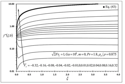
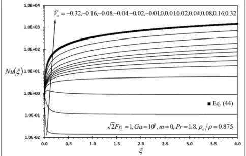
The plots of Figures 2 and 3 that are indented by
Vo=0:32 show the comparison between f00(j,0) and
Nu(j) computed using the proposed numerical method and those computed by equations (43) and (44), respec-tively. The maximum relative difference between the compared results is equal to2:3% when 0:059j4.
This led to large confidence in the obtained numerical solutions of this work which are shown in Figures 2–14.
Discussion of the results
Influence of average suction velocity on flow and heat
transfer characteristics
Figure 2 shows the effects of the average suction velo-city Vo on f00(j,0) that is linearly proportional to the skin friction coefficient at givenj-value. It is seen from this figure that f00(j,0) increases as Vo increases since
the velocity boundary layer thickness decreases as Vo increases.7WhenVo\0and is near the plate entrance, wall blowing affects wall shear stress more than the
shear force at boundary layer interface sinceu‘is small in this region. This effect causesf00(j,0) to decrease asj
increases. However, far downstream, the shear force at the boundary layer interface affects the wall shear stress more than the wall blowing since u‘ is large there and this causes f00(j,0) to increase as j increases.
Accordingly, f00(j,0) has a local minimum value near
the plate upper edge when Vo\0. It should be men-tioned here that the wall blowing tends to decrease wall shear stress when free stream velocity is constant.
Figure 3 shows that the Nusselt number increases as
Vo increases. When Vo.0, Nu increases as j increases
due to the increase in the free stream velocity. For large values of j jVo when Vo\0, the blowing effect signifi-cantly widens the boundary layer thicknesses causing insignificant influence of free stream velocity on heat transfer. Thus,Nudecreases asjincreases. For moder-ate values of j jVo when Vo\0, the counter-effects of blowing and free stream accelerating velocity on heat transfer result in having local maximum value of Nu
close to the upper end. This is clearly shown in Figure 3 for the plot with Vo= 0:08. Also, Figure 3 shows thatNuincreases asjincreases whenj j Vo 0:04 and when Vo\0. This indicates that the role of the
Figure 3. Effects ofVoandjonNu(j).
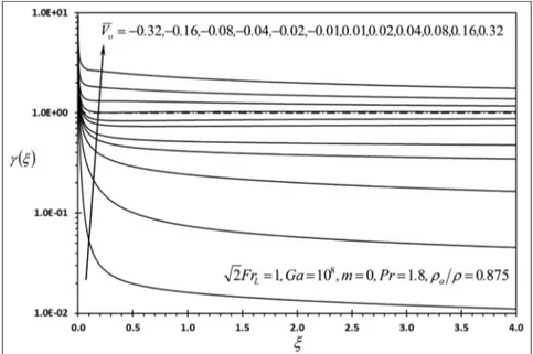
accelerating free stream velocity on heat transfer is dominating over the role of the blowing effect along the whole length of the plate. Figure 4 illustrates that heat transfer enhancement is ensured whenVo.0since l.1along the whole plate length whenV
o.0. Figure 5 demonstrates that the present system has better enhancement ratio than the case with perfect fluid-slip at the surface whenVo 0:04. It is because that perfect fluid-slip condition at the surface tends to increase the convection heat transfer coefficient leading to reduction in excess surface temperature. This causes reduction in the transverse convection due to surface suction. Note
that this transverse convection is proportional to rcpVw(TsT‘).
Influence of suction power-law index on flow and
heat transfer characteristics
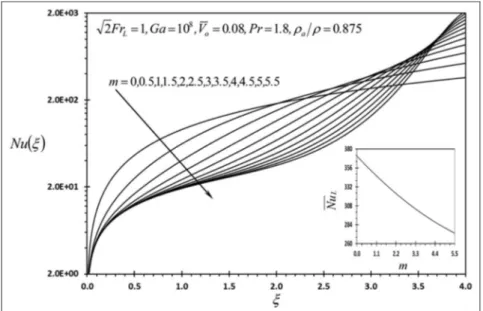
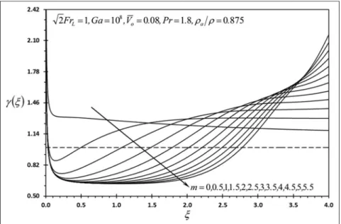
Figures 6–9 show thatf00(j,0),Nu,l, andgdecrease as m increases near the upper end (entrance) while they increase as m increases close to the lower end (exit). The average value of the skin friction coefficientCf is shown from Figure 6 to increase asmincreases, while Figure 7 shows that the average value of the Nusselt
Figure 5. Effects ofVoandjong(j).
number Nu decreases as m increases. All values of m
whenm.0result in l.0as shown in Figure 8. Figure
9 demonstrates that asmincreases, the extension of the plate from the lower end that results ing.0decreases.
This is because the surface suction velocity increases significantly at the lower end as m increases. This results in increasing the transverse convection. However, the perfect fluid-slip condition at the surface tends to additionally increase the convection coefficient leading to further reduction in excess surface tempera-ture. This causes reduction in the transverse convection due to surface suction as this convection is propor-tional torcpVw(TsT‘). Table 1 shows the variation in
the required effective Froude number with uniform
surface suction velocity case necessary to obtain the same Nusselt at the lower end for the case having non-zero power-law index m. This value is denoted by
FrLjNuL,m=0. It is shown that FrLjNuL,m=0 increases as
both m and Vo increase. The variation in FrLjNuL,m=0
withGais noticed to be insignificant for large values of
Vo. This table shows that properly distributing the sur-face suction velocity can save large flow work energy necessary to obtain the same temperature of the lower end as FrLjNuL,m=0=FrL reached values above 6 when
Vo=0:08 and m=6:0. The values of FrLjNuL,m=0 are
obtained as follows: (1) the present problem is solved for wide range of FrL for a given Vo with m=0, (2)
NuL,m=0 is correlated to FrL for the given Vo, (3) the
Figure 7. Effects ofmandjonNu(j).
present problem is solved for a givenFrL and Vo with variousmvalues, and (4)NuLfor a givenmis set to be equal to NuL,m=0 and is substituted in the aforemen-tioned correlation in order to obtainFrLjNuL,m=0. The
generated correlation is of the following form
FrLjNuL,m=0=
a1+a2NuL,m=0+a3½NuL,m=0 2
1+a4NuL,m=0+a5½NuL,m=0 2
+a6½NuL,m=0 3
ð45Þ
The correlation coefficients for four different cases that produce correlation coefficient equal toR2=1are
shown in Table 1. For large Vo values, equation (44) can be used to show that
Lim
VoReL!‘
FrLjNuL,m=0
= (m+1)FrL ð46Þ
Lim
VoReL!‘
(lL) =m+1 ð47Þ
Influence of Galilei and Froude numbers on flow and
heat transfer characteristics
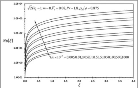
Figures 10–13 show thatf00(j,0),Nu,l, andg increase
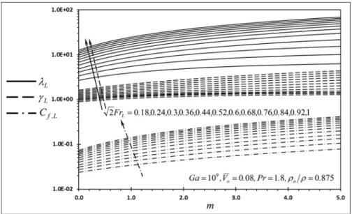
as Ga increases. Also, Figure 14 shows that Cf,L, lL, andgLincrease as FrLincreases. The increase inGa is
Figure 9. Effects ofmandjong(j).
achieved by the increase in bothr andra under same ra=rratio, while the increase inFrL is achieved by the increase in u‘,o. Figure 12 shows that allGa numbers resulted in l.1. Furthermore, it is shown from
Figure 13 thatgbecomesg.1whenGa53107 . It is because the boundary layer thickness increases as Ga
increases. Thus, the excess temperature becomes more apparent asGaincreases compared to that for the per-fect fluid-slip condition at the surface. This efper-fect tends to increase the transverse convection as that convection is proportional torcpVw(TsT‘). Figure 14 shows that
Cf,L,lL, andgL become less sensitive to FrL for large
FrLnumbers.
Conclusion
The problem of laminar flow and heat transfer by forced convection inside the boundary layers of a gravity-driven liquid film on a vertical permeable plate subject to nonuniform surface suction was analyzed. A constant wall heat flux was assumed at the plate. A power-law functional form was considered to model
Figure 11. Effects ofGaandjonNu(j).
the surface suction velocity. Nonsimilar continuity, momentum, and energy equations were obtained using properly selected transformation variables. These equa-tions were solved numerically using an implicit, itera-tive, and finite difference method. Excellent agreement was obtained between the present results and those for asymptotic analytical solutions. It was found that increases in the Froude number, Galilei number, and dimensionless average suction velocity cause increases in the skin friction coefficient, Nusselt number, and heat transfer enhancement ratios. The heat transfer
enhancement ratios computed at the lower end of the plate were noticed to increase as the suction power-law index increases. The Froude number for the uniform surface suction case that is necessary to attain the same heat transfer enhancement ratios due to nonuniform surface suction distribution was found to increase as the Galilei number, average suction velocity, and power-law index increase. The upper most values of the enhancement factors in heat transfer and Froude num-ber were found to be m+1 fold when the suction
power-law index is equal tom. The results of this work
Table 1. Values of Froude number atm=0 required to have the same Nusselt number at the bottom end(FrLjNuL,m=0)when
m6¼0,Pr=1:8, andra=r=0:875.
Ga=13108 Ga=1
3109
Vo FrL m NuL FrLjNuL,m=0 FrLjNuL,m=0
FrL
Vo FrL m NuL FrLjNuL,m=0 FrLjNuL,m=0
FrL
0.04 1
ffiffi
2
p 0 188.6 0.7071 1.0000 0.04 1
ffiffi
2
p 0 574.3 0.7071 1.0000
0.5 254.5 0.9816 1.3882 0.5 833.5 1.0373 1.4670
1.0 316.6 1.2343 1.7455 1.0 1095 1.3693 1.9365
1.5 373.1 1.4621 2.0677 1.5 1355 1.6988 2.4025
2.0 423.6 1.6646 2.3540 2.0 1611 2.0234 2.8615
2.5 468.2 1.8431 2.6065 2.5 1862 2.3419 3.3120
3.0 507.4 2.0001 2.8285 3.0 2107 2.6542 3.7536
3.5 542.0 2.1383 3.0240 3.5 2347 2.9603 4.1865
4.0 572.6 2.2603 3.1966 4.5 2583 3.2603 4.6107
4.5 599.7 2.3686 3.3497 5.0 2813 3.5544 5.0267
5.0 623.9 2.4652 3.4863 5.0 3039 3.8429 5.4346
5.5 645.6 2.5519 3.6089 5.5 3261 4.1258 5.8347
6.0 665.2 2.6301 3.7195 6.0 3478 4.4032 6.2270
Equation (45) constants
a1=0:985107 a2=7:764243103
a3=2:509833104 a4=0:0657433
a5=2:678893106 a6=9:0888431010
Equation (45) constants
a1=0:844762 a2=5:359143104
a3=1:104983104 a4=
0:0890351 a5=7:081323107 a6=
6:7043931011
Ga=13108 Ga=1
3109
Vo FrL m NuL FrLjNuL,m=0 FrLjNuL,m=0
FrL
Vo FrL m NuL FrLjNuL,m=0 FrLjNuL,m=0
FrL
0.08 1
ffiffi
2
p 0 361.9 0.7071 1.0000 0.08 1
ffiffi
2
p 0 1130 0.7071 1.0000
0.5 528.7 1.0426 1.4744 0.5 1671 1.0525 1.4884
1.0 696.9 1.3804 1.9522 1.0 2204 1.3936 1.9708
1.5 864.5 1.717 2.4282 1.5 2728 1.7309 2.4478
2.0 1030 2.0506 2.8999 2.0 3244 2.0646 2.9197
2.5 1194 2.3803 3.3663 2.5 3753 2.3944 3.3861
3.0 1356 2.7061 3.8270 3.0 4254 2.7201 3.8468
3.5 1515 3.0279 4.2821 3.5 4748 3.0417 4.3016
4.0 1672 3.3458 4.7317 4.0 5233 3.3590 4.7504
4.5 1828 3.6599 5.1758 4.5 5711 3.6721 5.1931
5.0 1980 3.9701 5.6146 5.0 6182 3.9808 5.6296
5.5 2131 4.2767 6.0481 5.5 6645 4.2851 6.0606
6.0 2280 4.5795 6.4764 6.0 7101 4.5851 6.4843
Equation (45) constants
a1=0:145118 a2=2:164643103
a3=9:344593105 a4=0:0470735
a5=2:613863107 a6=0
Equation (45) constants
a1=0:010594 a2=6:908033104
a3=6:672183106 a4=0:0106232
a5=5:857563108 a6=
demonstrate that significant heat transfer enhancement inside the boundary layers is attainable when properly distributing the suction velocity along the plate.
Declaration of conflicting interests
The author declares that there is no conflict of interests regarding the publication of this article.
Funding
This article was funded by the Deanship of Scientific research (DSR), King Abdulaziz University, Jeddah. The author, therefore, acknowledges with thanks DSR’s technical and financial support.
References
1. Sick F, Bushulte TK, Klein SA, et al. Analysis of the sea-sonal performance of hybrid desiccant cooling systems.
Sol Energy1988; 40: 211–217.
2. Ali A, Vafai K and Khaled ARA. Analysis of heat and mass transfer between air and falling film in a cross flow configuration. Int J Heat Mass Tran 2004; 47: 743–755.
3. Mei L and Dai YJ. A technical review on use of liquid-desiccant dehumidification for air-conditioning applica-tion.Renew Sust Energ Rev2008; 12: 662–689.
4. Dabir B, Riazi MR and Davoudirad HR. Modelling of falling film reactors.Chem Eng Sci1996; 51: 2553–2558.
Figure 13. Effects ofGaandjong(j).
5. Talens-Alesson FI. The modelling of falling film chemi-cal reactors.Chem Eng Sci1999; 54: 1871–1881.
6. Zhang H, Chen G, Yue J, et al. Hydrodynamics and mass transfer of gas–liquid flow in a falling film micro-reactor.AIChE J2009; 55: 110–1120.
7. Pop I, Watanabe T and Konishi H. Gravity-driven lami-nar film flow along a vertical wall with surface mass transfer.Int Commun Heat Mass1996; 23: 685–695. 8. Anderson HI and Irgens F. Gravity-driven laminar film
flow of power-law fluids along vertical walls.J Non-New-tonian Fluid1988; 27: 153–172.
9. Yih SM and Lee MW. Heating or evaporation in the thermal entrance region of a non-Newtonian, laminar, falling liquid film. Int J Heat Mass Tran 1989; 29: 1999–2002.
10. Shang D.Free convection film flows and heat transfer— models of laminar free convection with phase change for heat and mass transfer analysis. 2nd ed. New York: Springer, 2012.
11. Shang D. Theory of heat transfer with force convection film flows. New York: Springer, 2011.
12. Sparrow EM and Gregg JL. A boundary layer treatment of laminar film condensation. J Heat Trans: T ASME
1959; 81: 13–18.
13. Andersson HI and Ytrehus T. Falkner-Skan solution for gravity-driven film flow.J Appl Mech: T ASME1985; 52: 783–786.
14. Jalil A, Hossain A, Reza M, et al. Study of gravity-driven film flow with variable physical properties along an inclined wall.Int J Sci Eng Res2013; 4: 1346–1354. 15. Ahmad K, Nazar R and Pop I. Falkner-skan solution for
gravity-driven film flow of a micropolar fluid. Sains Malays2011; 40: 1291–1296.
16. Khaled ARA. Mathematical and numerical analysis of heat transfer enhancement by distribution of suction flows inside permeable tubes.Math Probl Eng2015; 2015: 953604-1–953604-11.
17. Bergles AE. Chapter 11: techniques to enhance heat transfer. In: Rohsenow WM, Hartnett JP and Cho YI (eds) Handbook of heat transfer. New York: McGraw-Hill, 1998, p. 11.55.
18. Durst F.Fluid mechanics: an introduction to the theory of fluid flows. Berlin, Heidelberg: Springer-Verlag, 2008. 19. Bejan A. Convective heat transfer. 2nd ed. New York:
Wiley, 1995.
20. Oosthuizen PH and Naylor D.Introduction to convective heat transfer analysis. New York: McGraw-Hill, 1999. 21. Blottner FG. Finite-difference methods of solution of the
boundary-layer equations.AIAA J1997; 8: 193–205. 22. Arpaci VS and Larsen PS.Convection heat transfer. New
York: Prentice Hall, 1984.
23. Atkinson KE.An introduction to numerical analysis. 2nd ed. New York: John Wiley & Sons, 1989.
Appendix 1
Notation
a1a6 correlation coefficients
(Cf,Cf) (local, average) skin friction coefficient (cp,k) fluid (specific heat, thermal conductivity
(J kg21
K21
, W m21
K21
)
(f,f0) transformed (stream function,uvelocity)
FrL effective Froude number
g gravitational acceleration (m s22
)
Ga Galilei number
(h,hs) local convection coefficient for (present, perfect slip) case (W m22
K21
)
h average convection heat transfer
coefficient (W m22
K21
)
L length of the plate (m)
m Power-law index
(Nu,Nus) Nusselt number for the (present, perfect slip) case (Nus,x=hsx=k)
NuL average Nusselt number (NuL=hL=k)
Pr fluid Prandtl number (Pr=mcp=k)
q00s surface heat flux (W m22
)
Re Reynolds number
(T,T‘) (fluid, free stream) temperature field (K)
(u,u‘,u‘,o) (local, free stream, entrance) velocity along thex-direction (m s21
)
(u,u‘) dimensionless (u,u‘) velocity (u=u=u‘,o) (Vo,Vw) (average, local) surface suction velocity (m
s21
)
(Vo,Vw) (average, local) dimensionless suction velocity (V(o,w)=V(o,w)=u‘,o)
(v,v) (dimensional, dimensionless) normal velocity (m s21
)
(x,y) (longitudinal, transverse) axis (m) (x,y) dimensionless (longitudinal, transverse)
axis (x=x=L,y=y=L)
Greek symbols
(g,l) (second, first) heat transfer indicator (d,d) (dimensional, dimensionless) boundary
layer thickness ((m),d=d=L) hs transformedyvariable for the perfect
fluid-slip condition (h,j) transformed (y,x) variable
m dynamic viscosity of the falling fluid (kg m21
s21
)
(u,us) dimensionless fluid temperature for (present, perfect slip) case