Con tribution s of Strain En ergy an d
PV-w ork
on the
Ben din g Behavior of Un coated Plain -woven Fabric Air
Beam s
Paul V. Cavallaro1, Ali M. Sadegh, Ph.D.2, Claudia J. Quigley3
1
U.S. Naval Undersea Warfare Center, Division Newport, Newport, Rhode Island USA
2
The City College of The City University of New York, New York, NY USA
3
U.S. Army Research, Development and Engineering Command, Natick, Massachusetts USA
Correspondence to:
Ali M. Sadegh, Ph.D. email: [email protected]
____________________________________________________________________________________________
ABSTRACT
The bending performance of fabric air beams varies significantly from conventional beams. Both are dependent upon the constitutive relations of the material, but air beams are further dependent upon the thermodynamics of the internal air. As the governing energy balance demonstrates, air beam bending is dependent upon strain energy and PV-work (air compressibility). The relative importance of these terms will vary with pressure, volume changes and shear deformations. To this point, a swatch of uncoated plain-woven fabric was subjected to mechanical tests and its material properties determined. Attempts at using the stress-strain measurements in air beam models, assumed constructed with the same fabric, were made. The models accounted for fluid-structure interactions between the air and fabric. Homogenization methods were used and were necessary to provide computational efficiencies for the macro-scale air beam model while attempts were made to incorporate the combined extension and shear behaviors observed during the material tests. Bending behavior was numerically investigated for several constitutive cases. The models were solved with the ABAQUS -Explicit program over a range of pressures. The fabric strain energy and PV-work were tracked and compared. It was concluded that strain energy and
PV-work must be considered in deflection analyses of uncoated plain-woven fabric air beams.
INTRODUCTION
Plain-woven fabrics have been utilized as structural materials in air-inflated systems resulting in rapidly deployed structures, such as temporary shelters and bridges, pneumatic muscles and actuators, large-scale energy absorbers and space antenna systems. Unlike metallic structures, air-inflated structures are primarily designed to be lighter weight, have
significantly large deployed-to-stowed volume ratios, provide fail-safe collapse mechanisms, may be self-erecting and designed to operate with optional rigidification methods. These applications typically employ pressurized fabric tubes (known as air beams) as their fundamental load-carrying members.
Air beams are tensioned structures consisting of an outer fabric layer and internal membrane-like bladder that enclose a pressurized volume of air. The air pressure develops a biaxial pre-tensioning stress throughout the fabric which in turn enables the air beam to generate its cylindrical shape, provides stiffness to resist deflections from external loads and affords stability against collapse. Air beams often utilize a woven or braided fabric construction consisting of discrete tows or yarns interlaced with prescribed levels of periodicity. Unlike conventional structures, predictive performance methods for fabric air beams are not well established. This is further exacerbated for air beams constructed of uncoated woven fabrics in which kinematic changes in the weave architecture (yarn slip, rotation and crimp interchange) from external loads and thermodynamic effects (PV-work) significantly influence bending and shear behavior. A fundamental distinction between braided and uncoated woven fabrics is that the shear stiffness of the latter is not related to the elasticity of the yarns. Rather, it is a kinematic property of the yarn assemblies involving rotations and contact pressures among yarn families at the crossover points. Further research is necessary in both experimental characterization and constitutive modeling methods for uncoated plain-woven fabrics.
LITERATURE REVIEW
Fichter [2], and Bulson [3]. The fabric was assumed to be a homogenous continuum that and incapable of supporting compressive stresses. The wrinkling moment was easily derived for inflated woven fabric beams through moment equilibrium as
π
PR3/2, where P is the pressure and R is the radius. Steeves [4-9] later investigated the bending behavior of “pressure-stabilized” beams through analysis and bending experiments. In addition, Steeves conducted mathematical modeling and testing of biaxially-loaded woven fabrics and developed a finite element specifically for air beams. Freeston, et al [10], conducted both theoretical and experimental research on the stress-strain behavior of plain-woven fabrics subjected to biaxial loads. Analytical expressions, initially based on Pierce’s [11] geometric fabric model for circular yarns, were derived to establish parameters influencing biaxial deformations. Veldman [12] provided a summary of inflatable structures technologies and presented both analytical and numerical modeling methods for establishing bending behavior of inflated cylindrical beams. These models were validated using bending experiments performed on thin film inflatable beams and beams constructed of uncoated braided carbon yarns with axial reinforcements. Mechanical properties for the models were obtained from biaxial tests of cruciform-shaped specimens. While the biaxial test results showed that the film materials behaved as an orthotropic continuum, the fixture did not permit measurements of shear modulus as functions of biaxial tensile stress. Main, et al [13, 14] conducted cantilevered bending tests of inflated beams constructed of woven nylon rip-stop fabric. A numerical code was used to directly solve the Euler-Bernoulli bending differential equation with the required elastic modulus initially obtained from uniaxial tension tests and subsequently from inflated cylinder extension tests. Their solutions did not address shear deformations or changes in air pressure and volume during bending.Considerable research has been performed on numerical methods based upon unit cell and other micro-scale modeling techniques to predict the behavior and effective mechanical properties of various fabric architectures to applied loads. Sidhu, et al [15], developed a numerical modeling method coupled with experimental tests to evaluate the performance of composite pre-forms constructed of plain-woven tows. Their method was based on a unit cell geometry that used a mixture of truss and shell elements. King, et al [16] developed a shell formulation for numerically modeling the deformation behavior of woven fabrics and
conducted experimental validation tests including biased fabric extension, yarn bending and fabric twist. Tarafaoui and Akesbi [17] developed a finite element unit cell model and simulated the tensile and pure shear tests of fabrics. Quigley, et al [18] demonstrated the use of their fabric strip method to predict the elastic and shear moduli for uncoated plain woven fabrics subjected to combined biaxial tension and shear loads. Vandeurzen [19] proposed a method of predicting the shear modulus for woven fabric composites. Farboodmanesh, et al [20] conducted pure shear testing of both uncoated and rubber-coated woven fabrics. Woo [21, 22] developed a global/local finite element model for textile composites. Kuhn, Charalambides [23] and Kuhn, et al. [24] presented unit cell geometries and addressed the modeling of plain woven fabrics. Ruan and Chou [25] performed experimental and theoretical studies of the failure behavior of knitted fabric composites. Hahn and Pandey [26] presented a micromechanical model to predict thermoelastic properties of plain-woven fabric composites. Li, et al. [27] analyzed two models, based on geometric modeling, to predict the fiber orientation of biaxially braided fabrics. Klute and Hannaford [28] developed a finite element model and investigated pneumatic (artificial muscle) actuators. Cavallaro, et al [29,30] developed unit-cell models for uncoated woven fabric air beams and showed that the elastic and shear moduli were independent of the elastic modulus of the yarns for a range of safe operating pressures but were dependent upon inflation pressure, fabric construction and crimp interchange.
and limitations of these cases for an uncoated plain-woven fabric.
NOMENCLATURE
Aweft weft yarn cross sectional area
Awarp warp yarn cross sectional area
C crimp content
load_pt load point displacement
mid mid-span deflection
strain due to equi-biaxial extension
E elastic modulus
Eart artificial strain energy
Edis viscous dissipation energy
Eint internal energy
Estrain strain energy
Ekinetic kinetic energy
Etan tangent modulus
Einst instantaneous modulus
Freact sum of load point reaction forces
G shear modulus
γ shear strain
Lfabric reference length of yarn in fabric
Lyarn length of yarn extracted from fabric
Mwrinkle wrinkling moment
0 initial hyperelastic shear modulus Poisson’s ratio
P inflation pressure warp warp direction stress weft weft direction stress
crimp ratio
r radius of cylinder
S stress ratio
SC converged stress ratio shear stress
V air volume
Wext external work done YDR yarn density ratio
MATERIAL DESCRIPTION & SWATCH-LEVEL TESTS
A: Material Description
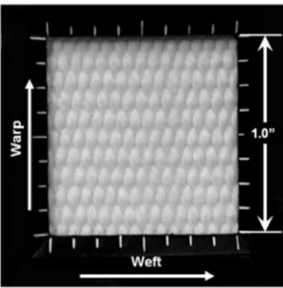
A commercially available fire hose fabric was selected for this study. The fabric was a dense, high-quality, uncoated, plain-woven polyester material, as shown in Figure 1. The warp yarns were aligned in the longitudinal direction of the fire hose and the weft yarns, orthogonal to the warp yarns, were aligned in the hoop direction. Specific details at the yarn and fabric levels were measured and reported in
Table 1.
FIGURE 1. Uncoated plain-woven polyester fabric
TABLE I. Details of the polyester yarns and uncoated plain-woven fabric
The crimp ratio, denoted as
ξ
in Table I., is defined as the ratio of the crimp value in the weft direction to that of the warp direction. Crimp content, C, is the waviness of the yarns and was obtained by measuring the length of a yarn in its fabric state, Lfabric, and the length of that same yarn after it was extracted from the fabric, Lyarn, and straightened out according to Eq. (1).fabric fabric yarn
L
L
L
C
=
−
(1)B: Swatch-Level Tests
The constitutive behaviors of fabrics used in inflatable structures are sensitive to pressure-induced biaxial tensions upon inflation and to shearing stresses resulting from external loads. Therefore, it is necessary to evaluate the mechanical properties of the fabric about combined biaxial tension and shear stress fields. Recently, Cavallaro, et al [32] developed the combined biaxial tension and shear test fixture shown in Figure 2 to enable swatch-level material property measurements about these combined stress fields. The test fixture consists of two rhombus-shaped four-bar linkage systems that are pivotally connected to one another at the top and the bottom vertices through four sleeve bearings. Each sleeve bearing is pivotally connected to the two adjacent members of the rhombus-shaped linkages at its superior and inferior vertices. Four loading plates are pivotally attached to each of the two lateral vertices of each of the rhombus-shaped four-bar linkages. A gripping/clamping mechanism is attached to the distal end of each of the loading plates. The top and the bottom of the test fixture is attached to a standard testing machine such as an Instron®.
The fixture is capable of applying biaxial tension or compression loads optionally combined with an in-plane shear load. It can be used to test a variety of materials, including metals, plastics, textiles, composites, woods, etc. The advantages of this fixture is that a standard uniaxial tensile or compressive load of a test machine can be converted to an equi-biaxial extension or contraction with orthogonal or oblique orientations on a planar test specimen by use of two load transfer systems consisting of rhombus-shaped four-bar linkages. The in-plane shear load can be applied either simultaneously or independently of the biaxial tension or compression load by rotating the rhombus linkages with respect to one another.
Forces along the warp and weft yarn directions are measured using strain gauges attached to the loading plates. Calibration curves of force-versus-strain were obtained from previously conducted tests of the loading plates to enable the conversion of strain values to force values. Stresses are then obtained by dividing the force in each direction with the corresponding total cross-sectional areas of all yarns for that direction. For the in-plane shear load, the angle of rotation of the two rhombus-shaped linkages is measured directly by the test machine through load cells or other conventional instrumentation. For purpose of reference, the warp and weft directions
shown in Figures 1 and 3 correspond to the longitudinal and hoop axes, respectively, of the air beam models discussed in following sections.
FIGURE 2. Combined multi-axial and shear test fixture (U.S. Patent No. 6,860,156)
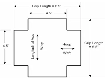
FIGURE 4. Uncoated plain-woven polyester fabric specimen subjected to combined biaxial tension and shear loads
The polyester fabric specimen, shown in Figures 3
and 4, was subjected to a series of tests including: (1) uniaxial tension along the warp direction, (2) uniaxial tension along the weft direction, (3) biaxial tension and (4) planar shear combined with biaxial tension. The biaxial experiments, (3) and (4) were performed in an equi-biaxial extension mode rather than, and in contrast to, an equi-biaxial force mode as the fixture does not support the latter at this time. Results of the uniaxial and biaxial tests (1-4) were plotted in Figure 5. Because the fixture used was an initial prototype, its maximum load was limited and therefore the fabric was not tested to failure.
Curves of biaxial force vs. equi-biaxial extension were plotted in Figure 6 to show the effects of multiple load cycles on reducing initial slack content. Successive load cycles were applied with decreasing magnitudes ensuring that fracture of the yarn filaments did not occur which would negatively influence the force-extension results. Slack reduction was observed through the migration of the curves towards the origin. The slopes of the force-extension curves beyond the yarn slippage region demonstrated excellent repeatability. The initial portions of the curves showed that slack in the warp and weft yarns can be minimized with multiple load cycles as the yarns progressively align in the direction of their respective tensions. Pre-conditioning through cyclic loading is especially recommended when conducting experimental load tests on uncoatedfabrics.
FIGURE 5. Uniaxial and biaxial stress-strain curves for plain-woven polyester fabric
FIGURE 6. Effect of preconditioning on the biaxial force vs. extension curves for plain-woven polyester fabric
The relative magnitudes of the warp (longitudinal) and weft (tangential) stresses are of great importance in air beam design. Thus the ratio of hoop stress per unit beam length to the longitudinal stress per unit circumference is defined as S. The variation of S
resulting from the equi-biaxial extension mode of testing was plotted in Figure 7, indicating that the ratio was neither controlled nor constant throughout the test. This was because the elastic moduli of the fabric were highly nonlinear with respect to extension (and strain). At the maximum equi-biaxial strain, , applied during the testing, S was 3.82, nearly twice the required value for properly characterizing the state of stresses in a pressurized cylinder. Note that S is equal to 2 for a pressurized cylinder with no external load.
pronounced differences between the uniaxial and biaxial curves for a given yarn family, as shown in
Figure 5, and b) the initial variation of the stress ratio
S as shown in Figure 7.
FIGURE 7. Stress ratio, S, versus equi-biaxial strain,
Due to the high non-linearity of the fabric stress-strain response, the elastic modulus of the fabric changes continually with inflation pressure. Denoting the instantaneous elastic modulus as Einst, the variation of Einstwith respect to the warp stress is conveniently shown in Figure 8. Since the inflation pressure of the air beam is related to the biaxial stress in the fabric, three states of the warp stress corresponding to 10, 15 and 20 psi have been identified on the curve. The initial kink of the curve
in Figure 8 is due to the slipping of the yarns.
FIGURE 8. Einst vs. σwarp where σwarp corresponds to the warp
direction stress-strain curve of Figure 5
Next, the shear stiffness of the fabric was evaluated as a function of 3 different biaxial extensions. This was accomplished by engaging the fixture’s in-plane shear mode while the fabric specimen was biaxially tensioned. One pair of rhombus-shaped frames was rotated with respect to the other thus generating a maximum shearing angle of approximately 10°. The resulting curves of shear stress, , versus shear strain,
γ, for each level of biaxial tension were plotted in
Figure 9. The forces denoted in this figure represent
the vertical compression load applied by the Instron machine to the fixture, FInstron, and the warp and weft directional forces Fweft and Fwarp, respectively. Note that test #2 of Figure 9 corresponds to an initial warp stress, σwarp of 637 psi (10-psi inflation pressure as shown in Figure 8).
FIGURE 9. vs. γ plot for three levels of equi-biaxial extension
The shear modulus, G, along path ab in the direction of increasing γ, for the three combined biaxial tension and shear test curves were derived by differentiating polynomial curve fits of Figure 9 and were plotted in
FIGURE 10. Shear modulus, G vs. shear strain, γ for three levels of equi-biaxial extension
Although the stiffening effects provided by increasing the biaxial tensions were clearly evident, initial reductions were pronounced in region I.
Figure 9 revealed three distinct regions of shear
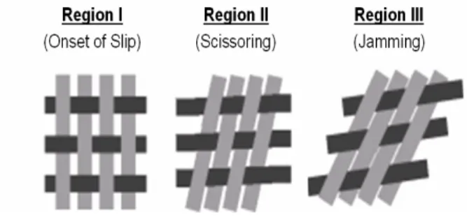
stiffness resulting from the scissoring kinematics between yarn families as shown in Figure 11.
FIGURE 11. Kinematics of shear deformations in uncoated plain-woven fabrics
Referring to region I of Figure 9, G was initially governed by compaction forces between the yarns at the crossover points due to the biaxial tensile stresses. As γ increased, yarn slip initiated and at γ equal to approximately 0.035 in/in, G substantially declined to minimal values. At this strain level, rotations between yarn families were met with minimal resistance to shearing rotations. This important observation is distinctly unique to uncoated fabrics and provides the basis for establishing coating methods for use in limiting
shearing deformations in air beams. Upon further increase of γ into region II, G increased as the gaps between yarn families diminished and the onset of shear jamming occurred. Region III is known as the shear jamming state. The onset of shear jamming, which can be determined through geometric models [11], is related to the maximum number of weft yarns that can be woven into the fabric for a given warp yarn size and spacing. The shearing behavior of this fabric was consistent with the numerical model and test results of the plain-woven fabric investigated in reference [30].
AIR BEAM FINITE ELEMENT MODEL
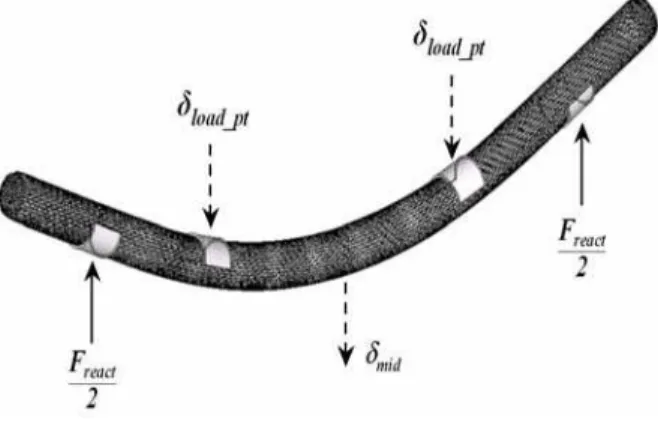
The air beam was modeled under 4-point bending with articulating saddles as shown in Figure 12. The models were developed with Altair’s HyperWorks [33] and solved with the ABAQUS-Explicit solver [34]. This solver captured the pressure-volume behavior of the internal air, transverse shear deformations during bending, geometric nonlinearities (due to large deformations, localized wrinkling and contact kinematics between the saddles and the air beam) and material nonlinearities for the hyperelastic material models. The internal bladder was considered non-structural and was not included in the current models. The articulating saddles were of 4.0-inch length, 2.135-inch inner radius and were assumed rigid.
Element selection for the fabric was critical to ensuring that the proper degrees of freedom were provided and only the applicable strain energy components were admissible in the formulation. The choice between shell or membrane elements was established based on the observation that the fabric sample evaluated in the swatch-level material tests was highly flexible. It was idealized as being incapable of developing bending strain energy and, therefore, the choice of using membrane elements to discretize the fabric was appropriate. The membrane element formulation did, however, support the extensional, planar shear and torsional shear components of strain energy. Had shell elements been chosen, an overly stiff bending response would have occurred. The membrane element thickness was computed based on an analogous homogeneous cylinder of 4.00-inch outer diameter and cross sectional area equivalent to the sum of the warp (longitudinal) yarn areas. The resulting thickness was 0.016 inches.
yarns, it remains computationally impossible at this time to explicitly model each yarn of an air beam so as to include the nonlinearities due to contact interactions at every yarn crossover point. Rather, the homogenization method was employed to enable the use of computationally efficient continuum elements (membranes) in macro-scale air beam models provided that their constitutive behavior preserved the nonlinearities observed during the swatch-level material tests. This approach, which is commonly used for analysis of heterogeneous materials such as composites and textiles, is further detailed with the micro-scale modeling techniques described in references [15-19 and 21-30].
FIGURE 12. Deformed model view of the plain-woven polyester fabric air beam subjected to 4-point bending
To model the fluid-structure interactions of the internal air and surrounding fabric, a pressurized cavity was defined along the inside surface of the fabric material. The cavity and its enclosing surface were used to apply the internal pressure, P, directly to the fabric (membrane) elements and to define the volume of air contained by the cavity within the air beam. The internal air was modeled as a compressible (pneumatic) fluid that satisfied the Ideal Gas Equation of State (EOS) as described in Appendix -A. This EOS assumed that compressibility of the air occurred adiabatically, that is, no heat transfer was permitted across the boundaries between the cavity and the fabric.
A 2-step loading process was used. During step #1, the air beam model was inflated to the specified pressures. In step #2, a lateral displacement, load_pt, of 6.00 inches (1.5 x diameter) was applied at both load points with the support points restrained from translating in all directions. The four saddles were
allowed to rotate so that their lateral reaction force vectors remained normal to the air beam at all times (i.e.; commonly referred to as follower mode of loading). A zero coefficient of friction was used at all contact surfaces so that relative slip between the air beam and saddles occurred without restriction. The distance between support point centerlines was 72.0 inches and the distance between loading point centerlines was 37.0 inches.
The external work, Wext, done on the air beam during a quasi-static 4-point bend test was computed as the area under the total reaction force, Freact, versus the enforced load point displacement, δload_pt, curve. During the bending step, Wext was equal to the change in internal energy of the air beam, ΔEint. The change in internal energy consisted of the sum of the changes in: fabric strain energy, ΔEstrain, kinetic energy of the total system mass, ΔEkinetic, work done by compressing the air, Δ∫PV, and viscous dissipation energy, ΔEdis, due to damping. (Note that Δrefers to the change between the bending and inflation end states). The governing energy balance is expressed as Eq. (2):
∫
=Δ= F d _ Eint
Wext react
δ
load pt (2)where:
∫
+
Δ
Δ
+
Δ
+
Δ
=
Δ
E
intE
strainE
kineticPV
E
disThe following sections will identify the importance for considering the contributions of ΔEstrain and Δ∫PV
on the deflections of air beams.
ANALYSIS & RESULTS
Specifically, the biaxial stress-strain curve along the warp direction shown in Figure 5 was used to formulate the elastic modulus of the membrane elements for two linearly elastic cases and the strain energy potential for one hyperelastic case. The three cases consisted of: (1) linear elasticity with E
assumed invariant with pressure (an idealization), (2) linear elasticity with Einst measured from Figure 8 for each pressure considered and (3) hyperelasticity. The hyperelastic case is the most general allowing for treatment of the entire nonlinear stress-strain curve and is applicable for post-wrinkled behavior. Note that the available constitutive models did not allow for independent treatment of the elastic and shear moduli and these cases were, therefore, limited to small shearing deformations.
The ABAQUS-Explicit solver was used for all cases.
Care was taken such that no natural modes of the structure were excited (i.e., the loads were applied slowly and ΔEkinetic was small). The advantage of using a dynamic solver is that if wrinkling or buckling events occurs, spikes in the ΔEkinetic time history curve would develop and would allow for easy detection of the event in time. Typically ΔEkinetic
and ΔEdis were observed to have negligible
contributions to Eq. (2) for the current effort. However, transverse shear deformations arising from the shearing strain γ will cause a reduction in air volume and will lead to additional PV-work [31].
Case #1 – Linear Elasticity, Constant Modulus For All Pressures
The value of E, arbitrarily taken as the largest tangent modulus of the warp direction biaxial stress-strain curve (0.1Mpsi) as shown in Figure 5, was assumed to be invariant with pressure and ν was set to 0.3 allowing for material compressibility. Here, the shear modulus, G, and elastic modulus, E, were related through a generalized form of Hooke’s Law as:
(
+
ν
)
=
1
2
E
G
where: ν is Poisson’s Ratio.
The time histories of pressure, internal volume, support-point reaction forces and energy terms necessary to conduct the energy balance of Eq. (2) were tracked during the solution. The change in pressure, ΔP, versus the corresponding change in volume, ΔV, during bending was plotted. The area under this curve was integrated to obtain the
PV-work.
For this linearly elastic case and the inflation pressures of interest, it was observed that ΔP and ΔV
were small. However, the contribution of PV-work
varied appreciably with pressure. Results indicated that ΔEstrain decreased with increasing P while the
PV-work increased with increasing P as shown in
Figure 13 for the specified load_pt. At pressures
below 30 psi, PV-work contributed less than 10% of
Wext and ΔEstrain was the dominant term in the energy balance contributing more than 90%. For these pressures, accurate mechanical property measurements of the fabric material are critical to deflection predictions. For pressures ranging between 30-90 psi, both ΔEstrain and PV-work are relevant and should both be considered although to a lesser extent as ΔEstrain contributed less with increasing pressure. Finally, for inflation pressures of 90 psi and greater, PV-work dominated the energy balance exclusively and the effects of ΔEstrain on bending were negligible. Hence, the usefulness of a linearly elastic material assumption on bending behavior is especially applicable for air beams at high pressures (>90 psi).
FIGURE 13. Wext, PV-work and ΔEstrain vs. P for a linearly elastic fabric (Case #1)
2
3
r
P
M
wrinkle=
π
(3)
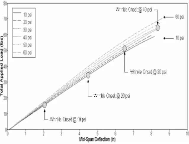
The wrinkling onsets observed in the model as shown
in Figure 14 were consistent with the theoretical
values obtained from Eq. (3). Note that wrinkling did not occur for inflation pressures above 40 psi at mid-span deflections equal to two diameters. The applicability of this constitutive case is limited to pre-wrinkled air beams in which E is negligibly effected by inflation pressure.
FIGURE 14. Freact, versus mid curves for linear elastic material model with P at 10 to 60 psi (Case #1)
Case #2 – Linear Elasticity, Use of Instantaneous Moduli
This case assumed that the fabric material behaved linearly elastic, however, the instantaneous modulus,
Einst, was used to account for material dependence on the initial inflation pressure only. Geometric nonlinearities were permitted. In essence, this case allowed Einst and G to change with respect to the initial inflation pressure only. From the warp direction biaxial stress-strain curve of Figure 5, the resulting values of warp and Einst for inflation pressures of 10, 15 and 20 psi were computed as shown in Figure 8. A 28% increase in Einst was observed by increasing the inflation pressure from 10 psi to 20 psi. This case was demonstrated for inflation pressures up to only 20 psi because load limitations of the biaxial test fixture prevented characterization of the biaxial warp stress-strain curve beyond 1,500 psi. Hence, Einst could not be determined for stresses beyond this limit. Additionally, results of this case were valid for pre-wrinkled beams.
Results of the work and energy terms were plotted as functions of inflation pressure in Figure 15 and were similar to those of Case #1. Curves of Freact, versus mid were plotted in Figure 16 for P at 10, 15 and 20 psi. For this case, wrinkling was predicted for each pressure as denoted in Figure 16. Changes in the pressure, volume and energy terms were summarized in Table II.
FIGURE 15. Wext, ΔEstrain, and PV-work vs. P for a linear-elastic fabric using Einst with P at 10, 15 and 20 psi (Case #2)
FIGURE 16. Freact, vs. δmid for a linear-elastic fabric using Einst with P at 10, 15 and 20 psi (Case #2)
TABLE II. Summary of pressure, volume and energy changes during bending for a linear-elastic
fabric (Case #2)
P (psi)
ΔP (psi)
ΔV (in3)
Δ∫PV (in-lbs)
15 0.017 -0.73 10.96 127.90 20 0.016 -0.62 12.34 146.25 While further characterization of the fabric constitutive properties (notably the shear modulus) at pressures beyond 20 psi is necessary, the influences of pressure for Case #2 qualitatively followed those observed from previous bending experiments [29,30]. As a result of the changes in both Estrain and
PV-work with respect to P, uncoated plain-woven air
beams, in particular, must consider both terms. This is because plain-woven air beams typically operate at low-pressure levels (less than those for triaxial-woven or braided air beams) for safety concerns and are, therefore, susceptible to greater transverse shear deformations.
Case #3 – Hyperelasticity
This case considered both geometric and material nonlinearities. Here, the full nonlinear constitutive behavior of the uncoated plain-woven polyester fabric was idealized as a hyperelastic material. The notable difference between the hyperelastic and linearly elastic cases was that hyperelasticity enabled the stiffness of the fabric membrane to change with stresses due to inflation pressure and bending loads and, therefore, is most attractive for fabrics with highly nonlinear stress-strain behavior. It is capable of providing solutions across both the inflation and bending steps.
A hyperelastic strain energy potential was pursued because the uniaxial and biaxial stress-strain curves obtained from swatch-level tests exhibited nonlinear stiffening similar to those of hyperelastic materials. Several strain energy potentials were evaluated using
ABAQUS to best represent the warp direction biaxial
stress-strain curve of Figure 5 which specifically dominated the material behavior of the air beam during bending. The Reduced Polynomial (N=3) strain energy potential [32], shown in Appendix (B), provided the best fit of this stress-strain curve and was stable over the entire strain range (i.e.; 5%). The initial shear modulus, μo, was 507.2 psi.
Results of the work and energy terms were plotted as functions of inflation pressure in Figure 17.
FIGURE 17. Wext, ΔEstrain, and PV-work vs. P for a hyperelastic fabric using the Reduced Polynomial (N=3) strain energy potential
with P at 10, 15 and 20 psi (Case #3)
Curves of Freact versus mid were plotted in Figure 18
which clearly showed dependence of the bending behavior on P. However, wrinkling was not predicted at these pressures and δload_pt because the moments generated were less than those required by Eq. (3). Changes in pressure, volume and energy terms during the bending step were listed in Table III.
as a function of P.
FIGURE 18. Freact, vs. mid for the hyperelastic fabric model with P at 10, 15 and 20 psi (Case #3)
TABLE III. Summary of pressure, volume and energy changes during bending for the hyperelastic fabric model (Case #3)
P (psi)
ΔP (psi)
ΔV (in3)
Δ∫PV (in-lbs)
ΔEstrain
DISCUSSIONS AND CONCLUSIONS
Through consideration of the governing energy balance, it was numerically shown that the bending performance of air beams varies extensively from that of conventional beams. Deflection analysis of fabric air beams must consider, in addition to the material strain energy, the PV-work resulting from interactions between the air and fabric. Air beams constructed of uncoated plain-woven fabrics are particularly difficult to evaluate, firstly, due to the nonlinear combined biaxial tension and shear behavior of the fabric and, secondly, due to the nonlinear stiffening effects of the air with volume changes. The relative importance of these terms was demonstrated over a range of pressures for several constitutive cases.
A joint approach involving swatch-level material tests to measure the combined biaxial tension and shear properties of the fabric and macro-scale finite element models to obtain air beam bending solutions was employed. The biaxial tensile stress-strain curve along the warp direction served as the basis for the linear-elastic and hyperelastic formulations governing the fabric (membrane) elements in the bending models. The notable differences observed between the uniaxial and biaxial tension results emphasized the importance for using the latter in the design and analysis of air-inflated fabric structures. Using ABAQUS-Explicit, the fluid-structure interactions resulting from pressure-volume changes during inflation and 4-point bending steps were determined.
The swatch-level material tests confirmed that the uncoated plain-woven fabric did not behave as a continuum but rather as a discrete assemblage of yarns. For the range of pressures considered, E and
G were independent of each other and were based on changes in fabric architecture (yarn slip, rotation and crimp interchange), YDR, and stress ratio, S. Although E obtained from the biaxial warp stress-strain curve was nonlinear with pressure P, it was monotonic beyond 0.5-psi inflation pressure. Unlike conventional materials, however, G was not monotonic in γ. Three distinct regions developed in the versus γ plot and were dominated by yarn rotations and shear jamming. Referring to Figure 9, regions I and II were highly dependent upon γ. Region II was expected to produce the largest ΔV in the air beam models due to transverse shearing deformations from bending. This shear-induced ΔV
was a source of PV-work.
Comparisons were made between Estrain, and the PV-work done during bending. It was shown through the idealized linear-elastic case #1 for fabrics invariant with pressure that Estrain dominated the bending behavior when P < 30 psi. On the contrary, when P
≥ 90 psi and ΔV was large, the PV-work dictated bending behavior and the material constitutive effects (Estrain) were minimal. Results of the linear-elastic case #2, showed for fabrics exhibiting pressure dependence that Estrain dominated the bending behavior for pressures up to 20 psi,. The hyperelastic case #3 results exhibited larger ΔV and PV-work for the pressures of 10, 15 and 20 psi, however, Estrain contributed approximately 25% to the energy balance.
It was concluded that, for a specific air beam deflection, volume changes prior to wrinkling are larger at higher inflation pressures than for lower pressures. This is because at higher pressures the beam is stiffer and requires more external force to achieve the desired deflection. However, higher external forces create larger shearing forces that, in turn, increasingly distort and reduce the air volume. Therefore, volume changes are expectedly greater with increasing inflation pressures.
Elastic and hyperelastic constitutive theories couple the elastic and shear moduli in continuum (membrane) element formulations. However, the swatch-level material tests showed that the elastic and shear moduli were uncoupled. Hence, these theories are of limited use in the presence of significant shearing deformations. Consequently, their use is unlikely to capture the critical shear response (regions I and II of Figure 9). Because the available constitutive models generally over predict the shear stiffness of the fabric for given elastic moduli, the contributions of PV-work will be greater in practice as will deflections. However, these theories may provide acceptable constitutive predictions for use in models of coated woven fabric air beams. Coatings enhance the elastic and shear stiffness by minimizing yarn slip and rotations, especially those developing in regions I and II. Coatings were shown to significantly affect the bending behavior of plain-woven fabric air beams [29] and the shearing behavior of plain-woven fabrics [20]. As a result and in comparison to uncoated plain-woven fabric air beams, ΔV and
PV-work will be less for coated plain-woven fabric air
constitutive models and elements that enable the uncoupled descriptions of elastic and shear moduli for uncoated plain-woven fabrics.
Air compressibility (PV-work) introduces a nonlinear stiffening effect in the bending behavior of inflatable fabric structures. As the air volume decreases due to deformations from external loads (such as transverse shear, wrinkling and section collapse) the air pressure will increase. The air behaves as a nonlinear spring and its impact on bending behavior is directly related to ΔV. It was concluded that strain energy and
PV-work should be considered for uncoated plain-woven
air beams analysis.
ACKNOWLEDGMENTS
The authors would like to especially thank Jean Hampel of the U.S. Army Natick Soldier Center for sponsoring this research. Special thanks are also given to Joseph J. Stace of the Naval Undersea Warfare Center, Division Newport for conducting the multi-axial fabric tests and to Adam Turner of the University of Maine at Orono for providing the high quality fabric material samples.
REFERENCES
[1] Stein, M., Hedgepeth, J.M., “Analysis of
Partly Wrinkled Membranes”, Technical
Note D-813, NASA Langley Research Center, July 1961.
[2] Fichter, W., “A Theory for Inflated
Thin-Wall Cylindrical Beams”, NASA Technical
Note D-3466, National Aeronautics and Space Administration, Washington, DC, 1966.
[3] Bulson, P., “Design Principles of Pneumatic
Structures”, The Structural Engineer, Vol.
51 (6), June 1973.
[4] Steeves, E.C., “A Linear Analysis of the Deformation of Pressure Stabilized Beams”,
Technical Report 75-047-AMEL, United States Army Natick Laboratories, Natick, MA, 1975.
[5] Steeves, E.C., “Behavior of Pressure
Stabilized Beams Under Load”, Technical
Report 75-082-AMEL, United States Army Natick Development Center, Natick, MA, 1975.
[6] Steeves, E.C., “The Structural Behavior of
Pressure Stabilized Arches”, Technical
Report 78-018, United States Army Natick Research and Development Command, Natick, MA, 1978.
[7] Steeves, E.C., “Pressure Stabilized Beam
Finite Element”, Technical Report 79-002,
United States Army Natick Research and Development Command, Natick, MA, 1979. [8] Steeves, E.C., “Fabrication and Testing of
Pressurized Rib Tents”, Technical Report
79-008, United States Army Natick Research and Development Command, Natick, MA, 1979.
[9] Steeves, E.C., “Mathematical Modeling of the Biaxial Stress-Strain Behavior of
Fabrics”, Technical Report 82-009, United
States Army Natick Research and Development Laboratories, Natick, MA, 1982.
[10] Freeston, W., Platt, M.M., Schoppee, M.M., “Mechanics of Elastic Performance of Textile Materials, Part XVIII, Stress-Strain Response of Fabrics Under Two-Dimensional Loading”, Textile Research Journal, Vol. 37, pp. 948-975, 1967.
[11] Pierce, F. T., 1937, J. Textile Institute, Vol. 28, T45.
[12] Veldman, S.L., “Design and Analysis Methodologies for Inflatable Beams”, DUP Science, ISBN: 90-407-2586-1, 2005. [13] Main, J.A., Peterson, S.W., Strauss, A.M.,
“Load-Deflection Behavior Of Space-Based Inflatable Fabric Beams”, J. of Aerospace Engineering, 1994, Vol. 7 (2), pp. 225-238. [14] Main, J.A., Peterson, S.W., Strauss, A.M.,
“Beam-Type Bending of Space-Based Inflated Membrane Structures”, J. of Aerospace Engineering, 1995, Vol. 8 (2), pp. 120-125.
[15] Sidhu, R.M.J.S., Averill, R.C., Riaz, M., Pourboghart, F., 2001, “Finite Element Analysis of Textile Composite Preform Stamping”, Composites Structures, Vol. 52, pp. 483-497.
[16] King, M., Socrate, S., “AShell Formulation to Model the Three-Dimensional
Deformation Response of Woven Fabrics”,
2004, ASME International Mechanical Engineering Congress and Exposition, Anaheim, CA, November, 2004, IMECE2004-61911, 10 pages.
[17] Tarfaoui M., Akesbi S., “A Finite Element Model of Mechanical Properties of Plain
Weave”, Collides and Surfaces A:
Physicochemical and Engineering Aspect Journal 2001; Vol. 187-188: pp. 439-448. [18] Quigley C., Cavallaro, P., Johnson, A.,
Structures”, 2003, ASME International Mechanical Engineering Congress and Exposition, November, 2003, IMECE2003-55060, 7 pages.
[19] Vandeurzen P.H., Ivens J, Verpoest, I., “A Three-Dimensional Micromechanical Analysis of Woven-Fabric Composite: II
Elastic Analysis”, J. of Composite Science
and Technology 1996; Vol. 56, 11 pp. 1317-1327.
[20] Farboodmanesh, S., Chen, J., Mead, J.L., White, K., “Effect of Construction on Mechanical Behavior of Fabric Reinforced
Rubber”, Rubber Division Meeting,
American Chemical Society, Pittsburgh, PA, 8-11 October 2002.
[21] Woo, K., Whitcomb, J., “Global/Local Finite Element Analysis for Textile
Composites”, J. of Composite Materials
1994; Vol.33, 16 pp. 1305-1321.
[22] Woo, K., “Three-Dimensional Failure Analysis of Plain Weave Textile Composite Using a Global/Local Finite Element
Method”, J. of Composite Materials 1996;
Vol.30, pp. 985-1003.
[23] Kuhn, J.L, Charalambides P.G., “Modeling of Plain Weave Fabric Composite
Geometry”, J. of Composite Materials 1999;
Vol.33 (3), pp. 188- 220.
[24] Kuhn, J.L., Hann, S.I., Charalambides, P. G.., “A Semi-Analytical Method for the Calculation of the Elastic Micro-Fields in Plain Weave Fabric Composites Subjected
to In-Plane Loading”, J. of Composite
Materials 1999; Vol.33 (3), pp. 221-256. [25] Ruan, X., Chou, T.W., “Failure Behavior of
Knitted Fabric Composites”, J. of
Composite Materials 1998; Vol.32 (3), pp. 198-222.
[26] Hahn, H.T., Pandey, R., “A Micromechanics Model for Thermoelastic Properties of Plain
Weave Fabric Composites”, J.of Eng.
Materials and Tech. 1994; Vol. 116, pp. 517- 523.
[27] Li, S., Tsai, J.S., Lee, L.J., “Preforming Analysis of Biaxial Braided Fabrics
Sleeving on Pipes and Ducts”, J. of
Composite Materials 2000; Vol.34 (6), pp. 479-501.
[28] Klute, K.G.., Hannaford, B., “Finite Element Modeling of McKibben Artificial Muscle
Actuators”, IEEE/ASME Transactions on
Mechatronics March 1998.
[29] Cavallaro, P., Sadegh, A., Johnson, M., 2003, “Mechanics of Plain-Woven Fabrics
for Inflated Structures”, Composite
Structures, Vol. 61 (4), pp. 375-393
[30] Cavallaro, P., Quigley, C., Johnson, A., Sadegh, A., “Effects of Coupled Biaxial Tension and Shear Stresses on Decrimping Behavior in Pressurized Woven Fabrics”,
2004, ASME International Mechanical Engineering Congress and Exposition, Anaheim, CA, November, 2004, IMECE2004-59848, 9 pages.
[31] Cavallaro, P., Sadegh, A. and Quigley, C, “Bending Behavior of Plain-Woven Fabric Air Beams: Fluid-Structure Interaction Approach”, Conference abstract submitted to the 2006 ASME International Mechanical Engineering Congress and Exposition, IMECE, November 2006, 1 page.
[32] Cavallaro, P., Quigley, C. and Sadegh, A, 2005, “Combined In-Plane Shear and Multi-Axial Tension or Compression Testing
Apparatus”,U.S. Patent No. 6,860,156
[33] HyperWorks, Version 7.0, Altair
Engineering, Inc.
[34] ABAQUS-Explicit, Version 6.4, 2003,
ABAQUS Inc., Pawtucket, RI.
APPENDIX A
Ideal Gas Equation of State (EOS)[32]
(
Z)
A
R
P
P
+
=
ρ
θ
−
θ
where: P is the internal pressure
PA is the ambient pressure (14.7 psi)
ρ is the density of air (4.4274e-005 lb/in3)
R is the gas constant
θ is the current temperature (21°C)
θ z
is the absolute zero temperature (-273.15 °C)
The ideal gas constant, R, was given by:
w
M
R
R
=
~
/
where:
R
~
is the universal gas constant⎟⎟ ⎠ ⎞ ⎜⎜
⎝ ⎛
K s mole
in lb x
o 2 2 4
10 841 . 2
Mw is the molecular weight (28.97 mole)
APPENDIX B
(
)
N(
el)
ii i
i N
i
i J
D I
C
U 2
1 1
1
0 1
1
3 + −
−
=
∑
∑
= =
where : U = strain energy per unit volume
N = material parameter
Cio , Di = temperature dependent material parameters
I
1 = first deviatoric strain invariantJel = elastic volume ratio
The initial shear modulus, μo, is given by:
(
10 01)
2C C
o = +
μ
To define the limiting case, the fabric membrane elements were assumed fully incompressible by setting D1, D2 and D3 to zero. The initial shear modulus, μo, was 507.2 psi. The above constants were:
psi
C
psi
C
psi
C
psi
C
C
i i40
.
968
,
914
,
1
53
.
072
,
155
62
.
253
0
30 20 10
2 1
=
=
=
=
=
AUTHORS’ ADDRESSES
Paul V. Cavallaro
Naval Undersea Warfare Center Code 70T
1176 Howell Street
Newport, Rhode Island 02841-1708 USA
Ali M. Sadegh, Ph.D.
The City College of The City Univ. of New York Department of Mechanical Engineering
Convent Ave. and 140th Street New York, New York 10031 USA
Claudia J. Quigley
U.S. Army Research,
Development and Engineering Command Natick, MA 01760