Sa
aeed Tam
mimi
Un 201La
ch
As
int
iversidade d 13aminação
hapas de
symmetr
terstitial
de Aveiroo assimé
e aço sem
ric rolling
free ste
Departameétrica de
m interst
g of 5182
el sheets
ento de Engeliga de a
ticiais
2 alumin
s
enharia Mecâalumínio
ium alloy
ânicao 5182 e
y and
Sa
aeed Tam
mimi
Un 20La
ch
As
in
Te ne rea Gr Un Dis ne En de of asy be ins Bo pe Te SF niversidade 13aminaçã
hapas de
symmetr
nterstitial
ese apresenta cessários à alizada sob a racio, Profess niversidade d ssertation su cessary requ ngineering wa Almeida Gra the Universit ymmetric rol en very educ sights in the f olsa de Douto la Fundação ecnologia (FC FRH/BD/458 de Aveiroo assimé
e aço sem
ric rollin
l free ste
ada à Univer obtenção do a orientação sor Catedrát de Aveiro. ubmitted to th uirements fo as carried ou acio, full prof ty of Aveiro. ling process cational. Hop field of meta oramento co o para a Cien CT), referênc 835/2008 Departamétrica de
m interst
g of 5182
eel sheet
rsidade de A o grau de Do científica do tico do Depa he University r obtaining th ut under the s fessor of the This work ha as a new fie pefully, the in l forming in c ncedida ncia e a cia ento de Enge liga de
ticiais
2 alumin
ts
Aveiro para c utor em Eng o Professor J rtamento de y of Aveiro, a he Ph.D. deg supervision o e Mechanical as given me eld of materia nitiation of th coming years Ph.D. scho para a Cien reference S enharia Mecalumínio
nium allo
umprimento enharia Mec Jose Joaquim Engenharia as the fulfilme gree in Mech of Professor Engineering the opportun als technolog is work will r s. larship grant ncia e a Tecn SFRH/BD/45 cânicao 5182 e
oy and
dos requisito canica, m de Almeida Mecânica d ent of hanical Jose Joaqu g Departmen nity to work o gy and has result in new ted by Funda nologia (FCT 835/2008 os a a im nt on acao T),To my parents Iran and Ali, and my wife Ensieh; with admiration, gratitude and love.
o júri
presidente Prof. Doutor António Carlos Matias Correia Professor Catedrático da Universidade de Aveiro
Prof. Doutor José Joaquim de Almeida Grácio
Professor Catedrático do Departamento de Engenharia Mecânica da Universidade de Aveiro
Prof. Doutora Marta Cristina Cardoso de Oliveira
Professora Auxiliar do departamento de Engenharia Mecânica da Faculdade de Ciências e Tecnologia da Universidade de Coimbra
Prof. Doutor Abel Dias dos Santos
Professor Associado do Departamento de Engenharia Mecânica da Faculdade de Engenharia da Universidade do Porto
Prof. Doutor António Manuel de Bastos Pereira
Professor Auxiliar de Departamento de Engenharia Mecânica da Universidade de Aveiro
Prof. Doutor Fábio Jorge Pereira Simões
Professor adjunto da Escola Superior de Tecnologia e Gestão do Instituto Politécnico de Leiria
Prof. Doutora Gabriela Tamara Vincze
agradecimentos I would like to express the deepest appreciation to my supervisor, Professor Jose Gracio for his valuable advice and the fruitful discussions during the development of the work, and for providing me with innumerable lessons and insights into the workings of academic research in general. He continually and convincingly conveyed a spirit of adventure in regard to research. Without his guidance and persistent help this dissertation would not have been possible. I would like to thank to Dr. Edgar Rauch of the Center National de la
Recherche Scientifique (CNRS) in Grenoble and Professor Frederic Barlat for their valuable advices and suggestions throughout the work. In addition, it is with immense gratitude that I acknowledge the support and help of Professor Said Ahzi of the University of Strasbourg who introduced me to crystal plastic approaches. Also I wish to voice my appreciation for Professor Carlos Tome of Los Alamos National Lab for the knowledge and experience in crystal plasticity he brought to the group.
The contribution of Dr. Augusto L.B.Lopes is gratefully acknowledged for his assistance during materials characterization. His knowledge and expertise in the field made me more comfortable dealing with this topic. In addition, a special thanks goes to Dr. Joao P.M. Correia of the University of Strasbourg for his helps during this work.
I wish to thank the members of our research group, who have each in different ways been valuable resources of time and advice during this process. I would like to thank especially to Dr. Gabriela T.Vincze and Dr. Zohreh R.Hesabi for all their assistances.
Last but not least I would like to thank my family membres; without their love and labour I could not achieve what I have achieved. A special vote of
gratitude goes to my parents, Iran and Ali whose words of encouragement and push for tenacity ring in my ears; and my wife, Ensieh who absolutely
supported me every step of the way. I will always appreciate all they have done.
palavras-chave laminagem assimétrica, textura cristalográfica, microestrutura, comportamento mecânico, AA-5182, aço IF
resumo A presente tese de doutoramento foi dedicada ao estudo da laminagem assimétrica (ASR) como técnica alternativa para a melhoria das propriedades mecânicas das ligas de alumínio-magnésio e aço IF durante processos industriais de conformação plástica.
As ligas de alumínio são bastante atrativas devido às suas propriedades específicas, nomeadamente baixa densidade e resistência à corrosão. No entanto, a sua baixa formabilidade limita o seu campo de aplicação. A formabilidade das ligas de alumínio pode ser melhorada através da alteração da textura cristalográfica. Assim, parte desta dissertação é dedicada ao desenvolvimento de uma textura compatível com formabilidade acrescida, através da técnica ASR. A ASR foi conduzida de duas formas distintas designadas ASR – contínua e ASR – com trajetória invertida. O impacto da deformação de corte imposta pela ASR no desenvolvimento da textura e comportamento mecânico pretendidos foi analisado em detalhe. A textura cristalográfica desenvolvida produz o aumento da anisotropia planar. A evolução da textura cristalográfica foi simulada com recurso aos modelos “self-consistent” e Taylor.
O aço IF foi o segundo material estudado. Dada a sua vasta utilização na indústria automóvel pretende-se investigar o efeito da deformação de corte desenvolvida durante a ASR nas suas propriedades micro e macro com o intuito de melhorar a resposta a solicitações mecânicas. No aço IF foram também estudadas as duas condições de ASR anteriormente referidas. De acordo com as observações realizadas por microscopia ótica e microscopia de força de atómica as morfologias dos grãos obtidas durante o processo ASR e laminagem convencional são semelhantes. As observações realizadas por microscopia eletrónica de transmissão revelaram que durante a ASR se formam nano células de deslocações com forma equiaxial. A estrutura desenvolvida deverá estar associada à deformação de corte imposta durante a ASR. O comportamento mecânico do aço recozido e deformado foi avaliado através de ensaios de tração uniaxial. Para valores de redução de espessura da ordem dos 18% os provetes pré-deformados por ASR apresentam valores de tensão mais elevados do que os provetes pré-deformados em laminagem convencional. Para reduções de espessura da ordem dos 60% verificaram-se resultados opostos. A análise de textura indicou que o componente de laminagem se desenvolve de forma intensa para reduções de 60%, pelo contrário, a estrutura refinada resultante da ASR parece estar na origem do valor elevado de tensão observado após pré-deformação de 18%.
keywords Asymmetric rolling, crystallographic texture, microstructure, mechanical behaviour, AA-5182, IF steel
abstract This Ph.D. research focuses on asymmetric rolling (ASR), as an alternative method for improving mechanical responses of aluminium-magnesium alloy and interstitial free (IF) steel regarding industrial requirements.
Aluminium alloys are attractive materials in various industries due to their appropriate properties such as low density and corrosion resistance; however, their low formability has limited their applications. As formability of aluminium alloys can be improved through texture development, part of this dissertation is dedicated to producing the desired crystallographic texture with the ASR process. Two types of ASR (i.e. reverse and continuous asymmetric rolling) were investigated. The impact of shear deformation imposed by ASR processes on developing the desirable texture and
consequently on mechanical behaviours was observed. The developed shear texture increased the normal and also planar anisotropy. Texture evolution during plastic deformation as well as induced mechanical behaviour were simulated using the “self-consistent” and Taylor models.
Interstitial free (IF) steel was the second material selected in this dissertation. Since IF steel is one of the most often used materials in automotive
industries it was chosen to investigate the effect of shear deformation through ASR on its properties. Two types of reverse and continuous asymmetric rolling were carried out to deform IF steel sheets. The results of optical microscopy and atomic force microscopy observations showed no significant difference between the grains’ morphology of asymmetric and conventionally rolled samples, whereas the obtained results of transmission electron microscopy indicated that fine and equiaxed dislocation cells were formed through the asymmetric rolling process. This structure is due to imposed shear deformation during the ASR process. Furthermore, the mechanical behaviour of deformed and annealed sheets was evaluated through uniaxial tensile tests. Results showed that at low thickness
reductions (18%) the asymmetric rolled sample presented higher stress than that of the conventionally rolled sheet; while for higher thickness reductions (60%) the trend was reversed. The texture analyses indicated that intense rolling texture components which developed through 60% thickness reduction of conventional rolling cause a relatively higher stress; on the contrary the fine structure resulting from ASR appears to be the source of higher stress observed after pre-deformation of 18%.
Table of Contents
Chapter 1Introduction ... 13
Chapter 2 Bibliography review ... 17
2-1 severe plastic deformation techniques ... 19
2-1-1 traditional SPD processes ... 19
2-1-2 asymmetric rolling process ... 25
2-2 sheet rolling ... 28
2-2-1- basic concepts of conventional and asymmetric rolling ... 28
2-2-2 forces and torque ... 31
2-3 slip system: a plastic deformation mechanism ... 36
2-3-1 Plastic deformation of single crystals ... 39
2-3-2 plastic deformation of polycrystals ... 40
2-3-2-1 crystallographic orientation... 40
2-3-2-1-2 pole figure and ODF ... 43
2-3-2-1-3 important texture types in FCC and BCC materials ... 45
2-3-2-1-4 polycrystal models of plastic deformation ... 50
2-3-2-2 dislocation microstructure ... 55
2-4 formability of materials ... 57
2-4-1 effect of texture ... 57
2-4-2 effect of microstructure ... 59
2-4-3 effect of strain path ... 61
2-5 microstructure and texture of ASR samples ... 63
Chapter 3 Preliminary tests and experimental procedure ... 69
3-1 AA-5182 ... 71
3-1-1 received material and equipment ... 72
3-1-2 experiments ... 76
3-1-2-1 preliminary rolling process and annealing ... 76
3-1-2-2 ASR rolling ... 78
3-1-2-3 thermal stability ... 78
3-1-2-4 tensile tests ... 79
3-1-3 modelling ... 80
3-1-3-1 prediction of texture evolution through rolling ... 80
3-1-3-2 prediction of mechanical behaviours ... 80
3-2-1 received material ... 82
3-2-2 ASR process ... 84
3-2-3 microstructure observation ... 85
3-2-4 thermal stability ... 85
3-3 Strain path effect: C-ASR vs. R-ASR ... 87
Chapter 4 Results and discussion ... 91
4-1 AA-5182 ... 93
4-1-1 macroscopic shear strain ... 93
4-1-2 texture development under rolling ... 93
4-1-3 mechanical behaviour ... 98
4-1-3-1 stress-strain curves ... 98
4-1-3-2 anisotropy of mechanical behaviours ... 99
4-1-4 discussion- simulation of individual texture components ... 101
4-1-4-1 Texture ... 101
4-1-4-2 Tension ... 102
4-1-4-3 plastic anisotropy ... 103
4-2 IF steel ... 105
4-2-1 texture development under rolling ... 105
4-2-2 microstructure observation ... 106
4-2-3 mechanical behaviours ... 111
Chapter 5 General conclusions ... 119
5.1 general conclusions ... 121 5.1.1 AA-5182 ... 121 5.1.2 IF steel ... 123 5.2 future researches ... 125 References ... 127 Appendix A ... 139
List of figures
Figure 2.1: schematic sketch of the ECAP technique [Skrozki 2008] ... 20
Figure 2.2: schematic sketches of a) the Conshearing and b) the ECAR technique ... 21
Figure 2.3: schematic sketch of the ARB technique ... 22
Figure 2.4: the distribution of shear deformation through thickness of the sample severely ARB processed by a) 1, b) 2, c) 4 and d) 8 cycles [Lee 2002] ... 23
Figure 2.5: schematic sketch of the groove pressing ... 24
Figure 2.6: Schematic sketch of the RCS techniques [Huang 2001] ... 25
Figure 2.7: the schematics of asymmetric rolling processes using different methods: a) working-rolls diameter, b) friction conditions and c) rotation speeds ... 26
Figure 2.8: FEM calculated of deformed steel sheets with the ASR: a) at roll radius ratio of 1.5, b) at roll rotation speed ratio of 1.5 and c) by single roll drive [Lee 2001] ... 27
Figure 2.9: possible sample rotations between the ASR passes [Lee 2001] ... 28
Figure 2.10: schematic of the deformation zone in flat rolling ... 29
Figure 2.11: the friction direction on the inlet and outlet side of the sample ... 29
Figure 2.12: schematic illustrations of a) conventional rolling and b) asymmetric rolling ... 30
Figure 2.14: distribution of roll pressure along the contact [Dieter 1988] ... 33
Figure 2.15: slab element of different deformation zones ... 33
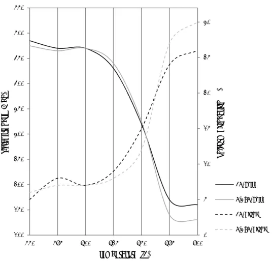
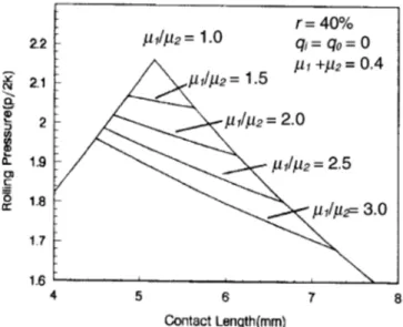
Figure 2.16: the specific rolling pressure distributions for different friction factors [Gao 2002]. .... 35
Figure 2.17: variation of rolling torque with change in friction coefficient ratio [Gao 2002]: a) the roll with higher friction coefficient and b) the roll with lower friction coefficient ... 36
Figure 2.18: slip systems in FCC and BCC materials ... 38
Figure 2.19: macroscopic slip in a single crystal ... 38
Figure 2.20: geometrical relationships between the tensile axis, slip plane and slip direction ... 39
Figure 2.21: the Euler angles φ1, Ф and φ2 describing the rotation between the sample and macroscopic axis ... 41
Figure 2.22: three dimensional orientation space of Euler angles ... 42
Figure 2.23: orientation of (0001) plane in a hexagonal crystal described by the two angles α and β44 Figure 2.24: the 3-D and 2-D ODF presentation [www] ... 44
Figure 2.25: the texture components of FCC material: a) φ2= 0 and b) φ2=45° ... 46
Figure 2.26: rolling texture {111} pole figure of a) pure copper and b) brass... 46
Figure 2.27: α and β fibres in Euler space ... 47
Figure 2.28: fiber texture in a BCC material; φ2=45° [Lee 2001] ... 48
Figure 2.29: important texture of BCC material a) ODF in φ2=45° and b) {200} pole figure ... 49
Figure 2.30: evolution of the rolling texture: a) α and b) ϒ of low-carbon steel of different total deformations [Holscher 1991] ... 49
Figure 2.31: the variation of the volume fraction of BCC texture with annealing time [Kang 2007]50 Figure 2.32: schematic representation of grain subdivision through plastic deformation ... 56
Figure 2.34: deep drawn cups, a) with earing, and b) without earing ... 59
Figure 2.35: influence of strain path on the forming limit diagram ... 62
Figure 2.36: TEM image and diffraction pattern of 90% ASR aluminium; a) as rolled, b) after annealing at 150°C for one hour [Jiang 2009] ... 63
Figure 2.37: grain maps from EBSD of low carbon steel: a) ASR deformed and heat treated at b) 400, c) 500 and d) 600 °C [Ding 2009]... 64
Figure 2.38: TEM image of a ASR steel sheet [Ding 2009] ... 64
Figure 2.38: EBSD cartographies showing microstructures of TD planes after: a) 32.2% reduction for 1.1 roll speed ratio and b) 36.8% reduction for 1.45 roll speed ratio [Wautheir 2009]... 65
Figure 2.39: {111} pole figure of aluminium after 93% total reduction with ASR: a) 10% b) 20% and c) 30% reduction per pass [Lee 2002] ... 65
Figure 2.40: φ2=45° ODF section of asymmetrically rolled aluminum alloy sheet [Sidor 2008] ... 66
Figure 2.41: φ2=45° ODF section of IF steel: a) initial, b) C-ASR and c) R-ASR processes [Toth 2012] ... 66
Figure 2.42: orientation density along α and ϒ fibres in deformed non-orientated silicon steel material with CR, ASR processes [Sha 2008] ... 67
Figure 3.1: some examples of deep drawn pieces produced from aluminium alloy sheets ... 72
Figure 3.2: tensile test machine _ University of Aveiro ... 73
Figure 3.3: uniaxial tensile test results of the AA-5182 in RD, 45° from RD and TD directions .... 73
Figure 3.4: the serration appeared during uniaxial tension in AA-5182 ... 74
Figure 3.5: R-value in various directions from RD... 75
Figure 3.6: X-ray diffraction device and a texture goniometer _ University of Aveiro ... 75
Figure 3.7: X-ray polefigures and ODF (φ2=0 and 45°) of received AA-5182 sample ... 76
Figure 3.9: X-ray pole figures and ODF (φ2=0 and 45°) of the rolled and annealed AA-5182 ... 78
Figure 3.10: influence of annealing temperature (for 45 minutes) on the yield strength and uniform elongation obtained by uniaxial tensile tests in RD of CR, C-ASR and R-ASR deformed samples 79 Figure 3.11: stress-strain curve of CR and annealed sample and also the fitted curve using Voce law parameters ... 81 Figure 3.12: some examples of IF steel applications in automotive industries ... 82 Figure 3.13: stress-strain curves of initial sample in various directions from RD ... 83 Figure 3.14: R-value in various directions from RD... 83 Figure 3.15: optical microstructure of received IF stee1 sheet from a) TD and b) ND planes ... 84 Figure 3.16: thermal stability of ASR sample: influence of annealing temperature on the yield stress and uniform elongation of the IF steel sheets ... 86 Figure 3.17: influence of annealing temperature on microstructure of IF steel sheets: a)550, b)600, c) 650 and d) 700°C for one hour ... 87 Figure 3.18: the first and second pass of various strain routes: a) CR, b) R-ASR and c) C-ASR processes ... 88 Figure 4.1: scratched line on the side face of the samples after: a) first pass ASR, b) second pass of C-ASR and c) second pass of R-ASR ... 93 Figure 4.2: texture of CR (50% reduction); a) experimental and b) predicted by VPSC model ... 94 Figure 4.3: crystallographic texture of one pass of ASR (28% reduction): a) experimental, b) predicted by VPSC model ... 95 Figure 4.4: C-ASR: a) experimental, b) simulation ... 96 Figure 4.5: R-ASR: a) experimental, b) simulation ... 97 Figure 4.6: the experimental and simulated (VPSC approach) stress-strain curves of R-ASR, C-ASR and CR samples in RD ... 98
Figure 4.7: the variation of R-value in different directions from the RD, a) recrystallized, b) CR, c) C-ASR and d) R-ASR samples ... 100 Figure 4.8: VPSC simulation of uniaxial tension in RD of individual texture components ... 102 Figure 4.9: R-value simulation (VPSC) of recrystallization components in different direction from the RD ... 103 Figure 4.10: R-value simulation (VPSC) of a) rolling and b) shear texture components in different direction from the RD ... 104 Figure 4.11: φ2=45° section of ODF of the samples deformed 60% with a) CR and b) C-ASR .... 106
Figure 4.12: optical microscopical observation of TD plane of the samples rolled for 18% reduction with a) C-ASR, b) CR, and 60% reduction with c) C-ASR and d) CR ... 107 Figure 4.13: AFM observation of TD plane of the samples rolled for 18% reduction with a) C-ASR, b) CR, and 60% reduction with c) C-ASR and d) CR ... 107 Figure 4.14: TEM observation of ND plane of the sample rolled for 18% reduction with C-ASR process ... 108 Figure 4.15: TEM observation of ND plane of the sample rolled for 18% reduction with CR process108 Figure 4.16: TEM observation of ND plane of the sample rolled for 60% reduction with C-ASR process ... 109 Figure 4.17: TEM observation of ND plane of the sample rolled for 60% reduction with CR process110 Figure 4.18: TEM observation of ND plane of the sample rolled for 60% reduction with R-ASR process ... 111 Figure 4.19: true stress-strain curves of asymmetric rolled samples under different strain paths .. 112 Figure 4.20: α parameter of sequence of strain paths: C-ASR (different ԑ ) and uniaxial tension ... 113 Figure 4.21: true stress-strain curves of uniaxial tensile test in RD ... 114 Figure 4.22: true stress- strain curves of CR and C-ASR samples after annealing ... 115
Figure 4.23: simulation (VPSC approach) of the mechancial behaviour of individual texture components (BCC) through tension in RD ... 117
List of tables
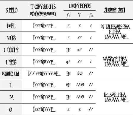
Table 2.1: the texture components of FCC material ... 45 Table 2.2: list of texture components and fibres of BCC materials ... 48 Table 3.1: chemical composition of AA-5182 ... 72 Table 3.2: chemical composition of received IF steel ... 82 Table 4.1: normal and planar anisotropy of CR, C-ASR and R-ASR samples ... 101 Table 4.2: R-value in RD of different reductions of CR and C-ASR ... 116
chapter 1- introduction
13
Chapter 1
asymmetric rolling of AA-5182 and IF steel sheets
chapter 1- introduction
15 Nowadays, automotive, aerospace, structural and food packaging industries are the main fields of metal forming industries. Generally with a view to meeting environmental and economic concerns, engineers and manufacturers need to design lighter and safer products, and also with more complex shapes. This requires producing materials with extra ordinary properties.
About 90% of all metal production starts off as cast. However, a very large proportion of this is then processed by metal forming processes, either to improve the structure and properties and/or to give the desired final shape (or close to that) required. The rolling process can be regarded as the principal metal forming process, in which the metallic sheets are compressed and squeezed by working-rolls. Currently, millions of tons of rolled steel and aluminium alloys are produced annually in the world. Hence this is a field of manufacturing where improving mechanical properties through optimizing the parameters could translate into considerable economic benefits.
The rolling process often introduces anisotropy to metallic sheets. Anisotropy is the state of a material possessing properties depending on directionality of the material. Anisotropic mechanical behaviour of rolled materials which are associated with the texture developed in the rolling process is not desirable for some applications such as deep drawing industries. This results in thinning and earing problems during the process. The asymmetric rolling process, as a derivation of the rolling process, seems to have the potential to develop appropriate textures in metallic sheets to solve these problems. Furthermore in the literature it has been shown that the asymmetric rolling process is capable of refining the microstructure and changing its morphology. The prominent factor of asymmetric rolling which distinguishes it from the rolling process is its potential to distribute uniform shear
asymmetric rolling of AA-5182 and IF steel sheets
16
deformation throughout the sample thickness. This shear strain promotes the development of shear texture and microstructure refinement.
The main objective of this thesis is to study the effect of asymmetric rolling on the mechanical behaviours of aluminium alloys and steel sheets and evaluate the impact of shear deformation on texture evolution and microstructure changes. The study of the influence of shear deformation imposed by asymmetric rolling on samples with two different crystallographic structures (i.e. face centre cubic of aluminium alloy and body centre cubic of IF steel) may give us a more comprehensive view of this process which makes it possible to improve the mechanical properties of the materials.
The current thesis is structured into four chapters, the introduction being the first. Subsequently, the asymmetric rolling process as a severe plastic deformation method is presented in the second chapter. Additionally, the basic concepts of plastic deformation mechanisms of cubic materials are discussed. Furthermore, the main crystal plasticity theories including their benefits and deficiencies are briefly introduced. Chapter 3 deals with the materials observed in this work and also experimental methodologies. In addition to characterizing the received materials, preliminary results are presented in this chapter. Chapter 4 is dedicated to the results and discussion of both materials in the process. A list of conclusions is also given chapter 5.
chapter 2- bibliography review
17
Chapter 2
Bibliography review
asymmetric rolling of AA-5182 and IF steel sheets
chapter 2- bibliography review
19 In this chapter, a general introduction to sheet metal forming is provided, with a focus on microstructure and crystallographic texture evolution during plastic deformation. Additionally, the asymmetric rolling (ASR) process as a new severe plastic deformation (SPD) method is introduced. It is shown that shear strain is a significant feature of SPD processes. Likewise the impact of shear deformation provided by ASR on microstructure and crystallographic texture is discussed. Due to the great practical interest in a deformation polycrystalline theory, a large number of studies have been devoted to various theories. In this chapter, a short review of crystal plasticity models that have been used to predict texture evolution and its resulting mechanical responses is presented.
2-1 severe plastic deformation techniques
Materials processing by severe plastic deformation (SPD) have been under intense focus in the research community the last decade due to the unique mechanical properties obtainable by SPD processing. The process of SPD is based on intense plastic deformation of a work-piece, resulting in alteration of the microstructure and texture. Thanks to these new techniques, a new horizon has opened for processing metallic materials.
Several SPD processes have been proposed in order to optimize the microstructure and crystallographic texture and present better mechanical properties, such as equal channel angular pressing and accumulative roll bonding. Also, some other developed techniques which originated from ECAP are suggested.
2-1-1 traditional SPD processes
Equal channel angular pressing: The equal channel angular pressing (ECAP) process
asymme
20 applied 2001]. T well lub plunger will mo sample techniqu high lev The die intersec intersec during structur changin As men crossing texture plastic s obtaineetric rolling o
to the samp The ECAP bricated spe r then press ove as a rig at the cross ue. In the p vel of plasti e geometry ction betwe ction). Thes the process re and also ng the samp ntioned abo g plane of in the pro strain in the d by ECAPof AA-5182 a
ple through tool is a di ecimen of th ses it into th gid body, a sing plane o presence of a ic deformati Figure 2 is defined en the two se paramet s. The shea developing ple direction ove, the de the chann ocessed sam e ECAP pro P is similarand IF steel s
h an angle in ie with two he same cro he second c nd deforma of the chann a hydrostati ion, specim 2.1: schemati d by the cro channels) ers determ ar strain wh g the textur n after each formation i els. This c mple. Toth ocess and th r to that obsheets
n the ECAP intersecting oss-section i channel. Un ation is ach nels. Fig. 2. ic compress en fracture c sketch of th oss section and ψ (the ine the she hich is the re can be m pass of ECA in ECAP is circumstance et al. show he simple sh btained duri P die while r g channels is placed int nder these hieved ideal 1 illustrates sive stress f does not oc he ECAP tech n area and arc of cur ear strain i responsible modified by AP [Iwahas s mainly a e leads to wed the simhear test. Th ing the shea
retaining its of identical to one of th circumstanc lly by a sim s the princip field in ECA ccur. hnique the angles rvature at th introduced e for formi y repeating shi 1998]. simple she form the s milarity bet hey reporte ar test [Tot s dimension l cross-secti he channels, ces the spe mple shear ple for the E AP, in spite
Ф (the ang he outer po
into the s ing the ultr the proces ear acting shear comp tween intro ed that the te th 2004]. S n [Kim ion. A and a cimen in the ECAP of the gle of oint of ample ra-fine ss and at the ponent oduced exture imilar
results Jining deforma of sub g pressing microst bands o It is tho sample disadva develop [Saito 2 illustrat Accum process workers in a sim samples between contact. bonds b were also 2004]. The ation in the grains. The gs into hig tructure. In of elongated ought that th is still sm antages of E ping ECAP 2000] and eq tes the Cons
Figure 2.2 mulative rol s which prod s developed mple rollin s are carefu n the sheet . Subsequen between the observed b e initial m first pass th se sub-boun gh-angle gr other word d sub-grains he ECAP ca mall. From ECAP is tha to a contin qual channe shearing and 2: schematic s ll bonding duces the ul d the ARB p ng process fully degrea t pieces. Tw ntly, rolling sheet speci by other stu massive red hrough the ndaries sub rain bound ds, one pass s and further an certainly a viewpoi at it is not a nuous proce el angular ro d ECAR pro sketches of a) : Accumul ltra-fine gra process for [Saito 199 ased and w wo sheets w g of 50% red imens. For t udies [e.g. duction in die because sequently e daries, ultim of ECAP r r pressing le fabricate bu int of prac a continuou ess have be olling (ECA ocesses. ) the Conshea lative roll b ain (UFG) s
the first tim 8]. In this wire brushed were stacke duction was the second p Werenskio grain size e the origina evolve with mately givi results in a eads to form ulk materia ctical applic s process b een done, li AR) [Lee 20 aring and b) bonding (A structure in me in which technique, d in order ed such tha s conducted pass of the
chapter 2- b
ld 2005, S is achiev al grains bre more shear ing a reas microstruct m arrays of e als, but the tcation, one ut a batch p ike the Con 002a]. Fig. 2 the ECAR te ARB) is a sheet samp h SPD strat the surfac to form ap at brushed which lead process, the
bibliography r
krozki 200 ed during eak up into r strain in f onable equ ture consist equiaxed gr typical size e of the gr process; tria nshearing pr 2.2 schemat echnique continuous les. Saito an tegies are ap ces of two ppropriate surfaces w ds to formin e rolled samreview
21 8 and shear bands further uiaxed ting of rains. of the reatest als for rocess tically s SPD nd co-pplied sheet bonds ere in ng new mple isasymme
22 cut and several Since t deforma Subsequ procedu layers b proceed of the s sample cycles oetric rolling o
d stacked w times. The the ARB p ation is int uently, half ure is repea but are com ds. Lee et al sample in th after the fir on the basisof AA-5182 a
with a treatm principal of Figure process is troduced in f of the su ated. As a r mplexly distr l. [Lee 2002 he ARB pro rst pass and of the meaand IF steel s
ment describ f ARB is sc 2.3: schemat carried ou n the surfa urface regio esult, the sh ributed thro 2b] obtained ocess. He m d then predic asurement (Fsheets
bed for the chematically ic sketch of t ut without ce regions ns come to heared regi ough the thi d the distrib measured the
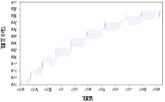
cted the she Fig. 2.4). e first pass. y illustrated he ARB tech lubrication, in every s o the centre ons do not ickness of t bution of sh e shear stra ear strain di This proce d in Fig. 2.3 nique , a large a single pass e in the ne localize on the sheets a ear strain fr ain from the istribution a edure is rep . amount of s of the pr ext pass an nly on subsu as the ARB rom the thic e thickness after several peated shear rocess. nd this urface cycle ckness of the l ARB
Figu A simi Kamika and cry produce factor w cold-rol formati rolling thickne fast form ure 2.4: the di lar distribu ava 2007]. L ystallograph ed shear str which distin lling may l on of the ul with the sa ss of the sh ming the UF istribution of processed ution has a Like other S hic texture o rain throug nguishes th lead to pro ltrafine stru ame total de heet introdu FG structur f shear deform d by a) 1, b) 2 lso been re SPD techniq of the sampl hout the th he ARB pro onounced u cture during eformation uced during re. mation throu 2, c) 4 and d) eported in ques, the A les. The am hickness of ocess from ultrafine stru g the ARB p [Yan 2011] this proces ugh thickness 8 cycles [Lee the previou ARB process mount of tota the sheet d cold-rollin uctures in process is m ]; i.e. the di s, presented
chapter 2- b
of the sampl e 2002b] us works [ s changes th al strain is i during the ng. Studies metallic m much faster istributed sh d in Fig. 2.4bibliography r
le severely AR [Costa 200 he microstru important b process is show that materials. Bu than that in hear strain 4, is the caureview
23 RB 5 and ucture but the a key heavy ut the n cold-in the use forasymme
24 In term that the and sur the text because surface accumu texture the shar destroy Other product which c leads to pressing 2005]. Repetiti the rep 2001]. mode. Tetric rolling o
ms of crystal e samples d rface region ture in the t e of severe p has been ulated, this in the surfa rp shear tex ed by the su techniques tion of bulk contains a g o developing g is not a co ive corruga etition of b This techni The schemaof AA-5182 a
llographic o deformed by ns. Despite thickness ce plastic defo surface thr area presen ace is expec xture devel ubsequent ro s: Recently ky UFG m grooving and g a shear de ontinuous pr Figure 2 ation and str bending and ique seems atic sketch oand IF steel s
orientation e y this techn of shear tex entre seems ormation ap roughout th nts the max cted. But th loped by se olling (plan y, new SPD materials has d a flattenin eformation rocess and t 2.5: schemati raightening d bending-b to be conti of the procesheets
evolution du nique posse xture detect s relatively pplied on the he ARB pr ximum shea he texture e evere shear ne-strain) de D processes s been sug ng die (Fig. in the ortho the thicknes ic sketch of th (RCS) pro back witho inuous to th ss is shown uring the A ess large di ted in the s random wh e sample [H rocess and ar strain. C evolution in deformatio eformation i s which se gested. Gro 2.5). The g ogonal plan ss of the she he groove pre cess has be out change he groove p n in Fig. 2.6. ARB process fference be surface regi hich is som Huang 2003 the shear Consequently n the centre on in the pr in the follow eem hopefu oove pressi geometry of ne to the she eet sample i essingeen also car in the sam rocess in te . s, it was rep etween the ions of the mewhat surp 3]. Since the strain has y, a strong area is diff revious pas wing pass. ul for conti ing is intro f the groovin eet plane. G is unaltered rried out wh mple size [H erms of the ported centre sheet, prising e final been shear ferent; sses is inuous oduced ng die Groove d [Park hich is Huang strain
The RC but the depends
2
It has b behavio on sam applicat to solve also sam process modify disturba deforma symmet is provi Fi CS and groo difference s on the toll2-1-2 asym
been shown our. Howev mples with l tions. The m e this deficie mple sizes. R s has been i crystallogr ance of the ation throug try about th ided in Fig. igure 2.6: sch ove pressing e between t ls dimensionmmetric ro
that SPD t ver, a weakn limited dim modified SP ency, but th Recently, th introduced, aphic textur e symmetry gh the meta he centre lin 2.7. hematic sketc g processes them is the ns.lling proc
echniques w ness of thes mensions, w PD techniqu hey still hav he asymmet which is a re with enha y of the co allic sheet, ne of the sh h of the RCS are based e amount oess
were propos se methods which greatl ues presente ve limitation tric rolling ( able to prod anced perfo onventional i.e. the AS eet. The sch S techniques [ on repeatin of plastic d sed in order is still the ly affects t ed in the pre ns such as e (ASR) proc duce ultrafi ormance. Th rolling pro SR is a kind hematic illuchapter 2- b
[Huang 2001] ng the bendi deformation r to improv fact that th their potent evious secti xtra ordinar ess, a novel ine grain m he principal ocess which d of rolling ustration ofbibliography r
] ing in the p n per pass w ve the mech ey are cond tial for indu ion were attry equipmen l continuou materials and base of AS h causes a g process w the ASR pr
review
25 passes, which hanical ducted ustrial tempts nt and s SPD d also SR is a shear ith no rocessasymme
26 Figure In this p the wor conditio an extra grain ro forming amount Those k working rotation K.H.Kim rolls dia In addit rotation samples Fig. 2.8 velocity the stee (a)etric rolling o
e 2.7: the sche process, the rk-roll and ons on the s a shear strai otation duri g desirable t of shear str kinds of AS g-rolls are d n speed or v m and D.N ameters are tion, Jin an n speeds of s. 8 shows the y ratio durin el sheet [Lof AA-5182 a
ematics of asy diameter e symmetry lower one; sheet faces. in in additio ing deforma textures. Th rain impose SR processe different can varying the .Lee [Kim 2 considered nd Lioyd [J working ro FEM analy ng the ASR Lee 2001].and IF steel s
ymmetric rol r, b) friction c disturbance ; such as ei Under thes on to compr ation which he level of ed through t es in which n be gained rotation sp 2001a] and d to impose Jin 2005] an olls in order ysis of the in R on the sh The deform (b)sheets
ling processe conditions an e is due to t ither circum se circumsta ression defo h is respons symmetry the thicknes h the circum d by either v eed of rolls also S.H.K shear strain nd F.Simoe r to achieve nfluence of hear deform med meshe es using differ nd c) rotation the variance mferential v ances, the m ormation. T sible for gr disturbance ss of the sam mferential ve varying the d s of the sam Kim et al. [K n through th es et al. [Sim e the desira f difference mation distri es indicate rent methods n speeds e of roll par velocities of metallic she This extra sh rain refinem e of the AS mple. elocities of diameter of me diameter Kim 2002] d he aluminiu moes 2008] able shear s in roll diam ibution thro that the sh (c) s: a) working-rameters in f rolls or fr eet is subjec hear strain c ment and al R determin f upper and f rolls at the r. In the wo different wor um sheet sam ] applied v train in the meter and ro ough thickn hear deform -rolls upper riction cted to causes so for nes the lower e same orks of rking-mples. arious e sheet otation ness of mationpenetrat that app Figure 2 Usually deforma friction experim the FE m Like the raises th shear st between applied shear st
tes into the plying a sing 2.8: FEM cal y in ASR ation in the s of two sur mentally obs method by J e other type he idea that train throug n the passes complex s train throug e centre with gle roll driv
culation of de at r technique, e metallic sh rfaces are n served by U Ji and Park es of SPD te t rotating th ghout the th s through A train paths hout thickn h change in ve results in eformed steel oll rotation s a high v heet Nevert not equal. T Utsunomiya [Ji 2009]. echniques, A he sheet sam hickness of t ASR are show
including c ness of the sh n circumfer n a shear dis l sheets with peed ratio of value of fri theless, it ca The roughne et al. [Utsu ASR is base mple betwe the sample. wn in Fig. 2 conventiona heet specim ential veloc tribution th the ASR: a) a f 1.5 [Lee 200 iction is d an still be a ess differenc unomiya 20 ed on repeat een the pass The possib 2.9 [Lee 200 al rolling an men [Sidor 2
chapter 2- b
cities. This rough the th at roll radius 01] demanded t a factor of th ce of two sh 007] and als ting of diffe ses leads to ble routs of 01]. Further nd ASR in 2008].bibliography r
work also s hickness. s ratio of 1.5 a to impose his process heet surface so analysed erent passes o imposing f sample rot rmore Sidor order to proreview
27 shows and b) shear if the es was using s. This larger tations r et al. omoteasymme
282-2
Rolling rolls rot primary materia2
Since in much s (Fig. 2.etric rolling o
Figursheet roll
g is a metal tating in op y objectives al while imp2-2-1 basic
n sheet roll maller than 10).of AA-5182 a
re 2.9: possiblling
forming op posite direc of the flat r proving its pc concepts
ling, the len n the width
and IF steel s
le sample rot peration in w ctions in ord rolling proc properties.of conven
ngth of con of the shesheets
tations betwee which meta der to reduc cess are to rntional and
ntact betwe eet, w, it is en the ASR p al is passed ce the initial reduce the cd asymmet
een rolls an essentially passes [Lee 20 between a l thickness ross-sectiontric rolling
nd work pie a plane str 001] set of cylin of the meta n of the incog
ece, L, is u rain compre ndrical al. The oming usually essionThe pla directio on both Neutra contact materia 2.11. From N between astic zone w on, x. But la h sides of the al point: Th depicted by al and the ro Figure N to the exit n work-pie Figure 2.10: which is thin ateral expan e roll gap ex he rolls mak y an arc (se oll move wi e 2.11: the fric t, the metal ce and roll schematic of nned by the nsion in the xcept at the ke contact w ee Fig. 2.11 ith the same
ction directio moves fast l opposes f the deforma compressiv y-direction e edges whic with the su 1). At a cert e speed wh on on the inle
ter than the motion. Th ation zone in ve stress is n is limited b ch leads to s urface of th tain point o ich is called et and outlet s roll surface he metal m
chapter 2- b
flat rolling free to expa by the unde such a plane e sample o of contact, t d the neutraside of the sam
e. In this re moves slowe
bibliography r
and in the r eforming ma e strain. ver the leng the surface al point N i mple egion, the fr er than thereview
29 rolling aterial gth of of the in Fig. riction e rollsasymme
30 between the proc position diamete tensions increase There e in conta ideal co asymme previou the sam values b roll sur rolling, lower r differen lower ro F Figure 2 rolling p and foretric rolling o
n N and the cess. This f n of neutra ers of the ro s to the she es. exists the A act with the onventional etric rolling us section (§ mple speed between the rface speed the horizon roll. But in nt, the locat oll (Fig. 2.1 Figure 2.12: s 2.12 also sh processes. I rward-slip zof AA-5182 a
e inlet point. friction forc al point in olls and the eet. The neu’B’ arc with e second wo l rolling in g which the § 2-1-2). In increased f ese entry an are equal ntal position asymmetri tion of the 12b). schematic illu
hows the pla In conventio zones accor
and IF steel s
. The frictio ce over the the contac coefficient utral point t h the N’ po ork-roll (Fig n which ass e symmetry the rolling from inlet t nd exit spee we have a n of the neu ic rolling, s neutral poi ustrations of astic deform onal rolling rding to thesheets
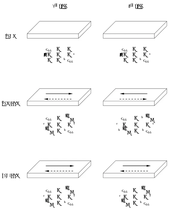
on in this pa contact arc ct arc depe of friction a tends to mo int as a neu g. 2.12). It c sumes sym y of the pro process, th to outlet an eds. As men neutral po utral point o since the sp int of the u a) convention mation regio g the region e friction di art acts in th c draws the ends on the and also on ve to outlet utral point o can be discu mmetry abou ocess is dis he thickness nd roll spee ntioned abo oint. Due to on the uppe peeds of th upper roll i nal rolling an ons in two c at the roll g irections ex he direction metal into e amount o n applying th t as the amo on the other ussed in tw ut the strip sturbed as m s of the she eds have so ove, where o symmetry er roll is equ he upper an is different nd b) asymme conventiona gap is divid xerted on th of rolling, a the roll gap of reduction he front and ount of redu r face of the wo different p centre-lin mentioned et is reduce ome interm the sheet an y in conven ual to that o nd lower ro from that etric rolling al and asymm ed into back he sheet fro aiding p. The n, the d back uction e sheet ways; ne and in the ed and mediate nd the ntional on the oll are of the metric kward om thechapter 2- bibliography review
31 work-rolls. In asymmetric rolling a third cross shear deformation zone is formed between the backward-slip zone and the forward-slip zone. Both compressive and shear stresses occur simultaneously in the cross shear deformation zone.
2-2-2 forces and torque
The rolling power is applied to a rolling mill by applying a torque to the rolls. This power is expended principally in different ways; the necessary energy for deforming the specimen and the necessary energy to overcome frictional forces. The rolling load is distributed over the arc of contact in the typical friction hill pressure distribution which describes the profile of the rolling pressure across the contact arc. Numerous works have been carried out developing the analysis of treatments of rolling. Slab method, slip line field theory and finite element method are the main theoretical methods to attain rolling force and rolling torque. Slab method is the simplest method which is aimed at expressing the rolling force and rolling torque in terms of geometry of the deformation and the strength properties of the material. In this method, a differentially thick slab of the material is selected perpendicular to the rolling direction in the deformation region. Force balance for the slab results in a differential equation, which is solved either by close form analytical methods or numerical methods. The constants of integration are obtained by applying the appropriate boundary conditions [e.g. Dieter 1988 and Hosford 1993]. In the following section the rolling force and torque in both conventional and asymmetric rolling processes will be analysed.
The assumptions for slab analysis of rolling pressure and torque are: ‐ The rolls are rigid
‐ The material is elastic-plastic
‐ There is no width expansion during the process- plane strain condition ‐ The stresses are uniform in the contact area
‐ The friction conditions are uniform along the contact length, although the upper and lower coefficient friction can be different (in the ASR process).
‐ The plastic flow at the entrance and exit are assumed to be horizontal. ‐ The principal axes are in the directions of the applied loads.
asymme
32 In the rolling the cont is the pr Where effects conditio 1993]: where h between initial s resistan of roll p and then The are calculatetric rolling o
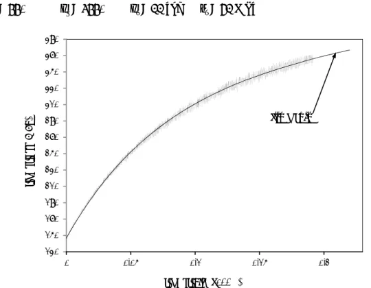
conventiona geometrica tact area (L rojected are √ ∆ Δh and R a are similar on in the sh h and μ ar n the surfac sheet sample nce of the sh pressure alo n falls off. Figure ea under t tion acts atof AA-5182 a
al sheet rol al parameter L). The press ea of the arcare the thick r to those in eet rolling p 1 re the thick ces respecti e becomes t heet is grea ong the cont
e 2.13: distrib the curve i the centre o
and IF steel s
lling proce rs. The rolli sure is the y c of the cont kness reduc n plane stra process, the kness of th ively. The thinner. Ev ater than thetact. The ro bution of roll is proportio of gravity o
sheets
ss the rolli ing load, P, yield stress tact of sheet ction and th ain compre e pressure, P he sample a equation sh entually, a e roll pressu oll pressure pressure alo onal to the of the pressu ng loads ar , is given b of the mate t in the rolli he roll radiu ession. As c Pav, has beenand the ave hows that r
point is rea ure. Figure
rises to a m
ong the contac
e rolling lo ure distribut re derived by the roll p erial, σ0, and ing gap: (2.1) us respectiv concerns to n derived as (2.2) erage of fri rolling load ached where 2.13 depict maximum at ct [Hosford 1 oad which tion. Theref as a functi pressure, p, d the contac ely. The fr o the plane s below [Ho iction coeff d increases e the deform ts the distrib t the neutral 1993] for purpos fore, the sha
ion of times ct area riction strain osford ficient as the mation bution l point ses of ape of
the pres the roll Since th area, th Fig. 2.1 In the a there ar should b each de RD ssure distrib centre dete he neutral p he pressure 14). Figur asymmetric re three def be analysed eformation z bution is imp ermines the t point in the distribution re 2.14: distri rolling pro formation r d separately zone [Yong Figure 2.1 portant bec torque and rolling pro n does not p ibution of rol ocess due to regions in t y. Figure 2.1 2009]. 15: slab eleme
ause the loc the power r ocess is not present a sh ll pressure alo o the positi the asymme 15 illustrate ent of differen cation of the required to p really a lin harp maxim
ong the conta
ions of upp etric rolling s the stress nt deformatio
chapter 2- b
e rolling loa produce the ne on the ro mum at the n act [Dieter 19 er and lowe g process ( states of th on zonesbibliography r
ad with resp e reduction. oll surface b neutral poin 988] er neutral p Fig. 2.12) w he slab elemreview
33 pect to but an nt (see points, which ment inasymmetric rolling of AA-5182 and IF steel sheets
34
The balance of forces along x and y directions in three different zones and the boundary conditions make it possible to describe the roll pressure p when the sheet passes through the roll gap. Here, q0 is the front-tension force and qi is the back-tension force. Using
equilibrium conditions of the deformation zones and also with the Von Mises yielding criterion:
2 (2.3),
where k is the yield strength in shear. The general equation of rolling pressure equation was obtained by Gao et al. [Gao 2002]:
̅ ̅ ̅ ̅ ̅ (2.4)
where
̅ , ̅ , ̅
where R is roll mill diameter, μe is the effective friction coefficient and x is the distance
from the vertical line through the centres of the working-rolls. The constant C is related to the boundary condition which can be obtained.
The boundary condition for zone iii: , ̅ 1
2 0 0 And in zone i:
, ̅ 1
2 And in zone ii, shear region:
, ̅ ̅ , ̅ ̅
where xn1 and xn2 arethe positions of neutral points which can be determined using the
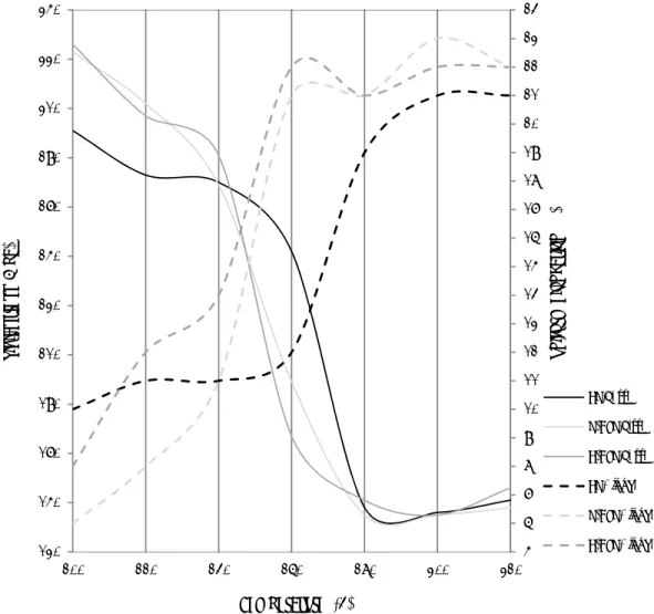
Figure 2 [Gao 20 there is point of in the d length o Figu The sam velociti circumf also the The tota P = pb + The rol mill. Ge integrat 2002]. T1 = μ1 2.16 shows 002]. In the no shear re f the proces deformation of the shear ure 2.16: the me trend ha ies and roll ferential ve e average ro al rolling fo + ps + pf lling torque enerally, th ting the mo R1 (Pb - Ps -the specific e convention egion in the ss. Increasin region that zone increa specific rolli as been dete diameters [ locities of u olling pressu orce is the su e is a param he rolling to oment of th - Pf) c rolling pre nal rolling c deformatio ng the ratio t shows the ases when t ng pressure d ected when [Hwang 199 upper and l ure decrease um of the p meter that d orque of upp he friction s essure distri curve, wher on zone. The results in t shear zone the friction c distributions asymmetric 7, Salimi 20 lower rolls es. ressures in determines per and low
stress along ibutions for re the frictio e peak of th the appearan with the ne coefficient r for different c rolling wa 002 and Yo increases, three differ the energy wer rolls, T1 g the conta
chapter 2- b
r various fri on coefficie he curve ind nce of an ar eutral points ratio goes u t friction facto as due to th ong 2009]. W the shear z rent deforma consumpti 1 and T2, ca act length obibliography r
ction coeffi ent ratio equ dicates the n rea like a p s at the side up. ors [Gao 200 e variance o When the ra zone expand ation zones (2.5) on of the r an be obtain of each roll (2.6)review
35 icients uals 1, neutral plateau s. The 2] of roll atio of ds and : rolling ned by [Gaoasymme
36 T2 = μ2 Figure 2 rolls wi to enhan coeffici Figureetric rolling o
R2 (Pb – Ps – 2.17 illustra ith higher an nce not to r ient. 2.17: variatio with hiof AA-5182 a
– Pf)ates the infl nd lower fri resist rolling on of rolling t igher friction
and IF steel s
luence of th iction coeff g. This effec torque with c coefficient asheets
he friction c ficient. In bo ct is even h change in fric and b) the rollcoefficient r oth working higher in the ction coefficie l with lower f ratio on roll g rolls, the f e roll with th
ent ratio [Gao friction coeff (2.7) ling torque friction forc he higher fr o 2002]: a) th ficient in the ce acts riction he roll
chapter 2- bibliography review
37
2-3 slip system: a plastic deformation mechanism
Plastic deformation occurs by sliding of one part of a crystal relative to another along the certain planes. Unlike elastic deformation involving only the stretching of interatomic bonds, slip requires the breaking and re-forming of interatomic bonds and the motion of one plane of atoms relative to another.
In order for plastic deformation to take place, dislocations move through the grains. They do not move with the same degree of ease on all crystallographic planes in all crystallographic directions. Observations show that slip tends to occur preferentially on certain crystal planes and in certain specific crystal directions. These planes are known to the slip planes and the direction of the dislocation movement is called the slip direction. The combination of the slip plane and the slip direction is termed the slip system. The slip system depends on the crystal structure and is such that the atomic distortion that accompanies the motion of a dislocation is minimal. Usually in the crystals, slip plane is the plane with the most dense atomic packing. The slip direction corresponds to the direction in this plane that is the most closely packed with atoms. As shown in Fig. 2.18 the dominant slip systems vary with the material’s crystal lattice. In the case of face centre cubic (FCC) crystals, slip occurs mostly on {111} octahedral planes and in <110> directions which are parallel to cube face diagonals. In all, there are 12 such slip systems (four unique {111} planes, and within each plane three independent <110> directions) [Kocks 1998]. In body centre cubic (BCC) crystals, slip occurs in the <111> cube diagonal direction and on {110} dodecahedral planes. In this structure, dislocations also slip on other planes such as {112} and {123} under various conditions, and sometimes the behaviour can be adequately described by pencil glide with a <111>slip direction. There are 48 possible slip systems, which are the combinations of these three planes and pencil glide direction [Kocks 1998].
asymme
38 Plastic a slip pl the shea can ofte As can formati loop aroetric rolling o
slip is a she lane and alo ar compone en be assumbe seen in on of small ound its circ
of AA-5182 a
Figure 2 earing proce ong a slip d ent exists to med not to in n Fig. 2.19 l steps on t cumference Figurand IF steel s
2.18: slip syst ess; disloca direction. Ev force disloc nfluence slip the movem he surface e. re 2.19: macrosheets
ems in FCC a tions move ven though cations mov p. ment of disl of the samp oscopic slip in and BCC ma in response an applied ving in the s locations in ple that aren a single cry aterials e to shear st stress may slip plane. H n the slip p e parallel to ystal tresses appl be purely te Hydrostatic lane leads one anothe lied in ensile, stress to the er and
2
Assumi 2.20 ϕ directio is loade directio the slip stress o τ = σ co where c respons resolved [e.g. He crystal, system availabl of the s Fi2-3-1 Plast
ing that a si represents on; and λ inded with ten on is τ. As s p direction i n the slip pl osλ cosϕ cosλcosϕ re se to the ap d shear stre ertzberg 19 each of the possessing le, the nece lip systems igure 2.20: ge
tic deform
ingle crysta the angle b dicates the a nsile stress shown in Fi is A.σ.cosλ lane and in epresents an pplied stres ess reaches 937 and Cal em having a the greates ssary load f . eometrical relmation of si
al in the sha between the angle betwe σ, the shea ig. 2.20, if λ, which ac the slip diren orientation ss, slip in a critical v lister 1999] a different S st Schmid’s for yielding lationships b
ingle cryst
ape of a rod e normal to een the slip ar stress ac the cross se ts on slip a ection is: n factor (oft the mentio alue, terme ]. There are Schmid’s fac s factor. Co g can vary d etween the tetals
d is tested i o the slip p and stress d cting on the ection area area A/cosφ ten referred oned slip sy d the critic e a number ctor. The yi onsequently dramaticallyensile axis, sli
chapter 2- b
in tension; plane and th directions. W e slip plane of sample i φ. Hence th d to as the S ystem will al resolved r of slip sys ielding will y, if only a y with the re ip plane andbibliography r
as shown i he applied When the s e and in th is A, the fo he resolved (2.8) Schmid facto occur whe shear stres stems in a occur on th few system elative orien slip directionreview
39 n Fig. stress ample he slip orce in shear or). In en the s, τcrss single he slip ms are ntation nasymmetric rolling of AA-5182 and IF steel sheets
40
2-3-2 plastic deformation of polycrystals
Since polycrystal materials are formed of a significant number of crystals with different orientations, plastic deformation of these materials is quite complex. Due to the random orientation of grains, the direction of dislocation slip varies from one grain to another. With the purpose of studying the plastic deformation of polycrystal materials one needs to know detailed information about crystallographic orientation and dislocation structure of polycrystals.
2-3-2-1 crystallographic orientation
2-3-2-1-1 basic concepts
Generally, the grains of a polycrystal material possess different crystallographic orientation from that of their neighbours. To describe the orientation of a crystal relative to macroscopic reference, one often specifies the Miller indices of two directions: the normal of the plane {hkl}, and a line in it, <uvw>. For instance in the case of sheet rolling, the orientation {hkl}<uvw>, means that a {hkl} plane is parallel to the rolling plane, and a <uvw> direction is parallel to the rolling direction.
In order to introduce an orientation, terms of reference are required, which are called a coordinate system [Kocks 1998 and Bunge 1982]. Two Cartesian systems are necessary:
1. The sample coordinate system S= {s1 s2 s3}: The axes of the sample are chosen
according to important surfaces and directions associated with the external shape of the sample. The sample coordinate systems in sheet metal rolling are the rolling direction (RD); the transverse direction (TD); and the normal direction (ND).
2. The crystal coordinate systems C= {c1 c2 c3}: The axes of the crystal are
specified by the directions in the crystal which usually are adapted to the crystal symmetries. For instance, in cubic crystals, the axes [100], [010] and [001] are usually assumed as the crystal coordinates.
The crystal coordinate system (Cc) can be transformed to the sample coordinate system (Cs)
with the orientation matrix (g) which contains the rotations of the sample coordinates onto the crystal coordinates.
Cc = g . where t and sam coordin follows 1. 2. 3. where φ through Figure 2 The rot as three ɸ Cs the orientati mple axes. nate system s: φ1 about th TD’ and the Ф about the φ2 about ND φ1, Ф and φ h the Euler a 2.21: the Eule ations throu e matrices: 0 1 0 0 ɸ 0 ɸ ion matrix i The Euler onto the c he normal d e rolling dir e axis RD’ ( D’’ (in the n 2 are the Eu angles descr er angles φ1, Ф ugh Euler a 0 0 0 1 0 ɸ ɸ a is a matrix i r angles re rystal coord direction N rection RD (in the new new orienta uler angles ( ribes the rot
Ф and φ2 des ngles about ; and including co fer to three dinate syste ND, transfor into RD’ orientation ation) (Bunge defin tation betwe cribing the ro axis t ND, RD’ a osines of th e rotations em [Bunge rming the tr n) nition). Fig een sample otation betwe and ND’’ c
chapter 2- b
he angles be that transf 1982]. The ransverse d ure 2.21 sho and crystaleen the samp
can be analy
bibliography r
(2.9) etween the c form the s e rotations direction TD ows how ro l axes. le and macro ytically exprreview
41 crystal ample are as D into otation oscopic ressedasymme
42 Matrix matrice g = g Any ori a 3-D f Euler s sample. In the m angles a the max the size reduce t The ori which cetric rolling o
0 g, introduc es: . gФ . g ientation ca frame with space can a . F most genera are defined ximum size e of Euler s the range of ientations o causes themof AA-5182 a
0 0 0 1 ed in equat n be identif the axes φ also be use Figure 2.22: th al case of tr in the rang e of the Eul pace by aff f the angles f all the gra m to possesand IF steel s
tion 2.9, can fied as three , Ф and φ ed to repre hree dimensi riclinic crys e 0° ≤φ1, φ ler angle sp fecting the r s Ф and φ2 ains may be s isotropicsheets
n be obtaine e Euler angl φ (Fig. 2.22 sent the or onal orientat stal symmet φ2 ≤ 360°, an pace. Howev range of the (for instanc e randomly properties. ed by multi les (φ , Ф, φ 2). The resu rientation d tion space of E try and no s nd 0° ≤ Ф ≤ ver, various e angle φ1 ce in cubic c y distributed However, iplication o φ ) represe ulting space distribution Euler angles sample sym ≤ 180°, whic s sample sy and also cr crystals Ф, d in relation the orienta f the three (2.10) ented as a po e which is in a polyc mmetry, the ch in turn d ymmetries r rystal symm φ2=90°). n to the refe ation may te above oint in called crystal Euler defines reduce metries erence end tochapter 2- bibliography review
43 cluster to a greater degree about a particular orientation. This is called preferred orientation, or texture and leads to present directional properties. Preferred orientation forms during deformation and is modified through plastic deformation and heat treatment processes.
2-3-2-1-2 pole figure and ODF
The normal of any plane in a crystal can be indicated as a point on the unit reference sphere which is a sphere with radius 1 notionally residing around the crystal. The first point of the vector coincides with the centre of the sphere, and the second point lies on the surface of the sphere. Here, a similar concept can be used for a crystallographic direction which needs two points for each direction.
The orientation of a single crystal located in the centre of a unit sphere can be obtained if the sphere reference system is set as the macroscopic reference system (RD, TD, and ND). Also, if a polycrystal is located in the centre of the unit sphere, the distribution of orientation of the crystals relatively to the sample reference system can be obtained.
Due to difficulty of representation of a 3-D orientation on the unit sphere and also measuring angular distances between them, a 2-D representation is required. The pole figure which is based on the stereographic projection is a method of 2-D representation. The position of a given pole on the sphere is commonly characterized in terms of two angles (Hansen 1978): The angle α describes the azimuth of the pole, where α = 0° is the north pole of the unit sphere, and the angle β characterizes the rotation of the pole around the polar axis, starting from a specified reference direction (Fig. 2.23).
As mentioned above, in order to characterize the crystallographic orientation of a crystal, the spatial arrangement of the corresponding poles in terms of the angles α and β has to be determined with respect to the sample coordinate system S. In a sheet rolling study, the rolling direction RD is usually chosen to be the north-pole and the rotation angle β is 0° for the transverse direction TD.

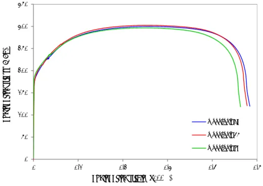
![Figure 2.43: orienta ation density aalong α and γ with CR, AS γ fibres in defSR processes formed non-o[Sha 2008] chapter 2- borientated sil bibliography ricon steel ma review 67 aterial](https://thumb-eu.123doks.com/thumbv2/123dok_br/15814246.1080878/81.918.160.725.124.453/figure-orienta-density-processes-chapter-borientated-bibliography-aterial.webp)