M
ODELLING OF A PROSTHETIC HAND FEATURING INDIVIDUAL GRIP ON EACH ONE OF THE FIVE FINGERSJoana Rosa1, Joana Sousa1 and R. Baptista1
1Escola Superior de Tecnologia de Setúbal, Instituto Politécnico de Setúbal, Campus do IPS; [email protected]
KEYWORDS: Biomechanics; prosthetic hand; 3D Modelling; operational simulation, palmar grip; digital grip
ABSTRACT: The aim of this work is to develop a prosthetic hand with individual grip
functionality on each finger, reproducing the natural movement of the hand. After the preparation of sketches and creating a virtual model, the final model shows dimensions: 124,04 mm × 246,57 mm × 38 mm (palm-covered) and an estimated weight of 1 kg, with all components. Afterwards was executed the functioning simulation of the prosthetic hand, elaborated prehension experiments were made using a metal cylinder, a rubber ball and a wooden pencil, with the tool Motion Study from Solidworks. However in the tests with the pencil was difficult to reach equilibrium, tells us that the hand is not functional with width smaller objects, because they require a bigger finger precision. Was made the study of forces applied in links thinner in different prehensions using the Finite Element Method. This study concluded that the aluminum alloy 2024 T3 has enough resistance to the stresses incurred for the grasping. Finally, was made an estimate cost of production for a single working prototype prosthetic hand. The result was 1325€.
1
I
NTRODUCTIONSocially, the normal body image, without physical defects and deformities has great importance. These values increase social stigma and discrimination towards individuals who have some type of physical disability, such as amputees [1].
In society, there are several areas of science that invest in improving the life quality of these people, mainly through projects that allow the necessary skills to be included in several social and cultural activities. This will promote the reduction of socialization negative experiences. In this particular context we intend to give a greater relief to prosthetic hands. Currently there are several devices on the market, however, many available prosthetic hands present an appearance very different of human hand, unnatural movements caused by the limited DOF (degree of freedom), a low functionality and heavy weight. Therefore,
it is essential that arise in the market new designs, materials and technologies for the benefit of amputees [2].
In this paper, the development of a prosthetic hand design, with individual grip functionality on each finger, reproducing the natural movement of the hand, is described.
2
T
HEH
UMANH
AND2.1 A
NATOMY ANDB
IOMECHANICSThe human hand is composed by 27 bones divided into three main segments: the carpus, metacarpus and fingers [3]. The fingers of the human hand consist of three intercalated bony segments: the proximal, middle, and the distal phalanges. Each finger presents four DOF.
However, the thumb is different, containing only two intercalated bony segments: the proximal, the distal phalanges and presents five DOF (fig.1) [4].
Fig. 1 Anatomy of the Human Hand [5].
2.2 DIMENSIONS
The anthropometric dimensions of the hand with percentile 95, male, age of 40 years and American are 20.6 cm in length, 9.6 cm in breadth and 23.4 cm in circumference. The anthropometric dimensions for the same characteristics but female gender are 18.7 cm in length, 8.6 cm in breadth and 19.3 cm in circumference. [6]
3
D
ESIGNM
ETHODOLOGY3.1
D
ESIGNP
ARAMETERSThe design parameters were chosen consulting bibliographic research of current and future projects of prosthetic hands, based on the intended purpose for this project. Following is a list of the eleven main design parameters that were chosen for use in the design process:
1. The fingers should adapt to the shape of the object;
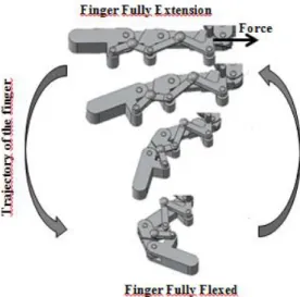
2. The trajectory of the finger and its phalanges should be similar to a normal finger;
3. The hand grip should provide each individual finger;
4. The hand must be able to produce different types of grip, through movements of the distal and middle phalanges;
5. The prosthesis should be applied to the right hand;
6. The initial dimensions of the hand should be based on a male adult person;
7. The hand should be able to make the opposition of the thumb; 8. The hand must be capable of doing
flexion and extension of the little, ring, middle and index fingers and flexion, extension, adduction and abduction of the thumb;
9. The hand should be similar to the anatomy of a normal hand; 10. Must be made allowing the use of
actuators to produce the finger’s movement;
11. The palm should house all actuators.
3.2 MECHANICAL DESIGN
In order to comply with previously described parameters, the design of the prosthetic hand was based on the prosthetic hand TBM [7] and robotic hand of University of Texas Qatar [8].
3.3 FINGERS DESIGN
The finger mechanism comprises a six-bar linkage, enabling adaptation to various objects (fig.2). In order to function in a similar way of the human finger, the fingers were designed using three different sections (distal, middle, and proximal). The finger’s design was replicated four times (for little, ring, middle and index) but with different dimensions. Each finger has one DOF (extension / flexion).
This mechanism allows finger’s flexion by sliding the different sections (distal, middle and proximal). Maximum flexion is reached when the sections collide with one another preventing movement. The finger extension is achieved in the same way that the flexion, but with different direction of load (fig.3). This load is produced with the aid of linear actuators (one for each finger). In
this case, the actuator is fixed at the sixth bar (6).
Fig. 2 Finger Design – (1) Distal phalanges, (2) Middle phalanges, (3) Proximal phalanges, (4, 5, 6)
Connecting links.
Fig. 3 Movement extension / flexion.
3.4 THUMB DESIGN
The thumb design is similar to the other fingers but with different number of bars. It contains four bars allowing flexion / extension of the thumb on the same circular trajectory of the other fingers (fig. 4).
Fig. 4 Thumb Design – (1) Distal phalanges, (2) Proximal phalanges, (3, 4) Connecting links.
The thumb has therefore one more DOF than the other fingers, respecting the mechanism (thumb opposition) for abduction / adduction. The mechanism is fixed to the palm with the help of a support plate and aims to shelter two actuators. One
of the actuators allows that the thumb follows the movement of extension / flexion (fixed at 4 bar) and the other activates the rotation of the thumb opposition mechanism (fixed in mechanism and support) (fig.5).
Fig. 5 Opposition movement of the thumb.
3.5 3DMODEL OF THE PROSTHETIC HAND
In the 3D model of the prosthetic hand an aluminum alloy (2024 T3) was used, with the dimensions: 124.04 mm × 246.57 mm × 38 mm (palm coated). It has an estimated weight of 1 kg, considering all components (actuators, bolts and pins).
It is composed by 5 fingers, palm, cover for protection and assistance to prehension objects, three support plates for the thumb opposition mechanism and six linear actuators (fig.6).
The model has six DOF: one for each finger in the sagittal plane (flexion / extension) and two for the thumb, a sagittal plane (flexion / extension) and one in the frontal plane (abduction / adduction).
Fig. 6 3D model – a) Front side – (1) Fingers, (2) Coverage, (3) Support plates, (4) Mechanism of thumb opposition and b) Back side - (5) Thumb, (6)
4
F
UNCTIONALITY4.1 OBJECT PREHENSION
Three different objects were designed in order to perform hand prehension tests. A 0.140 kg aluminum cylinder, with 65 mm in diameter, to simulate a cylindrical grasp using five fingers (Fig.7). A 0.063 kg rubber sphere, with 50 mm in diameter, to module a spherical grasp using only three fingers (Fig. 8). And a 130 mm long wood pencil, to simulate a jaw chuck (Fig. 9).
Fig. 7 Pherension simulation using a aluminum cylinder, and different acceleration of gravity
directions
Fig. 8 Pherension simulation using a natural rubber sphere, and different acceleration of gravity
directions
Fig. 9 Pherension simulation using a wood pencil
The simulations where carried out in the Solidworks dynamical module using a static friction coefficient between 0.55 and 1.0, and a dynamic friction coefficient of 0.5. The goal was to determine the minimal loads to be developed by the hand linear actuators, in order to achieve a static equilibrium between the hand and the apprehended objects. To simulate different
prehensions positions, the tests were carried out using different directions for the acceleration of gravity.
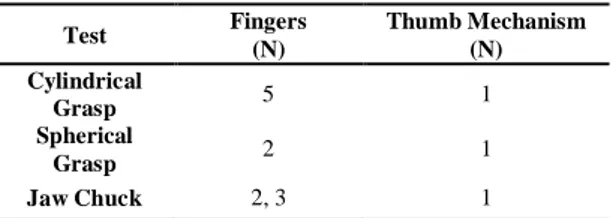
The test results are shown on Table 1, and one can conclude that the maximum load needed to be developed by the linear actuators is 5 N. These values are in line with those obtained by G. Carbone and A.
González in [9].
Table 1 – Actuator Loads
Test Fingers (N) Thumb Mechanism (N) Cylindrical Grasp 5 1 Spherical Grasp 2 1 Jaw Chuck 2, 3 1
4.2FINITE ELEMENT ANALYSIS
The previous mentioned loads are carried through the fingers using the three elements mentioned in Fig.2 as the Connecting Links. These elements will be subject to stresses and deformations that must be supported by their material. As mentioned the prosthetic hand is constructed using the 2024 T3 aluminum alloy, whose main properties are shown on Table 2.
Table 2 – 2024 T3 Mechanical Properties
Property
Density 2780 Kg/m^3
Yield Stress 485 MPa
Ultimate Stress 345 MPa
Young’s Modulus 72,4 GPa
Poisson Coefficient 0,33
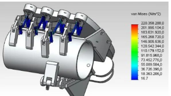
Using the simulations carried above and the Solidworks Finite Element Analysis module, the equivalent Von Mises stress levels were obtained for the connecting links of all fingers (Fig. 10).
Considering the loads applied by the linear actuators and the apprehended objects masses, Table 3, shows the maximum Von Mises stresses for the three prehensions tests carried out.
Fig. 10 Finite Element Analysis carried out on the load carrying finger elements
Table 3 – Maximum Von Mises Stresses
Test Von Mises Stress (MPa) Safety Factor Cylindrical Grasp 220 1.57 Spherical Grasp 168 2.05 Jaw Chuck 19 18.2
As one can see the worst case is the cylindrical grasp. The higher mass for the aluminum cylinder, and the use of all the five fingers, leads to a maximum value of 220 MPa on the connecting elements. The lower loads on the spherical grasp and the jaw chuck prehension simulations lead to lower levels of von Mises stresses on the material.
Considering 345 MPa Yield Stress for the 2024 T3 aluminum alloy used, the results allowed to assess a minimum safety factor of 1.57.
4.3 COST OF PRODUCTION
In Table 4 all the components required to produce a single working prototype are represented, their costs and an estimate of the price of CAD / CAM / CNC labor. The component and material costs were based on market prices and the price of actuators were consulted in the catalog company Firgelli. The cost CAD / CAM / CNC / Beding labors, was based on actual quote cost from faculty to industry.
Table 4 – Components and estimate cost of modelling and manufacturing
5
C
ONCLUSIONS ANDF
UTUREW
ORK The present works allowed the authors to develop a fully functional hand prototype with 6 degrees of freedom, where each finger has one DOF for extension and flexion and the thumb has an extra degree of movement, for thumb opposition (abduction / adduction). Therefore all the fingers simulate the correct anatomical structures.Modeling and Manufacturing
Priceof 42 parts [€] Total price CAD labor Total price of the material Total price CAM/CNC/ bending 311,33 96,38 552,94 Total 960,65 Components Pins Designation Measures Unit Total cost [€]
Grooved (ISO 8744) M3 x 12 16 5,60 M3 x 14 8 2,80 M3 x 8 4 1,40 M3 x 22 1 0,35 M3 x 16 1 0,35 With round head (ISO 8746) M3 x 4 10 3,50 Total 40 14,00
Screws with nut Designation Measures Unit Total cost [€]
Pan head cross recess (ISO 7045) M3 x 16 6 1,20 M3 x 30 1 0,20 M3 x 20 1 0,20 M4 x 35 1 0,20 M5 x 35 1 0,20 Countersunk raised head cross recess (ISO 7047) M3 x 4 4 0,80 Countersunk flat head cross recess (ISO 7046) M4 x 25 4 0,80 M4 x 40 1 0,25 Total 18 3,85 Linear Actuators Unit Price [€] 6 6 x 57,67 Total 6 346,07
Total price of the prosthetic hand [€] 1324,57
The hand prototype is actually slightly bigger and heavier than a normal hand from a male subject.
Three different types of hand prehensions were simulated, using three different objects and several directions for the acceleration of gravity. The prototype hand was successfully capable of apprehending all the objects, using a maximum load of 5 N for all the used linear actuators. The corresponding maximum Von Mises Stress on the connecting links, responsible for the
hand and fingers movement, was
determined to be 220 MPa, and therefore a global 1.57 safety factor is used considering the chosen aluminum alloy.
Finally, an estimate cost of production was made for a single working prototype prosthetic hand, and the result was 1325 €. As for the main future work, the authors are considering a change on the finger design, in order to allow for higher actuator loads, and therefore the prehension for heavier objects. Changing the type of actuator used, in order to reduce the hand cost, and enhance the hand performance [10]. And finally, including a rotating wrist on the project.
REFERENCES
[1] A. C. I. A. Sousa, “A Experiência Vivida da Pessoa com Amputação através do Corpo – Influência Prática de Actividade Física”, Dissertação apresentada com vista à obtenção do 2º ciclo em Actividade Física Adaptada, Faculdade de Desporto da Universidade do Porto, Porto, 2009;
[2] H. Huang, L. Jiang, Y. Liu, L. Hou, H. Cai, H. Liu,” The Mechanical Design and Experiments of HIT/DLR Prosthetic Hand”, IEEE Internacional Conference on Robotics and Biomimetics, Kunming, China, 2006;
[3] R. L. Drake, A. W. Vogl, A. W. M. Mitchell, “Gray´s Anatomy for Students”, Churchill Livingstone, Elsevier, Second Edition, pp. 751-774, 2005;
[4] I. A. Kapandji., “Fisiologia articular – membro superior ”, Editorial Médica Panamerica, Volume I, 5ªedição, pp. 174-283, São Paulo, Brasil, 2000;
[5] J.Yang, E. P. Pittarch, K. A. Malek, A. Patrick, L. Lindkvist; “A multi-fingered hand prosthesis”, Mechanism and Machine Theory 39, pp. 555–581, 2004;
[6] National Aeronautics and Space Administration; “Man-Systems Integration Standards”, Volume I, Section 3, pp. 32-79;
[7] N. Dechev, W. L. Cleghorn, S. Naumann, “Multiple finger, passive adaptive grasp prosthetic hand”, Mechanism and Machine Theory, 36, Pergamon, Elsevier Science Ltd, pp, 1157-1173, 2001;
[8] H. Risley, H. Al-Enazi, N. Noorudeen, H. Al- Qahtani, “Robotic Hand – Phase I”, Department of Electrical & Computer Engineering, Texas A&M, University at Qatar, April, 2010;
[9] G. Carbone and A. González, “A numerical simulation of the grasp operation by LARM Hand IV: A three finger robotic hand,” Robotics and Computer-Integrated Manufacturing, vol. 27, no. 2, pp. 450–459, Apr. 2011; [10] R. G. E. Clement, K. E. Bugler, and C. W. Oliver, “Bionic prosthetic hands: A review of present technology and future aspirations.,” The surgeon : journal of the Royal Colleges of Surgeons of Edinburgh and Ireland, vol. 9, no. 6, pp. 336–40, Dec. 2011;
![Fig. 1 Anatomy of the Human Hand [5].](https://thumb-eu.123doks.com/thumbv2/123dok_br/15762074.1074930/2.892.143.412.199.429/fig-anatomy-human-hand.webp)