CFD Codes Efficiency Case Study: Ability to Perform Numerical
Simulations in the Refrigerated Compartment of a Foodstuff
Transportation Vehicle
Pedro Dinis Gaspar
1, R.A. Pitarma
21Beira Interior University, Rua Fonte do Lameiro – Edifício 1 das Engenharias, 6201-001 Covilhã
email: [email protected]
2Polytechnic Institute of Guarda, Avenida Dr. Francisco Sá Carneiro, n.º 50, 6300-559 Guarda
Summary: The purpose of the present work is to describe the ability of the advanced computer packages
(CFD codes) to perform numerical simulations of general refrigeration engineering problems. The case study concerns the modelling of three-dimensional turbulent airflow with thermal buoyant effects and air temperature distribution in the refrigerated compartment of a perishable foodstuff transportation vehicle. The numerical predictions obtained with three commercial codes (PHOENICS, FLUENT and CFX) and an academic one are evaluated and compared with experimental data. The validation of the numerical results is analysed and the modelling capabilities, usage simplicity and user interface of each code are discussed.
Keywords: Computational Fluid Dynamics, PHOENICS, FLUENT, CFX, refrigeration Category: Modelling techniques
1 Introduction
In a gradual manner the most varied studies in the field of Engineering have been coming to support projects, in the numerical predictions obtained with Computational Fluid Dynamics (CFD) codes. However, these numerical predictions have associated some degree of uncertainty result of the definition of the physical models, and/or by the specifications and simplifications of the mathematical and numerical models used to simulate the physical phenomena.
Although the development of a complex simulation model can be labour intensive and slow requiring huge computational effort, and being unsuitable trust in computational results until reliability and accuracy are established, the significant progress that has been made in CFD commercial codes concerning geometry creation, data transfer between CAD/CAE packages and CFD codes, improvement of the meshing tools, as well as, increasing the numeric robustness and well validated physical models for specific kind of physical phenomena, made them desirable in the design phase. The spread of general-purpose codes allowed the application of CFD in many practical engineering situations. These codes are much more user-friendly in terms of mathematical modelling, numerical techniques and presentation of results, being necessary to compare and assess its potential. Therefore, the scope of the present work is to evaluate the efficiency of three of the most widely used CFD commercial codes (PHOENICS, FLUENT and CFX). The results of the numerical predictions are compared with the obtained through an academic one and validation of the different
numerical results is done comparing them with the experimental results obtained with a reduced physical model developed by dimensional analysis and similarity.
The case study concerns an analysis of the non-isothermal turbulent flow within the refrigerated compartment of a foodstuff transportation vehicle.
1.1 Application of CFD in the refrigeration field
Several numerical studies have been developed in the field of refrigeration to evaluate the airflow and heat transfer, which are references to the present study. In [1] is presented a review of the application of CFD in food processing industries including drying, sterilisation, refrigeration and mixing. Also is presented a summary and a description of some of the common commercial codes that can be used in the food processing industry. In [2] are presented the models developed through numerical methods such as finite difference, finite element and finite volume (this last one is the base formulation of CFD) analysis to describe the heating/cooling processes in the food industry. Concerning the process of refrigeration, [3 – 4] made use of the code PHOENICS to develop respectively computational models of a closed refrigerated display case and of a refrigerated room occupied with products boxes. The aim of these numerical studies was to allow the performance improvement. Likewise, in [5 – 7] is presented the use of code FLUENT to simulate refrigeration appliances. Specifically, the objectives of the studies concerned the improvement of the energy performance through the reduction of the ambient air entrainment. In addition, a novel no-frost range of
refrigerators and freezers was optimised by the evaluation of the circulation of air inside the freezer and refrigerator compartments maintaining the required temperature distribution and preventing the ice formation in the evaporator area. Also the code CFX has been used to predict phenomena in the refrigeration field as presented by [8 – 9]. These computational models help designing refrigerated display cabinets and the simulation of impingement cooling with a slot air jet in a semi confinement area, respectively. There are more applications of CFD in the field of refrigeration making use of others commercial CFD codes (e.g. [10 – 11]) and where the authors developed themselves the codes (e.g. [12 – 13]). This paper is supported by the studies developed by [13] to evaluate the cold air circulation within refrigerated carry chambers. Two methods were developed in that study, one experimental and another computational (CLIMA 3D code), for modelling of non-isothermal turbulent flows in refrigerated chambers including both natural and forced convection. This paper is an extension of the work presented in [14 – 15], since on these studies only was done the comparison of the numerical predictions and the evaluation of the CFD codes efficiency for the case of forced convection. The objectives of this study are the same the above mentioned ones, but the numerical predictions are obtained for the case when the foodstuff compartment is refrigerated by natural convection using eutectic plates.
2. Experimental modelling
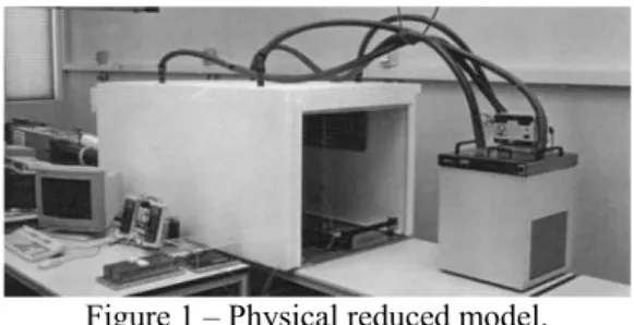
Experiments were conducted to validate the initial computational model developed with CLIMA 3D code. Supporting on these experimental and numerical studies developed by [13], the case study developed to evaluate the commercial codes characteristics and numerical results consists in a foodstuff truck chamber refrigerated by natural convection making use of eutectic plates. The reduced physical laboratory model was developed by dimensional analysis and similarity (Figure 1).
Figure 1 – Physical reduced model.
The similarity between reduced physical model and prototype was obtained by dimensional analysis applying the Buckingham’s π method. The scaling factors obtained for the most relevant variables: Length; Time and Temperature are 2,5; 2,5 and 1,0, respectively. This experimental (reduced) model
consists in a 1,52 × 0,66 × 0,76 m3 box with 6 mm
thick Perspex glass walls. The entire model was insulated with 100 mm thick expanded polystyrene. The temperature and velocity measurements were done in several spatial locations using a probe positioning system. The air temperature measurements were accomplished by a data acquisition system making use of thermocouples (type T, 200 µm wire diameter). The air velocity magnitude measurements were done with a hot-wire anemometer A complete description of the experiment installation can be found in [13].
3. Mathematical modelling
The equations that describe mathematically the airflow and the heat transfer distribution in a refrigerated foodstuff chamber are all based on the three-dimensional (xj) equations for the
conservation of mass, momentum and thermal energy (e.g. [13]). These governing equations for the averaged flow of an incompressible fluid can be written in the general form presented in Equation 1 for a dependent variable φ (=1 for the continuity equation, = u, v, w and T, for momentum and energy equations respectively).
( )
φ φ φ φ S x x x u j j j j = ∂ ∂ Γ ∂ ∂ − ∂ ∂ (1) In this equation, uj represents the mean velocity oneach cartesian direction, Γφ represents the diffusion coefficient and Sφ is the general source term. The Buossinesq approximation is employed to consider buoyancy driven flow in the domain. This force is treated as a source term in the momentum equations. The air is considered as an ideal gas, where the equation of state relates the properties of the substance at equilibrium gas phase state. Although the flow is dominated by natural convection, the standard two-equation k-ε turbulence model was used to closure the set of equations. This turbulence model is based on eddy-viscosity/eddy-diffusivity concepts and involves the solution of two additional partial differential equations for the turbulent kinetic energy (k) and its dissipation rate (ε). This model is analysed in detail by [16]. Because of the damping effect of the wall, the transport equation for the turbulence quantities does not apply close to the wall. Thus, one alternative is to bridge the viscous effects and the steep dependent variables gradients close to solid surfaces through algebraic relations, the so-called logarithmic laws or wall functions for momentum and heat fluxes for the calculation of the velocity parallel to the boundary components and the heat flux through the boundary. The description and implementation details both for the wall functions and turbulence model can be found in [17].
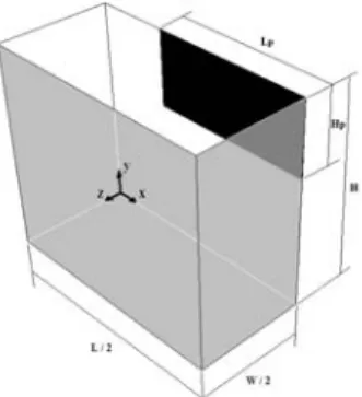
All the evaluated codes rely on the finite volume method to discretised the set of general partial differential equations (Eq. 1). The application of this method converted the equations into a finite set of numerically solvable algebraic equations, as described by [18]. The integration of the equations over a control volume (V.C.) on a mesh yields the finite difference equations. Due to the symmetry of the physical domain, the computational models had a simplified geometry as shown in Figure 2. One quarter of the physical domain was discretise into 13 × 11 × 9 V.C.’s which forms an orthogonal uniform staggered grid with velocity nodes offset from scalars nodes. Grid dependence tests were carried out indicating that the differences between the results in this grid and a double refined grid are not significant.
Figure 2 – Computational models geometry. The boundary conditions imposed in the computational models are present in Table 1.
Table 1 – Boundary conditions (b.c.’s).
Area b.c.’s Prescribed properties
Eutectic plate Fixed temp. Tp= - 20 ºC
Enclosure surfaces Fixed heat fluxes q’’WEST = 7,4 W/m2
q’’EAST (symmetry plane)
q’’BOTTOM = 10,0 W/m2
q’’TOP = 7,4 W/m2
q’’NORTH = 7,2 W/m2
q’’SOUTH (symmetry plane)
The computational models developed with the commercial codes made use of a default type boundary condition for the energy at the walls of mean heat flux value prescription obtained by experimental measurements. One of the main differences of the computational models relies on this boundary condition. In the academic code (CLIMA 3D) the heat transfer modelling was based in the Fourier law to calculate the heat flux across the walls and on the Newton law to calculate the convective heat flux to the ambient air. Firstly, the outer convection heat transfer coefficient is calculated based on experimental results. Then, the heat transfer, supposed as one-dimensional, is calculated by the overall heat transfer coefficient and on the difference between the values of the temperature near the wall and the ambient air
temperature value fixed at 25 ºC. The overall heat transfer coefficient is comprised of the conductive and convective resistances. The first one is based on the knowledge of the thermal conductivity and thickness of the several materials that compose the walls. The other is based on the fixed external convective heat transfer coefficient and on the internal convective heat transfer coefficient calculated through the wall functions. Thus, the heat flux through the wall will vary from this code to the commercial ones, because on these last ones was fixed the mean heat flux value through the walls. This mathematical heat transfer modelling method was not implemented on commercial codes computational models because it would be very time consuming as it was proved through the development of the academic code. In addition, this method was not applied to the computational models developed with the commercial codes because one of objectives of the work is to evaluate their easiness and fastness obtaining numerical previsions if the model is based on the default modelling tools. Besides, this method for the heat transfer modelling could not be applied with code
PHOENICS because it was used a non-recompilable
version.
Afterwards defining the boundary conditions, the scheme used to discretise the convective terms in the general transport equations for all the dependent variables was established. The scheme applied varies from each computational model as exposed in Table 3 depending on availability and uniformity through the computational models created. Details about the discretisation schemes by control volume method can be found in [19].
Table 3 – Discretisation scheme.
MODEL SCHEME NOTES
CLIMA 3D Hybrid (HDS) Programmed
PHOENICS Hybrid (HDS) Default
FLUENT 1st order upwind (UDS) –
CFX 1st order upwind (UDS) –
The method for pressure-velocity coupling, by a global procedure of numerical integration of the flow domain equations, as presented by [18] also differs from each computational model as presented in Table 4.
Table 4 – Pressure-velocity coupling method.
MODEL METHOD NOTES
CLIMA 3D SIMPLE Programmed
PHOENICS SIMPLEST Method available
FLUENT SIMPLE Also: SIMPLEC; PISO
CFX Rhie-Chow Method available
The iterative procedure for solving the algebraic equations varies from each code as can be seen in Table 5.
Table 5 – Solution method.
MODEL METHOD NOTES
CLIMA 3D line-by-line Programmed
PHOENICS TDMA (with SARAH) Default
FLUENT Gauss-Seidel (with AGM) Default
CFX ILU (with MG) Default
The linear relaxation method is used to reduce the high variation of the dependent variables during the iterative procedure of calculation. In Table 6 are exposed the values of the linear relaxation factors for the several scalars and vector variables used for all computational models.
Table 6 – Linear relaxation factors.
φ p uj k ε ρ H T mv
αφ 0,9 0,4 0,4 0,4 0,3 0,9 0,9 0,9
The convergence monitoring was done by the analysis of the sums of the absolute residuals of mean field variables. The iterative procedure run until a prescribed convergence criterion for the normalized residuals (λ ≤ 5.10-3) was met.
4. CFD codes characteristics
The computational models were developed with the intention of predicting the velocity and temperature fields in the reduced-scale model above described. All CFD codes tested stands on the statement that all thermo-fluid problems are governed by the aforementioned principles of conservation. For the self-programmed code (CLIMA 3D), all the numerical techniques described for the solution of the exposed mathematical models were programmed in FORTRAN. In the following lines it will be presented and compared the generic characteristics of each code. It is important to expose (Table 7) that the versions and acquisition date of the codes tested were quite different. Thus, the confidence of the user increases with the practice in each code. This experience is dependent of the acquisition date. So, the code CFX will present higher uncertainty in the numerical predictions, although its friendliness allows the quick development of computational simulations. Due to the deepest knowledge of the other codes, both PHOENICS and FLUENT secure some certainty on the numerical results.
Table 7 – Version and acquisition date of the codes.
MODEL Version Date Notes
CLIMA 3D – – Programmed
PHOENICS 3.1 1997 Non-recompilable FLUENT 6.0 2001 Recompilable
CFX 5.6 2003 Recompilable
Each code was licensed to a hardware and software platform: PC type with Windows NT operative
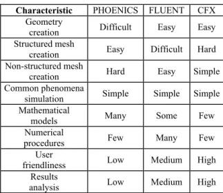
system. At first sight, the difference most significant between the codes consists of its structure. The codes are structured by distinct interlink modules (geometry and mesh builder, pre-processor, solver and post-processor). In Table 8 are summarized the authors personal opinions considering the comparison of the potentialities of the commercial codes.
Table 8 – Comparison of codes characteristics.
Characteristic PHOENICS FLUENT CFX
Geometry
creation Difficult Easy Easy
Structured mesh
creation Easy Difficult Hard
Non-structured mesh
creation Hard Easy Simple
Common phenomena
simulation Simple Simple Simple
Mathematical
models Many Some Few
Numerical
procedures Few Many Few
User
friendliness Low Medium High
Results
analysis Low Medium High
Each code contains several particularities exposed in detail in [14] for codes PHOENICS and FLUENT and in [15] for codes FLUENT and CFX. Furthermore, in these references is exposed the comparison of the characteristics of the aforementioned modules included in each code. Also, for each code can be found in respective user manual details of all the specification issues.
5. Results and discussion
To evaluate the simulation capabilities of codes and to establish the validation of the numerical results, below is presented the comparison of experimental and numerical results of air velocity magnitude and non-dimensional temperature. In Figure 3 is presented one example of the magnitude velocity profile for two planes intersections.
0,0 0,2 0,4 0,6 0,8 1,0 -0,08 -0,04 0,00 0,04 0,08 0,12 0,16 0,20 0,24 0,28 0,32 U x/ (0 ,5 L ) PHOENICS FLUENT CFX EXP CLIMA 3D y/H = 0,95 , z/(0,5W) = 0,96 Figure 3 – Velocity magnitude profile.
The comparison between the experimental data and the different velocities numerical profiles shows a similar trend. The numerical results closer to the experimental data are those that had been obtained with the academic code CLIMA 3D. The numerical velocities predictions obtained with the commercial codes sub– or over–predict the phenomenon. In Figure 4 is presented a temperature profile for two planes intersections.
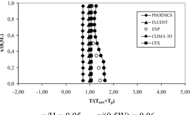
0,0 0,2 0,4 0,6 0,8 1,0 -2,00 -1,00 0,00 1,00 2,00 3,00 4,00 5,00 T/(Tout+Tp) x/ (0 ,5L ) PHOENICS FLUENT EXP CLIMA 3D CFX y/H = 0,95 , z/(0,5W) = 0,06
Figure 4 – Non-dimensional temperature profile. Analyzing the comparison between the experimental data and temperature predictions, the code CLIMA 3D is that which predicts more accurately the temperature profiles within the domain. The numerical results obtained with the commercial codes are very similar, but all sub-predict the temperature. The numerical sub-predictions deviation for temperature obtained with the codes
CFX, FLUENT and PHOENICS increase
respectively. This difference surely is attributed to the b.c.’s imposed at the walls. In Table 9 are presented the mean absolute error of the velocity magnitude ( E(U) = | Uexp – Unum | ) and of
non-dimensional temperature ( E(T*) = |Texp* – Tnum*| ). Table 9 – Mean error of predictions.
CLIMA 3D PHOENICS FLUENT CFX
E(U) 0,017 0,048 0,051 0,036
E(T*) 0,208 0,494 0,226 0,157
Generally, the evaluation of the numerical profiles obtained through the different codes shows a common qualitative agreement with the experimental data. The quantitative deviation of the numerical predictions achieved with the different codes, at some points shows a considerable value from each other and from experimental results. These divergences results from the type and refinement of the mesh created and from the mathematical and numerical models used by the codes. In this specific case, the major source of deviation is due to the boundary conditions imposed at the walls. Summarizing, the comparison between the experimental data and the numerical results obtained with the different codes, shows that
the most realistic numerical predictions were obtained with the code CLIMA 3D. The comparison between the commercial codes shows that the codes CFX, PHOENICS and FLUENT predicts respectively with increasing precision the magnitude velocity. In other hand, the codes CFX, FLUENT and PHOENICS predicted the temperature field with increasing precision respectively. Thus, the code CFX predicts with superior precision the physical phenomenon. In general and independently of the CFD code, the numerical predictions show more agreement for the velocities than for the temperatures. Some effectiveness for the velocity predictions could be attributed to the computational models developed despite the code that is used. Due to the different method of modelling the heat transfer the deviations between the numerical and experimental values of the temperature are important reducing the conviction on the results. Nevertheless, the mean error presented shows the importance of the mathematical model. In Figures 5 - 6 are presented the predictions of the velocity magnitude and temperature fields obtained with code CFX.
(x/0,5L) = 0,96 , z/(0,5W) = 0,06 Figure 5 – Velocity magnitude fields. [m/s]
(y/H) = 0,95 , z/(0,5W) = 0,06 Figure 6 – Temperature fields. [K]
Being one of the objectives of the paper compare the ability of the commercial codes in generating predictions for a simple and common physical phenomenon, these errors were meaningless because if all the potentialities were used, certainly the predictions would be much more precise, but the development of the computational models would be much more time consuming. Generally, the commercial CFD codes make use of the same requisites to the mathematical and numerical
models. Still, each code has different mathematical models that depend on the type of physical phenomenon, and contain different numerical techniques. The errors obtained with all the models should be attributed to the mesh type (quality and refinement), to the mathematical models (simplifications considered), and to the numerical models. In this specific physical phenomenon simulation, the errors should be essentially attributed to the type of boundary conditions considered at the walls.
6. Conclusions
The main purpose of this work was to investigate the difference in modelling physical phenomena of refrigerated rooms with academic self-programmed and commercial codes. The CLIMA 3D was especially developed for this purpose, incorporating a mathematical model more complete. Since the numerical simulations intended to predict the airflow and the heat transfer into the foodstuff chamber of transportation vehicles, an experimental modelling was developed by dimensional analysis to validate the predictions and to give a deeper insight of the physical phenomena. In parallel were developed numerical models with the commercial codes PHOENICS, FLUENT and CFX. The aim was to compare these numerical predictions among them and also with the experimental results. In addition, the codes were compared and evaluated. The elaboration of an isolated code like CLIMA 3D for the prediction of a physical phenomenon is complex and time consuming which could justifies the preferential use of commercial codes. However, the numerical results obtained with this academic code are much closer to the experimental data. Comparing the commercial codes, all of them present differences in the structure, methodology of calculation and easiness of use. The code PHOENICS has the greater amount of mathematical models and validation cases. Also, presents greater easiness on the construction of structured computational meshes. The code CFX presents greater post-processing capabilities since it has higher versatility and simplicity of the user-program interface. Also, has a higher speed convergence of the solution as the complexity of the phenomena increases. But, considering all the features, the code FLUENT seems to be the most equilibrated one. However, all the numerical predictions obtained by these codes can be distrusted. This will come into sight if the definitions of the problem, the specifications and possible simplifications of the mathematical and numerical models considered for the description of the phenomenon aren’t precise. So, the CFD experience of the user is still fundamental and determinative to guarantee the realism of the numerical predictions.
References
[1] Bin Xia and Da-Wen Sun. Applications of computational fluid dynamics (CFD) in the food industry: a review.
Computers and Electronics in Agriculture, 34 (2002).
[2] Lijun Wang and Da-Wen Sun. Recent developments in numerical modelling of heating and cooling processes in the food industry - a review. Trends in Food Science &
Technology, 14 (2003).
[3] S.C. Hu, N.W. Fan and Y-Z R. Hu. Optimization of the display design using numerical models. PHOENICS Journal
of CFD & its applications, 7 (1994).
[4] H.W. Wang and A.H. Visser. 3D flow patterns in refrigerated stores. PHOENICS Journal of CFD & its
applications, 4 (1991).
[5] Graham Sands and Weizhong Xiang. Frost-free chilling.
Fluent News, 11 (2002).
[6] FLUENT Newsletters. CFD helps decrease ambient air entrainment in ice cream freezer by 30%. Journal Articles by
Fluent Software Users, (2001).
[7] FLUENT Newsletters. Advanced design of domestic refrigerators using FLUENT. Fluent News, 8 (1999). [8] A.M. Foster. Using CFD to Model Air Flow and Heat Transfer in and Around Refrigerated Display Cabinets. CFX
Todays Research for Tomorrows Applications, Reading,
United Kingdom, March 2000.
[9] E.E.M. Olsson, L.M. Ahrné and C. Trägårdh. Impingement cooling of solid cylindrical foods using CFD.
FOODSIM’2002, Blarney, Ireland, June 2002.
[10] P. Bhattacharjee and E. Loth. Simulations of laminar and transitional cold wall jets. International Journal of Heat
and Fluid Flow, 22 (2004).
[11] Garry Palmer. Benefits of new refrigerated cabinet design by measurement of air temperatures and velocities on-site. Oscar Faber Applied Research, (2000).
[12] J.J. Costa and L.A. Oliveira. Vedação aerodinâmica por cortina de ar – Estudo numérico. I Jornadas Técnicas de
Primavera da EFRIARC, Porto, Portugal, March 2001.
[13] R.A. Pitarma. Modelação matemática e experimental de câmaras frigoríficas de veículos. PhD Thesis, Instituto Superior Técnico, Universidade Técnica de Lisboa, Lisboa, April (1998).
[14] P.D. Gaspar, R.F. Barroca and R.A. Pitarma. Performance Evaluation of CFD Codes in Building Energy and Environmental Analysis. Building Simulation 2003, Eindhoven, Holand, August 2003.
[15] P.D. Gaspar and R.A. Pitarma. Evaluation of CFD codes by comparison of numerical predictions of an air-conditioned room case study. 8th Int. Conference on
Advanced Computational Methods in Heat Transfer, Lisbon,
Portugal, March 2004.
[16] B.E. Launder and D.B. Spalding. The numerical computation of turbulent flows. Computer Methods in
Applied Mechanics and Engineering, 3 (1974).
[17] W. Rodi. Turbulence models and their application in
hydraulics – A state of the art review, IAHR, (1980).
[18] S.V. Patankar. Numerical heat transfer and fluid flow. Hemisphere Publishing Corporation, McGraw-Hill, (1980). [19] D.B. Spalding. A novel difference formulation for differential expressions involving both first and second derivatives, International Journal for Numerical Methods in