Jorge Cebola Borbinha
Bachelor of Science
Organ Dose Estimates in Thorax CT:
Voxel Phantom Organ Matching With
Individual Patient Anatomy
Dissertation submitted in partial fulfillment of the requirements for the degree of
Master of Science in Biomedical Engineering
Supervisor: Salvatore Di Maria, PhD, C2TN - IST
Co-supervisors: Pedro Vaz, PhD, C2TN - IST
Ana Paula Madeira, MsC., Radiographer,
Organ Dose Estimates in Thorax CT: Voxel Phantom Organ Matching With Individual Patient Anatomy
Copyright © Jorge Cebola Borbinha, Faculty of Sciences and Technology, NOVA University of Lisbon.
The Faculty of Sciences and Technology and the NOVA University of Lisbon have the right, perpetual and without geographical boundaries, to file and publish this dissertation through printed copies reproduced on paper or on digital form, or by any other means known or that may be invented, and to disseminate through scientific repositories and admit its copying and distribution for non-commercial, educational or research purposes, as long as credit is given to the author and editor.
This document was created using the (pdf)LATEX processor, based in the “novathesis” template[1], developed at the Dep. Informática of FCT-NOVA [2].
A c k n o w l e d g e m e n t s
First of all, a great vote of appreciation goes to my thesis supervisor, Salvatore di Maria. I thank him for the patience, support and thoughtfulness he provided both on a professional and personal level, making the adventure shown in this document possible and worthwhile.
My sincere thankfulness goes to my co-supervisors, Paula Madeira and Pedro Vaz, for their dedication and availability, which made this project possible.
I would like to express my gratitude to FCT-UNL for all the knowledge and experience given, which allowed me to grow both on a professional and personal level, and for the beautiful campus, to which I fell in love at first sight. I would also like to thank C2TN
and HSJ, whose collaboration allowed me to undertake my master’s thesis on a subject I love.
To all people whom I shared my workspace with, I am thankful for all the assistance and companionship provided. I thank Rita Monteiro for providing me with company and good advice during the better part of my thesis. A special mention goes to my sincere friend, Débora António, who accompanied me from the very beginning of our course of Biomedical Engineering until now, the very end.
To my father, Manuel, and my mother, Clementina, I would like to say that, if I was able to climb up the ladder, it is because I stood on your shoulders. I express my deepest gratitude to you for providing me every tool I need to have a great future. My heartfelt thankfulness goes to my grandfather, Crispim Cebola, for being the amazing person he is and for his farm’s vegetables that gave me the strength needed to finish this thesis.
A great vote of appreciation goes to my dear friend, Bruno Catita, for the strength and motivation he inspires in me. My gratitude to my friend João Calisto, for all the moments, adventures and laughs we shared. I also thank my friend, Filipe Lacerda, who I have known for more time than I can remember. Thank you for the journey of a lifetime, may it go on for many years.
A b s t r a c t
Given the continuous usage and spread of computed tomography (CT), the potential harmful effects and the radiation dose to the patient have become high interest topics
among the scientific community.
The main objective of this investigation was to modify existing three-dimensional (3D) voxel phantom models to resemble real patients as much as possible, trying to progress the concept of a more personalized patient dosimetry. This work focused essentially in one of the biggest and most radiosensitive organs in the thorax, the lungs. Additionally, the variations of organ doses when a standard phantom is used instead were studied.
During the course of this work a FORTRAN-based program was developed, which is able to semi-automatically modify the volumetric information of organs of interest in a standard voxel phantom (Female ICRP Adult Reference). The voxel resolution was also altered so the phantom’s diameters match the patient’s ones. Monte Carlo (MC) PENE-LOPE simulation code was used to mimic CT scan conditions and, therefore, generate 2D projections, used for visual organ matching with clinical patient CT images, and access organ dose in both phantoms (ICRP standard and ICRP modified).
The main results reported that matching the voxel phantom’s size and lungs provides organ dose values significantly different from the ones measured in the ICRP reference
phantom. Voxel models matched to patients’ size and overall anatomy allow increased accuracy in organ dose estimation, which, as reported by this study, can suffer from up
to 20% underestimation and 40% overestimation.
This study demonstrates that voxel phantoms developed using single patient data provide a better and more precise organ dose assessment by MC methods than a standard phantom. The presented methodology should be of interest for dose optimization studies and quick enough for routine clinical use.
Keywords: Computed Tomography, Voxel Phantom, Monte Carlo Methods, Organ Dose,
R e s u m o
Dado o contínuo uso e expansão da tomografia computorizada (TC), os potenciais efeitos nocivos para a saúde e a dose radiativa para o paciente tornaram-se tópicos de elevado interesse para a comunidade científica. O principal objectivo desta investigação foi modificar fantomas devoxelpara que se assemelhem a pacientes reais o mais possível, tentando assim desenvolver o conceito de dosimetria específica ao paciente. Este traba-lho focou-se essencialmente num dos maiores e mais radiosensíveis órgãos do tórax, os pulmões. Adicionalmente, foram estudadas as variações de dose nos órgãos quando o fantoma de referência e o fantoma adaptado são utilizados.
Ao longo deste trabalho um programa foi desenvolvido em FORTRAN, capaz de modificar semi-automaticamente a informação volumétrica de órgãos de interesse num fantoma de voxel(Adulto Feminino de Referência do ICRP). A resolução dosvoxels foi modificada para que os diâmetros dos fantomas correspondam aos do paciente. O código Monte Carlo (MC) PENELOPE foi utilizado para replicar as condições de um equipamento de TC, de forma a obter projeções em 2D e valores de dose em ambos os fantomas (ICRP referência e ICRP modificado).
Os resultados mostraram que a adaptação do tamanho e dos pulmões de fantomas de voxel providencia valores de dose nos órgãos bastante diferentes dos medidos no fantoma de referência. Fantomas devoxelcom tamanho e pulmões adaptados permitem maior precisão na obtenção de valores de dose nos órgãos, que podem ser subestimados e sobrestimados até 20% e 40%, respetivamente.
A presente dissertação demonstra que a utilização de fantomas devoxeladaptados aos dados de pacientes individuais providencia, através de métodos MC, valores de dose nos órgãos mais precisos do que um fantoma de referência. A metodologia apresentada deve ser útil para estudos de otimização de dose, assim como rápida o suficiente para aplicações clínicas de rotina.
Palavras-chave: Tomografia Computorizada, Fantoma de Voxel, Métodos Monte Carlo,
C o n t e n t s
List of Figures xix
List of Tables xxi
Acronyms xxiii
1 Introduction 1
1.1 Motivation . . . 1
1.2 Objectives . . . 6
1.3 Thesis Outline . . . 6
2 Theoretical Fundaments 9 2.1 Interaction of Radiation with Matter . . . 9
2.2 Fundaments of Computed Tomography . . . 10
2.3 The Radiation Protection International System . . . 12
2.4 Fundaments of Dosimetry . . . 13
2.4.1 Radiometric Quantities . . . 13
2.4.2 Dosimetric Quantities . . . 14
2.4.3 Dosimetric Quantities in CT . . . 15
3 Dose Estimates in the Patient 19 3.1 Dose Estimates using Physical Phantoms . . . 20
3.2 Dose Estimates using Computational Phantoms . . . 21
3.2.1 Stylized Phantoms . . . 22
3.2.2 Voxel Phantoms . . . 22
3.2.3 BREP Phantoms . . . 24
3.3 Patient and Organ Dose Estimates Using MC Methods and Computational Phantoms . . . 24
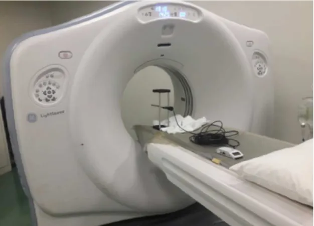
4 Materials and Methods 29 4.1 CTDI Measurements . . . 29
4.1.1 CT Equipment . . . 30
4.1.2 Ionization Chamber . . . 30
C O N T E N T S
4.1.4 Measurement Procedure . . . 30
4.1.5 Results Procedure . . . 32
4.2 The Male and Female ICRP Reference Phantoms . . . 33
4.3 The FORTRAN Programming Language . . . 34
4.4 Visualization and Simulation Files Program . . . 34
4.5 Organ Scaling Program . . . 35
4.6 Patient/Phantom Matching Procedure . . . 39
4.6.1 Description of the Patient CT Images . . . 39
4.6.2 Matching the Phantom Size . . . 40
4.6.3 Matching the Lungs Dimension . . . 40
5 The Monte Carlo Method 43 5.1 MC Fundaments . . . 43
5.2 PENELOPE . . . 44
5.3 PenEasy . . . 45
5.4 Implementation of CTDI Measurements . . . 47
5.4.1 Geometry and Source Definition . . . 47
5.4.2 Materials Definition . . . 48
5.4.3 Spectrum Definition . . . 48
5.5 Implementation of Scaled Phantoms MC Simulations . . . 49
5.5.1 Geometry, Source and Materials Definition . . . 49
5.5.2 Dose vs Voxel Volume Simulations . . . 50
5.5.3 Scaled Lungs Phantom Simulations . . . 51
6 Results and Discussion 53 6.1 MC Model Validation . . . 53
6.2 Dose vs Voxel Volume Results . . . 55
6.3 Results from Patient/Phantom Matching Procedure . . . 58
6.3.1 AF Size Measurement . . . 58
6.3.2 Patient and Phantom Size Measurement . . . 58
6.3.3 Results from Matching the Patient Size . . . 60
6.3.4 Results from Matching the Lungs Size . . . 62
6.3.5 Visual Comparison of Patient and Phantom Images . . . 64
7 Conclusions and Future Work 69
8 References 73
A Lists of Materials and Organs Used in Voxel Phantom Simulations 79
B Tally and 36-Point Interpolation Results from MC Model Validation 81
C Lung Size Values Before and After Patient/Phantom Matching Procedure 85
C O N T E N T S
L i s t o f F i g u r e s
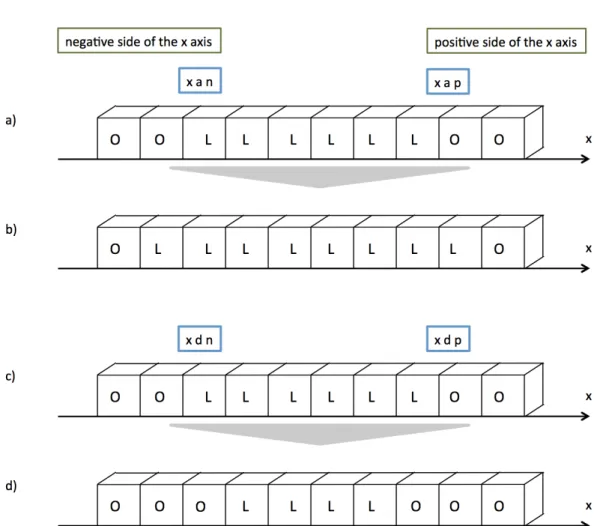
1.1 Trends in the annual frequency of diagnostic x-ray examinations in function
of health care level. . . 2
1.2 Number of CT scans performed per 100 000 inhabitants in several European countries in 2009 and in 2014. . . 3
1.3 There are several proposed models to explain the dose-response curve between radiation exposure and carcinogenic risk. . . 4
2.1 Alan MacLeod Cormack and Godfrey Newbold Hounsfield are the co-creators of Computed Tomography. . . 10
2.2 Set of four figures illustrating the concept of Computed Tomography Dose Index (CTDI). . . 16
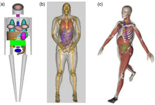
3.1 Depiction of the three computational phantom generations. . . 21
3.2 Comparison of a stylized adult phantom and the VIP-Man phantom. . . 23
3.3 Whole body models with Computed Tomography (CT) data appended at the top and bottom of the scanned volume with data from computational phan-toms used in the study performed by Kalender et al. . . 27
4.1 The polymethylmethacrylate (PMMA) phantom used in this work. . . 31
4.2 The General Electric Company (GE) CT equipment used when performing the measurements. . . 31
4.3 Representation of the action ReDimLungs takes when scaling a x-array. . . . 38
4.4 Workflow diagram of the patient/phantom matching procedure. . . 42
5.1 Representation of a cross section of the phantom passing trough the x=0 plane for the situation of the chamber at the center of the phantom. . . 47
5.2 Graph of the x-ray spectrum used in the MC simulations. . . 49
6.1 Graph for TRENDXY. . . 56
6.2 a)Graph for TRENDX. b)Graph for TRENDY. . . 57
6.3 Visualization, using the Gnuplot tool, of Adult Female (AF)’s slice 238. . . . 58
L i s t o f F i g u r e s
6.5 Variation of organ dose in relation to the AF phantom for all resolution phan-toms. . . 62 6.6 Variation of organ dose in relation to the AF phantom for the patient phantoms. 63 6.7 a)Image of the AF phantom obtained via the tally pixelated imaging detector.
b)CT image topogram for Patient 1. c) Image of AF1 obtained via the tally pixelated imaging detector. . . 65 6.8 a)CT image topogram for Patient 2. b)Image of AF2 obtained via the tally
pixelated imaging detector. . . 66 6.9 a)CT image topogram for Patient 3. b)Image of AF3 obtained via the tally
pixelated imaging detector. . . 66 6.10 a)CT image topogram for Patient 4. b)Image of AF4 obtained via the tally
pixelated imaging detector. . . 66 6.11 a)CT image topogram for Patient 5. b)Image of AF5 obtained via the tally
pixelated imaging detector. . . 67 6.12 a)CT image topogram for Patient 6. b)Image of AF6 obtained via the tally
pixelated imaging detector. . . 67
B.1 Example of graph of 36-interpolation of the tally values, for the Ionization Chamber (IC) at 0º position. . . 83
L i s t o f Ta b l e s
2.1 Recommended tissue weighing factors for various organs and tissues. . . 15
4.1 Main characteristics of the International Commission on Radiation Protection (ICRP) male and female reference phantoms. . . 34
5.1 Material list present at the PENELOPE section of the PenEasy input file. . . . 48
6.1 Dose,CT DI100 andCT DIW values measured for the ionization chamber in-serted in each orifice of the PMMA phantom. . . 54
6.2 Dose, respective uncertainty and CTDI100 and CTDIW simulated values, as well as the relative difference between measured and simulated values, for every ionization chamber location. . . 54
6.3 L and AP diameters measured in the patients’ CT images and in the simulated images of the resolution phantoms and relative difference between them. . . 60
A.1 List of the organs present in the organ list of the AF phantom. . . 79
A.2 List of the materials defined in the PENELOPE section of the PenEasy input file. . . 80
B.1 Tally and interpolation results for the IC in-air position. . . 81
B.2 Tally and interpolation results for the IC at center position. . . 82
B.3 Tally and interpolation results for the IC at 0º position. . . 82
B.4 Tally and interpolation results for the IC at 90º position. . . 82
C.1 Left lung size in x, y and z measured in the patients’ CT images and in the patient phantoms and relative difference between them. . . 86
A c r o n y m s
2D Two-Dimensional. 3D Three-Dimensional.
AAPM American Association of Physicists in Medicine.
AF Adult Female.
ALARA As Low As Reasonably Achievable.
AP Anterior-Posterior Diameter.
ASCII American Standard Code for Information Interchange.
BREP Boundary Representation.
BSS Basic Safety Standards.
CAD Computer Aided Diagnosis.
CF Conversion Factor.
CSG Constructive Solid Geometry.
CT Computed Tomography.
CTDI Computed Tomography Dose Index.
AC R O N Y M S
CTDIW Weighted Computed Tomography Dose Index.
DLP Dose-Length Product.
EMI Electric and Musical Industries.
EURATOM European Atomic Energy Community.
FDA Food and Drug Administration.
FOV Field of View.
GE General Electric Company.
HNBR High Natural Background Radiation.
HSJ-CHLC Hospital São José – Centro Hospitalar Lisboa Central.
IAEA International Atomic Energy Agency.
IC Ionization Chamber.
ICRP International Commission on Radiation Protection.
ICRU International Commission on Radiation Units and Measurements.
ID Identification Number.
IEC International Electrotechnical Commission.
Kerma Kinetic Energy Released to Matter.
L Lateral Diameter.
LDR Low Dose Radiation.
LNT Linear Non-threshold.
AC R O N Y M S
MC Monte Carlo.
MF Magnification Factor.
MRI Magnetic Resonance Imaging.
MSAD Multiple Slice Dose Average.
MSCT Multi-slice Computed Tomography.
ORNL Oak Ridge National Laboratory.
PET Positron-Emission Tomography.
PMMA polymethylmethacrylate.
POSDE Patient and Organ Specific Dose Estimate.
SI International System of Units.
SSDE Size-Specific Dose Estimate.
UF University of Florida.
UNSCEAR United Nations Scientific Committee on the Effects of Ionizing
Radia-tion.
Chapter
1
I n t r o d u c t i o n
1.1 Motivation
The application of engineering techniques to a wide variety of fields in the clinical realm has allowed tremendous scientific and technological advances in diagnosis and treatment of various pathologies. CT is a highly informative medical imaging method that allows for better and more efficient patient diagnosis. This is possible through the use
of ionizing radiation to visualize internal anatomical structures with minimal intrusion [1].
Over the last 20 years, a high level of constant innovation by the CT equipment man-ufacturers allowed faster and easier image acquisition, better diagnostic capabilities and the introduction of new techniques. These factors encouraged high frequency usage of the technique, as well as the consequent increase in population exposure to ionizing radiation [1], [2].
C H A P T E R 1 . I N T R O D U C T I O N
the field of diagnostic radiology, more accurate dose calculation methodologies improve imaging department professionals’ information regarding patient and organ dose. Con-sequently, physicians and radiologists will be able to make more informed decisions on the scan’s performance, imaging protocol and even whether to perform the exam or not. According to United Nations Scientific Committee on the Effects of Ionizing Radiation
(UNSCEAR) data, there are approximately 3.6 billion diagnostic radiology X-ray examina-tions undertaken annually in the world. Additionally, approximately two thirds of these exams are performed on the 24% of the population living in health care level I countries (Figure 1.1). About 11% of CT examinations are performed in a pediatric population [1].
Figure 1.1: Trends in the annual frequency of diagnostic x-ray examinations in function of health care level [1].
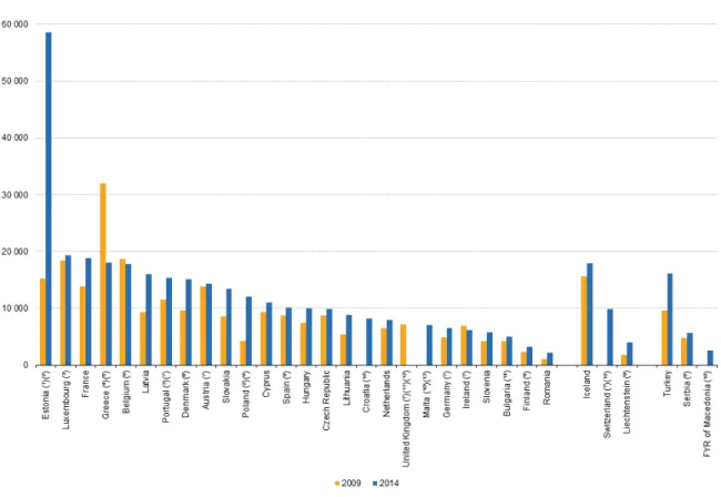
In the United States, the number of CT scans increased from about 3 million in the 1980s to 67 million in 2006 [6], [7]. According to Eurostat, between 2009 and 2014, both the number of CT scanners and exams relative to population size increased in almost all the European countries, as illustrated in Figure 1.2. Portugal is the seventh European country with more CT scans relative to population size, with more than 15 000 CT scans per 100 000 inhabitants performed in 2014 [8]. Only in 2014, over one and a half million CT exams were performed in Portugal, corresponding to more than five times the number of Magnetic Resonance and Positron-Emission Tomography (PET) scans done in the same timeline. In addition, 228 CT scanners were counted in Portugal in 2014 [8].
1 . 1 . M O T I VAT I O N
Figure 1.2: Number of CT scans performed per 100 000 inhabitants in several European countries in 2009 and in 2014. Adapted from [8].
Despite CT’s high quality of disease diagnosis, examinations are generally associated with significantly higher doses of ionizing radiation than conventional radiology. There-fore, CT has become the main source of ionizing radiation used in the medical diagnosis field. Though it only represents 5-10% of imaging procedures, as much as 40-70% of the collective dose associated with medical examinations is attributed to CT [1], [2].
Whether there is a cumulative damaging effect or carcinogenic risk after repeated CT
examinations, as well as its underlying biological basis, have become quite controversial subjects in the scientific community. The Fukushima Nuclear Power Station leak in 2011 raised the question of whether human health might be damaged by environmental high-level radiation. This has caused widespread concern and revitalized the debate of the beneficial and injurious effects of Low Dose Radiation (LDR) [2].
The damaging effects of LDR are mainly supported by the Linear Non-threshold
C H A P T E R 1 . I N T R O D U C T I O N
investigation by Bernier et al. compiled three studies accessing carcinogenic risk related to CT examinations on children and young adults. Two studies performed in Australia and the United Kingdom perceived an excess risk of cancer and leukemia associated with CT exposure in childhood [10], [11], [12]. An increased risk, though non-significant, was also the result of a smaller Taiwanese study performed by Huang et al. [10], [13]. The existence of radiation hypersensitivity, suffered by 5-10% of individuals, also supports
this side of the argument [14].
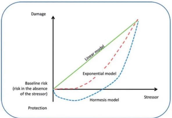
Figure 1.3: There are several proposed models to explain the dose-response curve between radiation exposure and carcinogenic risk. The LNT hypothesis states that the cancer risk is directly proportional to the dose level of ionizing radiation. In the case of the exponential model, the risk of cancer increases exponentially with the dose level of ionizing radiation. The hormesis model defends that LDR actually possesses protective effects, though higher
doses are damaging to human health. Adapted from [2].
On the other side, the observation of hormesis (Figure 1.3) and adaptive response supports the beneficial effects of LDR. The concept of hormesis is based on some positive
effects of LDR, such as enhanced immunity or increased lymphocyte transformation rate.
Adaptive response refers to a protective mechanism, stating that a previous exposure to LDR may attenuate the damage caused by following high dose radiation. An investigation was carried out by Liu et al. among the High Natural Background Radiation (HNBR) population in China. Conclusions stated that lymphocyte percentage and transformation rates were higher in the group exposed to HNBR than in the control group. Additionally, a 36-year follow up study observed a reduction on the frequency of cancer in the exposed group [2]. In another investigation, the interventional cardiologists who were most likely
1 . 1 . M O T I VAT I O N
to come into contact with radiation in hospital were considered (with median exposure of 4mSv/year). The authors found that LDR may enhance the antioxidant defence system and increase apoptosis susceptibility (to remove damaged cells efficiently) after 2Gy of
irradiation [15].
Nowadays Computed Tomography examinations suffer from five main problems,
which are listed as follows.
1. The first issue is the high frequency usage of CT scans. Brenner et al. state more than one third of CT scans are either unnecessary or could easily be replaced by other imaging techniques, such as magnetic resonance imaging [16].
2. The patients’ exposure to ionizing radiation is now higher than ever before. Ra-diation and cumulative doses in the patient have increased greatly, mainly due to the technological advancements of Multi-slice Computed Tomography (MSCT) and helical CT [17].
3. Proper attention to radiation sensitive groups is also very important, since children are about four times more sensitive to radiation than adults [18].
4. Given that different organs in the human body suffer from different
radiosensitiv-ities, CT radiation may vary significantly according to different parameters and
scanning areas. Dose assessment in radiosensitive organs, such as the thyroid, is of uttermost importance [2].
5. The last issue refers to poor understanding of carcinogenic risks by both patients and professionals. A study, performed in the Emergency Department of an Amer-ican academic medical center, revealed that only 7% of patients reported having been informed on benefits and risks before performing a CT scan. Additionally, 47% of radiologists and 9% of imaging department physicians did not believe CT would increase cancer risk [19].
Dose in CT is a subject that has received appropriate attention since CT’s introduc-tion in the diagnostic realm in the 1970s. Efforts addressed both scanner characteristics
and patient dose aspects. As the investigation on dose metrics evolved, the CTDI was defined. This parameter, measured in PMMA cylindrical phantoms, is largely used and acknowledged worldwide [20].
In the 1990s, the growing computational power allowed for the dissemination of Monte Carlo (MC) techniques, computational algorithms that rely on repeated random sampling to obtain results. Several radiation physics MC codes were developed, being able to accurately simulate radiation transport, as well as sources, detectors and other bodies. Some examples of these codes are PENELOPE, GEANT, MCNP/MCNPX, etc. [21]. Given the clear difficulties in measuring absorbed dose in patients, the subject of dose
C H A P T E R 1 . I N T R O D U C T I O N
the Size-Specific Dose Estimate (SSDE), which is still grounded on the use of PMMA phantoms [22]. Nowadays, the use of computational phantoms has greatly evolved. This subject will be further explored and reviewed in Chapter 3.
With all the aforementioned factors in consideration, the reduction of CT radiation exposure to the population is urgent, as well as the improvement of population awareness, in order to avoid high cancer incidence down the line. The development of better and more precise methods for patient and organ dose calculation is essential to provide better quality medical diagnostic with minimal risk to the patient and, consequently, improve public health.
1.2 Objectives
The main aim of this investigation was to modify existing Three-Dimensional (3D) voxel phantom models, so to adapt average models to single patient anatomies, trying to ideally approximate to a more personalized patient dosimetry. To accomplish this, a program needed to be developed. The FORTRAN program here developed is able to create a voxel phantom adjusted to a specific patient, by changing the overall size of the patient, as well as modifying the voxel phantom’s organ dimensions. This work focused essentially in one of the biggest and most radiosensitive organs in the thorax, the lungs. Organ doses in several body organs were also calculated using the PENELOPE software, in order to compare organ doses between the standard voxel phantom and the patient adapted voxel phantom.
1.3 Thesis Outline
The present dissertation is distributed over seven chapters. Chapter 1 presents a broad description of the Computed Tomography’s current status as an area of research, illustrated by some significant statistics. The dissertation’s aims are also described here. This chapter ends with a description of the thesis outline.
InChapter 2 information on the subject of interaction of radiation with matter is
presented, followed by a brief review of the main historical landmarks of CT, as well as its constitution and functioning. In addition, an overview of basic theoretical concepts of dosimetry, as well as of several CT dosimetry parameters, is presented.
Chapter 3 contains the actual state of the art of this dissertation. In this chapter,
several methods to determine patient dose in CT are presented and reviewed. First are presented the dose estimates in CT using physical phantoms, followed by the evolution and characteristics of the usage of computational anthropomorphic phantoms. Finally, some techniques using computational phantoms to provide organ dose estimates are presented.
Chapter 4includes the materials and methods applied in this dissertation. It starts
with a description of the hardware used to perform measurements. The measurement
1 . 3 . T H E S I S O U T L I N E
procedure is also explained. Additionally, thorough description and functioning with the ICRP Reference Phantoms are presented. As to the software developed during the thesis, a detailed overview of its purpose and functioning are depicted. Also, in this chapter, the patient/phantom body and lung matching procedures are presented.
InChapter 5the Monte Carlo methods are briefly described and the PENELOPE and
PenEasy MC codes are succinctly explained, followed by an explanation of the PenEasy input file. Additionally, the MC implementation of CTDI measurements, as well as of the standard ICRP and modified voxel phantoms, is thoroughly described.
Chapter 6 presents the results and discussion. Finally, in Chapter 7 the general
Chapter
2
T h e o r e t i c a l F u n d a m e n t s
This chapter begins with an introduction to the field of interaction of radiation with matter, followed by a brief review of the main historical landmarks of CT, as well as its constitution and functioning. Additionally, an overview of basic theoretical concepts of dosimetry, as well as of several CT dosimetry parameters, is presented.
2.1 Interaction of Radiation with Matter
Radiation can be classified into two main categories: non-ionizing and ionizing, de-pending on its ability to ionize matter. The ionization potential of atoms, i.e., the mini-mum energy required for ionizing an atom, ranges from a few electron volts to 24.6 eV. Ionization potentials of all other atoms are between the two extremes.
Ionizing radiation may be classified in directly ionizing radiation and indirectly ion-izing radiation. Directly ionion-izing radiation corresponds to charged particles, such as protons, electrons, alpha particles and heavy ions. These particles deposit their energy in the absorber through Coulomb interactions with the nucleus and electronic cloud of the absorber’s atoms. Indirectly ionizing radiation relates to particles with neutral charge, such as photons and neutrons. This type of radiation deposits its energy in the absorber material through a two step process. On a first step, the neutral particles interact with the nucleus and/or orbital electrons of the absorber, originating charged particles in the process. In the second step, the charged particles will deposit their energy directly on the absorber’s atoms through the aforementioned process [23].
C H A P T E R 2 . T H E O R E T I CA L F U N DA M E N T S
distance before interacting with a nucleus or electronic cloud of the absorber’s atoms [24]. There are essentially five types of interactions photons may have with matter: pho-toelectric effect, compton (incoherent) effect; rayleigh (coherent) effect, pair production
and photonuclear reaction. Depending on the photon energy and the absorber’s atomic number, some interaction processes may occur with higher probability than others, con-tributing more to the attenuation of the photon beam [23]. Considering that diagnosis radiological imaging usually uses energies between 15 and 150 keV, it is possible to in-fer what are the most relevant processes. The energy range used in diagnostic medical imaging promotes photoelectric effect, Compton effect and Rayleigh Effect [25].
2.2 Fundaments of Computed Tomography
X-ray CT triggered a revolution in the field of medical imaging. The two people generally credited with the invention of Computed Tomography, Allan Cormack and Godfrey Hounsfield (depicted in Figure 2.1), were awarded the Nobel Prize for Physiology or Medicine in 1979. After the publication of Cormack’s theoretical idea, the work of Hounsfield at the Central Research Laboratories of Electric and Musical Industries (EMI) Ltd. allowed the construction of the first CT scanner [26]. At the time, EMI was the record company of the Beatles. It has been claimed that only due to the band’s massive success EMI was able to fund Hounsfield’s research, making development of CT a direct result of the Beatles’ sucess [27].
Figure 2.1: Alan MacLeod Cormack (left) and Godfrey Newbold Hounsfield (right) are the co-creators of Computed Tomography [26].
2 . 2 . F U N DA M E N T S O F C O M P U T E D T O M O G R A P H Y
In late 1973, the first commercial CT scanner, the EMI CT 1000 was on the market. Comparing the first scanners available in the market with today’s successors, it is as-tonishing how much progress has been made in their design and manufacture in only a few decades. The EMI CT 1000’s scan took about 4.5 minutes and presented an 80x80 pixels image matrix, while contemporary CT scanners can scan in few hundred millisec-onds and reconstruct an image of 2048x2048 pixels [26]. Nowadays, CT is a 3D whole body imaging procedure suitable for a broad range of applications, including cardiology, angiography, interventional radiology, oncology and radiotherapy planning [28].
CT is an imaging method that allows the acquisition of Two-Dimensional (2D) images from 3D anatomy using a mathematical technique known as reconstruction. When an x-ray beam travels through a patient, it is attenuated differently by different body structures
(with different densities). Therefore, CT is an exam only sensitive to density differences,
representing images on a gray scale [27]. In one acquisition, the x-ray tube and detector array (which are diametrically opposed) rotate 360º in the slip ring around the patient, acquiring different images (called projections) and measuring the attenuation of x-rays
with constant spacing. When a rotation is completed, the calculated attenuation values are used by a reconstruction algorithm to obtain a 2D image in the axial plane, also known as slice. Several image sets are obtained by ’slicing’ the patient’s body several times at different coordinates along the longitudinal axis of the patient. The resulting
images are reconstructed in the sagittal and coronal planes. CT can then be understood as an extension to conventional planar X-rays [29].
Though there have been differences in design through different generations of
scan-ners, the main components in a CT equipment are:
• Thegantryis a circular support into which the patient is moved during the scan. This component allows the X-ray source and the detector array to rotate diametri-cally opposed and synchronously in the slip ring;
• Theslip ringis a structure located within the gantry that passes electrical power to the rotating components of the CT, such as the x-ray tube and the detector array, allowing them to rotate continuously around the patient;
• TheX-ray tube/sourceis the source of the X-rays that pass through the body within the gantry and transmit the information about the body’s structure to the detectors. This information is in the form of a series of projections;
• Thedetector arrayreceives several radiation intensities from X-ray beams that have passed the examined body and converts them to electrical quantities; which are then used in image reconstruction;
C H A P T E R 2 . T H E O R E T I CA L F U N DA M E N T S
Nowadays, CT scans available on the market are accompanied by software that allows utilization and control of CT equipment. Through these softwares, radiologists can access several dosimetric parameters, many times even before the exam (the parameters pre-sented before the exam are calculated using PMMA phantoms) [20], [22]. The availability and technological advent of CT encourage a high frequency use of the technique and raise the dose to the patient in each exam, respectively. Given the possible harmful effects
of ionizing radiation to public health, the use of ionizing radiation in any field of study should be scrutinized and regulated.
2.3 The Radiation Protection International System
Ionizing radiation has been used in the fields of medicine, industry, power generation, waste management and weapon production. Ionizing radiation has the potential to greatly benefit people’s quality of life, but only if it is used safely. Potential risks must be accessed and controlled [23], [30].
The Radiation Protection International System rests on the protection of individuals and environment from the hazardous effects of ionizing radiation. Specific radiation
protection rules and standards, such as the ones recommended by ICRP and International Commission on Radiation Units and Measurements (ICRU), are traditionally applied to the "peaceful use of atomic energy". Different criteria might be used for applications such
as space exploration or military purposes [24]. Around the world there are other agencies that also contribute to regulate radiation usage and establish several dosimetric quantities and units, which allow easier and more accurate dose assessment. UNSCEAR compiles and examines scientific knowledge published around the world and materializes it in its reports. The International Atomic Energy Agency (IAEA) establishes scientific and technical international cooperation in the nuclear field, as well as Basic Safety Standards (BSS). BSS stipulate security regulations in all ionizing radiation related sectors. In the European Union, the European Atomic Energy Community (EURATOM) works closely with ICRP and IAEA. This agency establishes general principles for radiological security and protection, as well as the correct usage of ionizing radiation [28], [30], [31].
The Radiation Protection International System articulates around three fundamental principles. These principles, established by the ICRP and published in the ICRP-60 publication in 1990, are defined as follows:
• The principle ofJustificationrests on the concept that every exposure altering de-cision should be subject to scrutiny, weighing its benefits and risks. Considering medical applications, this principle translates into the assumption that any medical procedure should only be performed when the clinical benefits exceed the procedu-ral risks (including radiation risk).
• The principle ofOptimization of Protectionrelates to the As Low As Reasonably Achievable (ALARA) principle. The probability of radiation exposure, the number
2 . 4 . F U N DA M E N T S O F D O S I M E T RY
of people exposed and the magnitude of individual doses should all be maintained as low as reasonably achievable. Medically, this principle states that any radiation that is clinically unnecessary or unproductive needs to be avoided. Patient dose val-ues are optimized when imaging is achieved with the minimal amount of radiation necessary.
• The principle ofApplication of Dose Limitsadvocates that the dose values to any individual originated in regulated sources in planned exposure situations cannot surpass the limits indicated by the ICRP. Nevertheless, this principle does not apply to medical radiation exposures to patients, because it has to be outweighed with the clinical benefits of the exposure [32].
2.4 Fundaments of Dosimetry
Dosimetry is a physics field that studies the determination of energy imparted to matter by radiation. The radiation delivered to biological tissue is responsible for physical, chemical and biological alterations, in this order. Several quantities and units may be used to quantify and characterize radiation doses [25].
2.4.1 Radiometric Quantities
Theparticle number,dN, corresponds to the number of particles that are emitted,
transferred or received.
Theradiant energy,dR, is the energy (rest energy excluded) of the particles emitted,
transferred or received.
Thefluence,Φ, results from the quotient between the number of particles,dN,
reach-ing a sphere with cross sectional area,dA. Fluence’s International System of Units (SI) unit is m2.
Φ=dN
dA [m
−2] (2.1)
Considering the radiant energy of the incident particle (or the sum of the energies of all particles, in case of a radiation beam),dR, and the cross sectional area of a sphere,dA,
theenergy fluence,Ψ, can be defined as the quotient between the two. Energy fluence is
expressed in Jm−2[33].
Ψ= dR dA [Jm
−2
C H A P T E R 2 . T H E O R E T I CA L F U N DA M E N T S
2.4.2 Dosimetric Quantities
Kinetic Energy Released to Matter (Kerma) is defined for uncharged particles, such as photons. As previously stated, indirectly ionizing radiation deposits energy in mat-ter through two phases. In the first phase, the photon’s energy is transferred to sec-ondary charged (directly ionizing) particles, which will deposit their energy in matter by Coulomb interactions in the second phase. Kerma represents the mean sum of the initial kinetic energies of all the charged particles released by the uncharged ionizing particles,
dEtr, in a material of massdm. The SI unit is the Gray (1Gy = 1Jkg
−1
).
K =dEtr
dm [Gy] (2.3)
The energy transferred from uncharged to charged particles may be spent in two ways: collisions that result in ionizations or conversion to photons. Therefore, Kerma may be divided in two parts: the collision kerma (Kcol) and the radiative kerma (Krad):
K=Kcol+Krad [Gy] (2.4)
The collision kerma translates into the portion of the kinetic energy of the secondary charged particles spent in collisions, resulting in ionization and excitation of atoms in matter. The radiative kerma relates to the part of the initial kinetic energy of the charged particles that is converted in photon energy, in phenomena such asbremsstrahlung. The average portion related to radiative kerma is generally the bremsstrahlung fraction, g. The relation between total kerma and collision kerma may then be expressed as:
Kcol=K(1−g) (2.5)
Kerma is only defined when referring to the material where the energy conversion is happening. For example, if the material is air, the denomination is air kerma [28], [33].
Exposure,X, is related to the ability of photons to ionize air. It is the quotient between
the total charge of ions of one sign,dq, produced by the interactions of incident photons in air of massdm, when all the secondary electrons and positrons are completely stopped
in air. Its unit, R¨ontgen (R) is defined as a charge of 2.58x10⁻⁴C produced per kilogram
of air. The SI unit for exposure is Ckg−1
[23], [33].
X = dq
dm [Ckg
−1
] (2.6)
The mean energy imparted,ε, to matter in a given volume depends onRin andRout,
the mean radiant energy that all charged and uncharged ionizing particles that enter or leave the volume, respectively. The sum of all changes of the rest energy of nuclei and elementary particles that happen inside the volume, P
Q, also affects the mean energy
imparted.
ε=Rin−Rout+ X
Q [J] (2.7)
2 . 4 . F U N DA M E N T S O F D O S I M E T RY
Theabsorbed dose,D, is the quotient of the mean energy imparted by ionizing
radia-tion,dε, to matter of massdm[33].
D= dε
dm [Gy] (2.8)
Since the concept of absorbed dose cannot correlate the different types of radiation
and its different biological effects, the necessity arose for quantities such as equivalent
dose and effective dose.
Theequivalent dose, HT, due to radiation of type R, corresponds to the sum of all
absorbed doses in the volume of a specified organ or tissue T, taking into account the correspondent radiation weighing factor, WR. The SI unit for equivalent dose is the Sievert (1Sv = 1Jkg−1
). When considering photons, the radiation weighing factor is equal to 1.
HT = X
R
DTWR [Sv] (2.9)
Theeffective dose,E, is defined as the weighted sum of tissue equivalent doses, where
WT is the tissue weighing factor. The tissue weighing factors recommended by the ICRP for several organs and tissues are presented in Table 2.1. The sum of all tissue weighing factors from all the tissues in the body is 1. The SI unit for effective dose is the Sievert
[34].
E=X
T
HTWT = X
T
WT X
R
DTWR [Sv] (2.10)
Table 2.1: Recommended tissue weighing factors for various organs and tissues. Adapted from [34].
Tissue WT PWT
Stomach, lung, colon, bone marrow, breast, remainder tissues 0.12 0.72
Gonads 0.08 0.08
Liver, thyroid, esophagus, bladder 0.04 0.16 Brain, salivary glands, skin, bone surface 0.01 0.4
Total 1
2.4.3 Dosimetric Quantities in CT
Since Computed Tomography’s discovery there have been several efforts regarding the
creation and optimization of specific dosimetric parameters, so that dose estimates may be as precise as possible. CTDI is globally the most employed parameter as a measurement of dose in a CT scan.
C H A P T E R 2 . T H E O R E T I CA L F U N DA M E N T S
dose received by one slice through the examination of adjacent slices depends on several aspects, such as the equipment’s geometry, collimation, spacing between slices and slice position. The medium cumulative dose value in a series of slices with constant spacing is denominatedMultiple Slice Dose Average (MSAD). MSAD may vary between 1.25 and 1.4 times the dose value in a single slice, depending on the aforementioned factors.
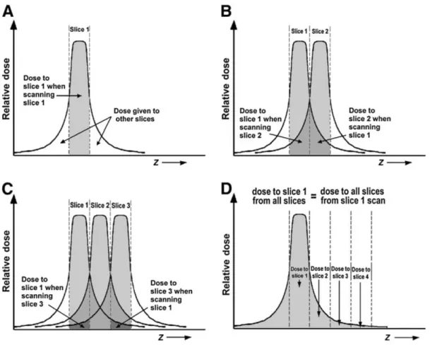
Although an IC measurement can easily determine the dose that the adjacent slices receive from one slice, the dose that the one slice receives from its adjacent slices is the one that really matters. This value corresponds to the CTDI, which can be defined as the integral dose value in a slice [35]. The concept of CTDI is explained in Figure 2.2.
Figure 2.2: Set of four figures illustrating the concept of CTDI.A:Dose received by slice 1 from the scan of slice 1.B:The dose received from slice 1 from the scan of slice 2 is equal to the dose received by slice 2 from the scan of slice 1. C:The dose received from slice 1 from the scan of slice 3 is equal to the dose received by slice 3 from the scan of slice 1. D:
The dose received by slice 1 from the scan of all slices is equal to the dose received by all slices from the scan of slice 1. This dose value corresponds to the CTDI [35].
The concept and measurement of the CTDI were proposed and established by the Food and Drug Administration (FDA) in the United States of America. [Shope 1981] The CTDI is measured in standard, cylindrical phantoms, constituted by PMMA. The phantoms are typically 15cm long and 16 or 32cm in diameter for head and body phantoms, respectively. When measuring dose values in the phantoms, an IC, typically 100mm long, is inserted
2 . 4 . F U N DA M E N T S O F D O S I M E T RY
in each of the phantom’s orifices. CTDI may then be calculated as is shown in the next equation, whereD(z) is the dose distribution along the z axis andxrefers to the phantom
orifice in which the dose is measured [20], [36].
CT DI100,x=
Z +50mm
−50mm
D(z)dz [Gy] (2.11)
Since CTDI value may vary significantly in the range of the phantom’s diameter (dose values would be higher in the periphery than in the center), necessity arose for the Weighted Computed Tomography Dose Index (CTDIW). This value is calculated using IC measured values from the phantom’s center (c) and periphery (p) [35].
CT DIW = 2
3CT DIp+ 1
3CT DIc (2.12)
In the early 2000s the concept of CTDI was questioned, due to the introduction of wider CT detectors. The new collimation widths were near or exceeded the length of the standard CT IC, 100mm. In this situation, primary radiation would not be considered completely and the scattered radiation would contribute only partially [20]. In 2007, Boone et al. showed that CTDI values measured with a standard IC (10cm long) on a PMMA phantom (15cm long) are underestimated, when compared to those measured on a phantom of infinite length. The ratio of CTDI100to the limit value for infinite phantom
length was found to be approximately constant up to 40mm collimation, though it greatly declines for wider collimation [37]. Another investigation, performed by Perisinakis et al., discovered that the CTDIW measured using a 100mm IC on the standard head and body phantoms were 15% and 27% lower, respectively, than CTDIW values measured in a 45cm long phantom. This study also stated that the minimum length of the IC and PMMA phantoms for an accurate determination of CTDIW is 50cm [38].
Two solutions were proposed for wide collimations. The American Association of Physicists in Medicine (AAPM) considered the use of extended phantoms, either one single 50cm long phantom or three phantoms in a row, with 30cm each. Measurements could be made using a standard IC and table translation [39]. The other solution is to in-crease the length of the IC. In 2010, the International Electrotechnical Commission (IEC) confirmed the existing CTDI principles for collimation widths not wider than 40mm, introducing a correction factor (measured with a 300mm IC ) to the CTDI definition for wider collimations [20]. The dosimetric parameters previously presented assume an exam with contiguous slices, where slice spacingIequals slice thickness,T. For helical
CT, the quantity analogous to slice spacing is the pitch, P. The pitch corresponds to
the quotient between the table movement per 360º gantry rotation,I, and nominal slice
thickness,N T.
P = I
N T (2.13)
C H A P T E R 2 . T H E O R E T I CA L F U N DA M E N T S
spacing provoking overlap between x-ray beams from adjacent rotations). To account for the effect of pitch in a helical exam dose and, for axial scans, to account for when when
slice spacingIdiffers from slice thicknessT, the quantity Volume Computed Tomography
Dose Index (CTDIvol) was introduced:
CT DIvol=
CT DIW
P (2.14)
The value of CTDIvolis required for each CT scan, and it should be provided by the manufacturer and presented on the scanner console. The problem with CTDIvolis that it neither takes patient size and cross section into consideration, nor the length of the irradiated volume. One indicator that is proportional to the length of the irradiated volume is the Dose-Length Product (DLP), represented in the next equation, whereLis
the total z-direction length of the scan.
DLP=CT DIvolL (2.15)
Though the DLP is a parameter proportional to the total deposited energy in the patient, it is not an adequate risk indicator, due to not accounting for the radiosensitivity of the irradiated tissues. For that purpose, the parameter effective dose, E, should be
used [35]. Effective dose can be calculated by multiplying DLP by k-factors, which are
conversion coefficients specific to each type of organ and tissue (more information in
section 3.3) [35], [20].
The CTDI and DLP concepts have greatly dominated CT dosimetry, being standard quantities for various tasks, such as acceptance and quality testing of CT apparatus and comparisons between CT scanners and protocols. Still, both CTDI, CTDIvoland DLP can only offer rough estimates of the patient dose levels involved. Since they are determined
for cylindrical PMMA phantoms, they cannot match the patient situation well. Patient-specific dose estimates taking into account patient dimensions, cross section and anatomy, would be preferable [20].
Chapter
3
D o s e E s t i m a t e s i n t h e Pa t i e n t
In diagnostic radiology, the radiation dose to the healthy tissues could be a burden and should always be minimized. Therefore, the radiological protection scientific com-munity has shown continuous interest in finding more practical and accurate methods to estimate dose. Over the last 50 years the use of models of human anatomy to calculate radiation dose has grown exponentially. Accurate radiation dosimetry in the human body is inherently challenging due to several reasons:
• Exposure scenarios vary and may include complex geometrical relationships be-tween the source and the human body;
• An exposure can involve multiple radiation types, each traversing the human body and interacting with tissues differently;
• The human body consists of various heterogeneous anatomical structures, with varying density, size, shape and radiosensitivities. Additionally, these anatomical structures are subject to organ motion.
In radiation dosimetry anatomical models are of vital importance because dose inside a living person cannot usually be directly measured. A phantom can be defined as a phys-ical or computational device that mimics human anatomy. It has been established that dose inside the body can be calculated using either a physical or computational phantom. The accuracy of any estimate always greatly depends on the anatomical models repre-senting the specific geometry and radiation attenuation characteristics of each individual [40].
C H A P T E R 3 . D O S E E S T I M AT E S I N T H E PAT I E N T
is also reported. Finally, some techniques using computational phantoms to provide organ dose estimates are presented.
3.1 Dose Estimates using Physical Phantoms
Physical phantoms are constituted of solid materials that, from a radiological point of view, are equivalent to human tissues. The human body consists mainly of water, so materials such as water or perspex (PMMA) are common constituents of physical phantoms. These phantoms are standardized, have simple designs and are helpful for routine quality assurance measurements and comparing CT scans radiation output levels [40].
The AAPM report 204 proposed SSDE, a method to estimate patient dose to account for patient size, grounded on the principle that the CTDIvol value presented by the CT scanner is not accurate and can vary according to patient diameter. For example, when CTDIvolis measured in a phantom with 32 cm in diameter, then dose would be higher for patients whose diameters are smaller than 32cm and lower for patients whose diameters are bigger than 32cm. Though this trend is predictable, the calculation of numerical correction values is quite complex [20], [22]. Therefore, since in pediatric examinations the CTDIvolprovided by the scanner can be about four times smaller than the real dose value, the investigation and determination of correction factors is very important [41].
The AAPM report includes several tables of conversion factors,f, for the 16 and 32cm
standard PMMA phantoms, depending on four possible anthropomorphic parameters based on patient diameter: Lateral Diameter (L), Anterior-Posterior Diameter (AP), L+AP and effective diameter. The formula to estimate patient dose for a specific patient size is:
SSDE=CT DIvolxf (3.1)
The extensive tabulations in the AAPM report are based on a compilation of concor-dant data coming from different sources: (1) physical measurements using
anthropomor-phic phantoms; (2) physical measurements using cylindrical PMMA phantoms; (3) Monte Carlo measurements using voxilized phantoms; (4) Monte Carlo measurements using sev-eral cylindrical phantoms [22]. Nevertheless, measuring patient diameter is not a trivial task. The main drawback of this method is the difficulty with the consistent measurement
of patient diameters, which may vary according to its anatomical variability [20].
Anthropomorphic physical phantoms better resemble the anatomy of the human body and can represent the entire body or only part of it. They are usually comprised by several tissue-equivalent materials shaped to resemble body organs or bones. The anthropomor-phic phantoms for external radiation dosimetry applications have cavities in locations that match with organs of interest. This way, tiny dosimeters can be inserted in different
locations of the phantom to measure radiation doses from external sources [40], [42]. The
3 . 2 . D O S E E S T I M AT E S U S I N G C O M P U TAT I O N A L P H A N T O M S
main examples for this type of phantom are the RANDO phantom by the Phantom Labo-ratory and the ATOM phantom developed by CIRS, Inc. One of the primary downsides to this type of phantoms is the limited number of body sizes that cannot entirely reflect the human population variability [40].
3.2 Dose Estimates using Computational Phantoms
The determination of organ doses via computational phantoms and calculations be-came feasible with the advent of first-generation computers and simulations using MC methods. These phantoms were extensively detailed, containing information about exte-rior and inteexte-rior features of the human body, such as shape, density, volume and chemical composition of various organs and tissues. In the 1980s, due to the advent of personal computers and the possibility to visualize anatomy in 3D through medical imaging, com-putational phantoms became common and widely used by the radiological community.
There are three different computational phantom generations that can be clearly
distinguished: (1)Stylized phantoms (1960s to 2000s); (2)Voxel phantoms (1980s to present);(3)Boundary Representation (BREP) phantoms (2000s to present). Figure 3.1 contrasts these three computational phantom generations [40].
C H A P T E R 3 . D O S E E S T I M AT E S I N T H E PAT I E N T
3.2.1 Stylized Phantoms
The first generation of computational phantoms arose with the purpose of providing better dose estimates from internally deposited radioactive materials for workers and patients [40].
The first phantom in this generation originated in the 1960s with the work of Fisher and Snyder at the Oak Ridge National Laboratory (ORNL) [43]. This phantom, called Fisher and Snyder adult phantom, was developed through the use of Constructive Solid Geometry (CSG) techniques, which were the base of development for all of the phantoms in this generation. The CSG method uses boolean operators to combine various primi-tive shapes such as spheres, cones, prisms or cuboids, which can be described by cuboid equations, to create a model of human anatomy. The phantom was assumed to be consti-tuted homogenously by tissue [40]. Although the original purpose of the phantom was to work with internal dosimetry, a study used the phantom to determine dose distributions from external sources of gamma rays [43]. In 1969, the first heterogeneous phantom, the MIRD-5 (Medical Internal Radiation Dosimetry) phantom, was published. The phantom was comprised of three types of tissue: lung, skeletal and the rest was homogenous soft tissue. The MIRD-5 intended to represent the ‘reference man’, a healthy male with av-erage dimension that had been defined by the ICRP publication nº 23 [40], [44]. Some attempts were also made by Fisher and Snyder to develop stylized pediatric phantoms of various ages, referred to as ’similitude’ children phantoms.
The first generation of computational phantoms provided crude and anatomically inaccurate phantoms because organ shape and location is quite complex and cannot be accurately described by a limited set of surface equations. By the end of the 1980s sub-stantial efforts were directed to the development more anatomically realistic phantoms
[40].
3.2.2 Voxel Phantoms
The creation and evolution of medical imaging techniques, such as CT and Mag-netic Resonance Imaging (MRI) allowed for the 3D visualization of anatomical internal structures and paved the way for the development of voxel (also known as tomographic) phantoms. Voxel phantoms, which could more accurately describe human anatomy, were essentially based on three types of anatomical images: CT and MRI images of live subjects, and cross sectional images of cadavers. Voxel phantoms are models of the human anatomy consisting of several voxels (3D pixels) grouped together to model several anatomical structures. Since a voxel is a cuboid, tomographic phantoms are also based on CSG methods [40].
It is widely believed the first image-based phantom for radiation dosimetry was de-veloped by Gibbs et al. to assess patient dose during dental radiological procedures [45]. In the late 1980s a research team in Germany used 3D CT imaging to create the GSF
3 . 2 . D O S E E S T I M AT E S U S I N G C O M P U TAT I O N A L P H A N T O M S
(National Research Center for Environment and Health, Institute of Radiation Protec-tion) family, a family of 12 voxel phantoms composed by an adult male, an adult female, pediatric and pregnant woman phantoms [40]. Posteriorly, two of the adult phantoms belonging to the family previously mentioned, GOLEM and LAURA, suffered several
modifications to become the REX and REGINA phantoms. The ICRP male and female reference phantoms have the same anatomy as REX and REGINA, but updated elemental tissue composition. The anatomical data of both phantoms was adjusted to the ICRP data with high precision. The number of organs and tissues identified in each phantom was 140, which could be assigned to 53 different materials [46]. The ICRP reference phantoms
helped the standardization of phantom-based radiation dosimetry with realistic voxel phantoms, which was a real need in the radiation dosimetry field at the time. However, due to relatively large slice thicknesses (8mm in the reference male and 4.84mm in the reference female) [40], [46], there were some issues with the anatomical accuracy of the phantoms, such as the unrealistic definition of smaller organs and the skin and walled organs were reported to contain small holes [40].
The first phantom based on cross sectional color images of a cadaver, assembled by more than 4.7 billion voxels, was the VIP-Man (Visible-Photographic Man), whose cross sectional image is compared to one from a stylized phantom in Figure 3.2 [40]. Since this generation of computational phantoms had few pediatric phantoms to help with dose assessment during pediatric diagnostic and therapy examinations, researchers at the University of Florida (UF) constructed a set of pediatric voxel phantoms, divided in two series: Series A and Series B [47].
C H A P T E R 3 . D O S E E S T I M AT E S I N T H E PAT I E N T
The shift from the first to the second generation of computational phantoms was initially boosted by the voxel phantoms’ improved anatomical realism. By 2014 a total of 85 different voxel phantoms had been developed all over the world. Nevertheless, there
were some issues related to the development and usage of voxel phantoms. The voxel size is a very important one. While some authors seem to think that a voxel resolution in x,y and z of 2x2x2mm can represent human anatomy fairly accurately, it is not small enough to delineate some minor and very radiosensitive organs, such the bone marrow [40]. However, while a smaller voxel allows better anatomical fidelity, it also boosts the number of voxels in the phantom, which increases the computational effort during MC
simulations. Therefore, there has to be a compromise between anatomical fidelity and the number of voxels.
3.2.3 BREP Phantoms
A BREP phantom is created using a tomographic image set, by acquiring the surface contours of the organs and tissues and later assembling them into a whole body model. Instead of voxels, the organ surfaces are defined by NURBS (Non-Uniform Rational Basis Spline) or polygon mesh surfaces. The main advantages of BREP are its ability to model complex anatomical details and surface deformation, which makes it ideal for tasks such as adjusting organ size, modeling organ motion and simulating the interactions of hu-mans to the environment by varying the phantom posture [40].
Hybrid phantoms (combining voxel and BREP geometries) are thought of as the fu-ture, given their ability to represent some structures using BREP techniques and other structures, in which boundary representation is too heavy, can be modeled using voxels, this way taking the best of each generation. Since the 2000s the world has seen the interest in hybrid phantoms greatly increasing, existing nowadays a variety of hybrid phantoms families [40], [48].
3.3 Patient and Organ Dose Estimates Using MC Methods and
Computational Phantoms
Modern MC method codes are able to model the CT scanner’s geometry, as well as the interactions of radiation with matter. When coupled with standard phantoms, such as the ones provided by ORNL, ICRP or UF, MC dose estimation methods are considered very accurate [49].
In the 1990s, the European Commission directed significant efforts to the estimation
of patient dose in CT. The primary approach intended to calculate effective dose, by using
the DLP and CTDIin−air values for calibration purposes. The DLP would be multiplied by
conversion coefficients specific to each body part, known as k-factors [20]. This concept,
only used in standard phantoms, is extensively used in the scientific community, with widely available conversion coefficients covering both genders, as well as a variety of
3 . 3 . PAT I E N T A N D O R GA N D O S E E S T I M AT E S U S I N G M C M E T H O D S A N D C O M P U TAT I O N A L P H A N T O M S
ages, such as adults, children and newborns [20], [50]. This technique suffers from some
drawbacks, such as the ambiguous choice of body region and the broad use of the same k-factors in all CT scanners. Additionally, effective dose values are only rough estimates,
being specific to the phantom and not the patient because CTDI only represents the scanner output [20]. Moreover, this method does not allow the assessment of organ dose values, one of the main quantities of interest for risk evaluation [49].
The necessity for organ dose estimates led to the development of several programs, such as ImPact and CT Imaging. This type of software relies on computational phantoms, coupled with input parameters of the CT scan and pre-calculated tables of dose contribu-tion to each organ, to provide effective and organ dose estimates [20]. The pre-calculated
tables of organ dose conversion coefficients exist for various phantoms, such as the ICRP
male and female reference phantoms, and are age and gender specific [51], [52]. Though this technique is phantom specific, it can be quite useful for studying the influence of certain parameter settings on the CT scanner on patient dose [49]. It is necessary to point out that the anthropomorphic models of the aforementioned techniques rely on the ages and sizes of average individuals, not taking patient size and anatomy into account. This issue may lead to substantial errors in the assessment of organ and effective dose [49].
In 1992, Veit et al. studied the influence of patient size on organ doses in diagnostic radiology. The voxel size of the BABY phantom from the GSF family was modified in one or more dimensions and organ dose conversion factors were calculated. The study concluded that only the dimension in the direction of the irradiation has a relevant effect
on the organ dose conversion factors and that the effect can be very different for various
organs [53]. Caon et al. scaled the voxel model ADELAIDE in size by ±5%. Results showed that effective dose to the chest, abdomen and whole torso values tend to drop for
phantoms with higher voxel volume [54]. Thus, using this approach a voxel model can be scaled to more accurately represent individual patients [55].
In 2009, Segars et al. attempted what is believed to have been the first attempt to create patient specific phantoms. The method used a deformation algorithm to transform a NCAT (NURBS-based Cardiac-torso) adult phantom, which uses BREP type surfaces, into a child model [56]. Similar methods were later used and adapted by other authors to generate whole body models of adult and pediatric patients [57], [58]. Although this type of approach has showed some promising results, it requires demanding manual labor and is very heavy computationally [49]. A study performed by Bueno et al. performed geometrical deformations on a tomographic phantom by aligning the pelvic and thoracic portions of the phantom with the geometries of patient CT images [59]. The phantom considered was MAX, a voxel phantom developed by Kramer et al. [60].
C H A P T E R 3 . D O S E E S T I M AT E S I N T H E PAT I E N T
1. The patient CT data is used to acquire information on patient and organ size and shape in the scanned region.
2. The best fitting computational phantom is chosen by comparing lateral, anterior-posterior and effective diameters. The patient CT data are then appended at the top
and bottom of the scanned volume with the rest of the corresponding phantom to construct a whole body phantom.
3. 3D dose distributions are calculated for the whole body models.
4. Organ dose is calculated inside Volumes of Interest (VOIs), defined as ellipsoid or half-ellipsoid shapes that overlap with the organs, by adding the dose values to all voxels in organ VOIs [20], [49].
During these studies, the AP and L diameters of the patients did not always match the ones of the best-fitting computational phantom, so the phantoms could be scaled or wrapped in fat-equivalent tissue layers to create slim or overweight models. Within the scope of these studies, it is important to mention that the use of whole body models instead of only the scanned range model is of primary importance when calculating dose values (represented in Figure 3.3), in order to account for: (1) scattered radiation to organs located outside the scanned region, which may still receive a significant amount of radiation; (2) backscattered radiation originated in the neighboring areas, which raises dose in the scanned region. Moreover, Kalender et al. stated that lung dose during a lung scan accounts for 10% to 50% of the total dose in the imaged volume, which makes the lungs a primary organ of concern when considering CT dose.
The use of VOIs to assess organ dose is justified by three assumptions made by the authors:
1. Organ dose values depend more on patient size and organ cross-section and chemi-cal composition than on organ shape;
2. Dose distributions are relatively homogenous and organ dose values are not criti-cally dependent on covering the complete organ;
3. Accurate segmentation of organ contours is a distinct and non trivial issue, par-ticularly for routine clinical applications, though there have been developed some working solutions for larger organs, such as the lungs or liver [49].
However, this approach has some drawbacks, it is possible that not accounting for the whole volume of a given organ does not provide accurate dose measurements. Moreover, given the lack of contrast between some soft tissues in a CT image, the use of existing widely used reference phantoms with the adaptation of only some interest organs to the patient’s anatomy could provide more accurate organ dose values. Since this kind of approach may be too demanding for routine clinical use, the development of a technique,
![Figure 1.1: Trends in the annual frequency of diagnostic x-ray examinations in function of health care level [1].](https://thumb-eu.123doks.com/thumbv2/123dok_br/16537671.736603/28.892.140.756.398.758/figure-trends-annual-frequency-diagnostic-examinations-function-health.webp)
![Figure 2.1: Alan MacLeod Cormack (left) and Godfrey Newbold Hounsfield (right) are the co-creators of Computed Tomography [26].](https://thumb-eu.123doks.com/thumbv2/123dok_br/16537671.736603/36.892.202.692.681.1022/macleod-cormack-godfrey-newbold-hounsfield-creators-computed-tomography.webp)
![Table 4.1: Main characteristics of the ICRP male and female reference phantoms. Adapted from [66].](https://thumb-eu.123doks.com/thumbv2/123dok_br/16537671.736603/60.892.187.706.206.451/table-main-characteristics-icrp-female-reference-phantoms-adapted.webp)