FACULDADE DE
ENGENHARIA DA
UNIVERSIDADE DO
PORTO
Acceleration of a Stereo Navigation
Application for Autonomous Vehicles
João Diogo Vilela Teixeira
Master in Electrical and Computer Engineering Supervisor: José Carlos dos Santos Alves, PhD Co-supervisor: João Paulo de Castro Canas Ferreira, PhD
Resumo
Ao longo dos últimos anos, sistemas de processador embebido têm vindo a ser cada vez mais utilizados em aplicações nos mais diferentes campos. Algumas dessas aplicações são demasiado exigentes em termos temporais para serem executadas unicamente por estes processadores. De forma a aliviar a carga de processamento, blocos de hardware dedicados podem ser acoplados ao processador para auxiliar no processamento de zonas da aplicação que sejam computacionalmente mais intensivas.
Nesta dissertação, o principal objectivo foi acelerar uma aplicação de terceiros, originalmente em linguagem C, preparada a executar num processador convencional. A aplicação a acelerar está direccionada para um sistema de navegação estéreo onde, através do processamento de imagens vindas de duas câmaras, um veículo autónomo poderá inferir a sua posição, rotação e translação relativas. O objectivo de acelerar esta aplicação está inserido no projecto Europeu REFLECT.
Para o desenvolvimento deste trabalho foram identificadas três das funções que consumiam mais tempo relativo de execução da aplicação num processador PowerPC 440 a 400MHz. Uti-lizando a ferramenta de síntese de alto nível Catapult C, foram criados três módulos de hardware para substituir essas mesmas funções. Os módulos criados foram finalmente implementados numa FPGA da Familia Virtex-5 da Xilinx e executados a 100MHz.
Foi criado um sistema híbrido hardware/software onde as zonas computacionalmente mais criticas foram executadas pelos blocos de hardware criados enquanto o resto da aplicação contin-uou a ser executado como software. Ao usar estes módulos de hardware para auxiliar a aplicação executada pelo processador PowerPC 440, conseguiu-se uma aceleração de cerca de 1,5 vezes quando comparada com a mesma aplicação executando exclusivamente sob a forma de software no processador.
Abstract
Throughout the years, embedded processor systems are becoming more and more used for applications in the most diverse fields. There are however some applications that are too time demanding to be executed solely by a standalone embedded processor. To relieve some of the processing load, dedicated hardware blocks can be coupled to the processor aiding it by processing the parts of the application that are, computationally speaking, more intensive.
The main objective of this thesis was to hardware accelerate a third party C-language applica-tion that was aimed to execute in a general purpose processor. The applicaapplica-tion to be accelerated is aimed for a stereo navigation system where, through image processing of data coming from two cameras, an autonomous vehicle could infer its relative position, rotation and translation. The objective to accelerate this application is inserted into the European REFLECT project.
In this thesis, the three functions that consumed most of the application’s time were identified when executed in an PowerPC 440 processor at 400MHz. Using the high level synthesis tool Catapult C, the corresponding modules that would replace this three functions were created. These modules were synthesized in a Xilinx Virtex-5 FPGA and executed at 100MHz.
It was created an hardware/software hybrid where the most computational intensive functions were carried by the hardware blocks, being the rest left to be carried by the processor. Using these hardware modules to aid the application that was executed by the PowerPC 440 processor, a speed-up of 1,5 times was achieved when compared to the same application being carried solely as software by the processor.
Agradecimentos
Agora que uma etapa importante da minha vida chega ao fim, gostaria de aproveitar esta opor-tunidade para agradecer a algumas pessoas, sem as quais não seria possível chegar onde cheguei hoje.
Queria em primeiro lugar, agradecer ao meu orientador, professor Dr. José Carlos dos Santos Alves e ao meu co-orientador, Professor Dr. João Paulo de Castro Canas Ferreira, pela opor-tunidade de trabalhar num projeto tão desafiante e motivador, bem como, toda a sua ajuda dis-pendida.
Queria também agradecer aos meus colegas da sala I224 do departamento de Engenharia Eletrotécnica e Computadores da Universidade do Porto, que contribuíram para um excelente ambiente: Duarte Azevedo, Helder Campos, Eng. João Gonçalves, João Santos, Nuno Paulino, Pedro Carneiro, Ricardo Pereira, Tiago Campos e especialmente ao Eng. Eduardo Sousa por toda a sua ajuda e partilha de informação no decorrer do trabalho.
Por fim, não poderia deixar de dedicar um agradecimento muito especial à minha família, os principais responsáveis pela pessoa em que me tornei hoje e pelos caminhos que segui para estar onde estou. Ao meu irmão, por toda a sua ajuda e apoio mesmo quando as coisas correm mal quando não deviam. À minha mãe, por ser uma constante fonte de inspiração e a quem dedico este trabalho; por todo o seu apoio e grande espírito de sacrifício, que conseguiu fazer com que nunca nada me faltasse mesmo quando tal não parece possível e sem a qual tenho a certeza que não seria possível chegar tão longe. Ao meu pai, por me ensinar que devo sempre acreditar em mim sobre todas as outras coisas e por ser um modelo inalcançável a seguir.
A todos, o meu muito obrigado.
João Diogo Vilela Teixeira
“The winner ain’t the one with the fastest car, it’s the one who refuses to lose.”
Dale Earnhardt
Contents
1 Introduction 1
1.1 Motivation and objectives . . . 1
1.2 Work Procedure . . . 2
1.3 Thesis Structure . . . 2
2 State of the Art 5 2.1 Hardware Acceleration . . . 5 2.1.1 Hardware Alternatives . . . 6 2.1.2 Hardware Techniques . . . 9 2.1.3 Architecture Alternatives . . . 10 2.2 High-Level Synthesis . . . 12 2.3 Tools . . . 14 2.3.1 Virtex-5 . . . 14 2.3.2 PowerPC 440 . . . 15 2.3.3 Catapult C . . . 17 2.3.4 Other Tools . . . 18
3 Analysis of the Stereo Navigation Application 21 3.1 Application Overview . . . 21
3.2 Porting the Application . . . 23
3.2.1 Installing the Kernel . . . 24
3.2.2 Cross-Compiling the Application . . . 25
3.3 Profiling the Application . . . 27
3.3.1 Profiling With No Optimization . . . 28
3.3.2 Profiling With the -O1 Optimization Flag . . . 29
3.3.3 Profiling With the -O2 Optimization Flag . . . 29
3.3.4 Profiling With the -O3 Optimization Flag . . . 30
3.3.5 Profiling in the Computer . . . 30
3.4 Analysis of the Critical Functions . . . 31
3.4.1 ConvConst . . . 33
3.4.2 ConvRepl1 . . . 35
3.4.3 ConvRepl2 . . . 35
3.5 Conclusions . . . 36
4 Creating the Hardware Modules 37 4.1 Catapult C . . . 37
4.2 Solutions . . . 40
4.2.1 Fixed-point With 32 Bits . . . 41
4.2.2 Fixed-point With 64 Bits . . . 41
4.2.3 Soft Floating-point With 32 Bits . . . 43
4.2.4 IP-Cores . . . 46
4.3 Creating the ConvConst Module . . . 47
4.4 Creating the ConvRepl1 Module . . . 50
4.5 Creating the ConvRepl2 Module . . . 51
4.6 Conclusion . . . 51
5 Module Design 53 5.1 The Target Modules . . . 55
5.1.1 ConvRepl1 and ConvRepl2 . . . 56
5.1.2 ConvConst . . . 58
5.2 DPRAM Module . . . 59
5.3 The user_logic Core . . . 61
5.4 Software-Hardware Interface . . . 64
5.4.1 Profiling the Application . . . 66
5.5 Improving the Hardware Acceleration . . . 69
5.5.1 Memory Mapping . . . 70
5.5.2 Memory Sharing . . . 70
5.5.3 Including the Constant Values Inside the Modules . . . 72
5.5.4 Using Parallel Modules . . . 73
5.6 Comparing the Hardware Solutions . . . 75
6 Conclusion 79 6.1 Conclusion . . . 79
6.2 Future Work . . . 80
A Appendix 81 A.1 Output of the Original Application . . . 81
A.2 Output of the Application Using the 32-bit Fixed-point Solution . . . 82
A.3 ConvConst module . . . 83
A.4 Memory Organization . . . 84
A.5 Configure the Powerpc Linux Kernel in the Xilinx ML507 Development Platform 85
List of Figures
1.1 Work flow. . . 4
2.1 DSP48E slice. . . 8
2.2 Different interconnect configurations. Fine-grained on the left and coarse-grained on the right. . . 8
2.3 Execution of an instruction without pipelining. . . 9
2.4 Execution of an instruction with pipelining. . . 9
2.5 Various Processor-FPGA architectures (adapted from[1]). . . 11
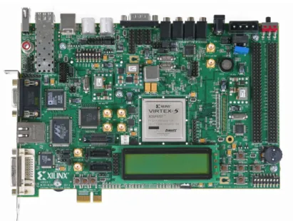
2.6 ML507 development board. . . 16
2.7 Catapult C process flow. . . 18
3.1 Example of image distortion caused by the camera lenses. In this case the Barrel distortion. . . 22
3.2 Detection of an obstacle, as well as, speed, translation and rotation of the vehicle by the application. . . 23
3.3 Kernel making the bridge between hardware and software. . . 24
3.4 Example of the addresses given by XPS to each of the cores. . . 25
3.5 Hardware accelerating the application (on the right) vs software-only implemen-tation (on the left). . . 27
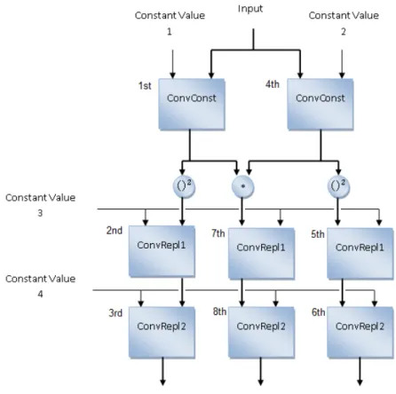
3.6 Dataflow of the application. . . 33
3.7 Input data of the ConvConst model. . . 34
4.1 Start and done handshake signals. Taken from [30]. . . 38
4.2 Differences in architecture designs when using a RAM memory for data storage (left side of the figure) and using individual registers (right side of the figure). . . 39
5.1 Architecture of the core to be implemented (in dashed line) as well its interface with powerPC via PLB. . . 54
5.2 Core’s interface diagram (left ports are inputs, right are outputs). . . 55
5.3 Interface representation of the ConvRepl1 module (left ports are inputs, right are outputs). . . 56
5.4 Waveform for some of the ConvRepl1 module’s outputs . . . 57
5.5 Waveform for some of the ConvRepl1 module’s outputs (the image was com-pressed for readability reasons). . . 58
5.6 Waveform for some of the ConvConst module’s outputs. . . 59
5.7 RAM’s port connections (left ports are inputs, right are outputs). . . 60
5.8 Example of one RAM organization. . . 61
5.9 Interface between a module and the DPRAM. . . 62
5.10 Example of how the DPRAM6 is enabled. . . 62
5.11 RAM shared by ConvRepl1 and ConvRepl2. . . 71
5.12 Data and timeflow of the hardware solution making use of parallel modules. . . . 75
5.13 Flowchart of the software control operations. . . 76
A.1 Interface representation of the ConvConst module (left ports are inputs,right are outputs). . . 83
A.2 Memory organization for the user_logic core. . . 84
A.3 Software platform settings. . . 86
List of Tables
3.1 Profiling with no optimization in the PowerPC processor (ten executions). . . 28
3.2 Profiling with the -O1 optimization in the PowerPC processor (ten executions). . 29
3.3 Profiling with the -O2 optimization in the PowerPC processor (ten executions). . 29
3.4 Profiling with the -O3 optimization in the PowerPC processor (ten executions). . 30
3.5 Profiling with no optimization in the PC (ten executions). . . 30
3.6 Profiling with the -O1 optimization in the PC (ten executions). . . 31
3.7 Profiling with the -O2 optimization in the PC (ten executions). . . 31
3.8 Profiling with the -O3 optimization in the PC (ten executions). . . 31
4.1 Timimg results for the mymult module (32-bit multiplication). . . 42
4.2 Timing results for the mymult64 module (64-bit multiplication). . . 42
4.3 Profiling results for the ConvConst using the soft floating-point solution (ten exe-cutions). . . 44
4.4 Profiling results for the ConvRepl1 using the soft floating-point solution (ten exe-cutions). . . 44
4.5 Profiling results for the ConvRepl2 using the soft floating-point solution (ten exe-cutions). . . 45
4.6 Profiling results of the application using the soft floating-point solution (ten exe-cutions) . . . 45
4.7 Timimg results for the soft floating-point multiplication . . . 45
4.8 Timimg results for the soft floating-point addition . . . 46
4.9 Execution time for the multiplication and addition process for different approaches. 47 4.10 Profiling results of the Convconst function using int data types running on the PowerPC (ten executions). . . 48
4.11 Results of the Catapult report referring the ConvConst module. . . 49
4.12 Frequency obtained for the ConvConst module in XST. . . 49
4.13 Throughput time obtained for the module ConvConst. . . 50
4.14 Results of the catapult report referring the convRepl1 module. . . 50
4.15 Throughput time obtained for the module convRepl1. . . 50
4.16 Results of the catapult report referring the convRepl2 module. . . 51
4.17 Throughput time obtained for the module convRepl2 . . . 51
5.1 Address of each RAM in the user_logic module . . . 61
5.2 Address of each RAM of the ConvConst module. . . 63
5.3 Register interface with the modules. . . 63
5.4 Relative speed-up obtained by the ConvConst hardware module when compared with its software homologous (ten executions). . . 67
5.5 Relative speed-up obtained by the Convrepl1 hardware module when compared with its software homologous (ten executions). . . 67
5.6 Relative speed-up obtained by the Convrepl2 hardware module when compared with its software homologous (ten executions). . . 68
5.7 Total execution time of the application making use of hardware modules (ten exe-cutions). . . 68
5.8 Total time spent to read and write to the core’s memories (ten executions). . . 68
5.9 Relative execution time of the solutions found (ten executions). Time in seconds. 69
5.10 Comparison of the total execution time of the StereoNav application with and without memory mapping (ten executions). . . 70
5.11 Comparison of the total execution time of the StereoNav application with 6 and 5 memories (ten executions). . . 71
5.12 Throughput time obtained for the modules using internal constants. . . 72
5.13 Comparison of the total execution time of the StereoNav application with five memories and the constant h values inside the hardware modules as opposed to the application making use of six memories (ten executions). . . 73
5.14 Relative execution time of the solutions making use of the included constants (ten executions). . . 73
5.15 Relative execution time of the solutions found using the hardware modules in par-allel (ten executions). . . 77
5.16 Comparison of the place and route characteristics, in a Virtex-5 FPGA, for the four solutions found. . . 77
Abbreviations
ASIC Application-Specific Integrated Circuit CPU Central Processing Unit
DPRAM Dual-Port Random Access Memory EDK Embedded Development Kit ELDK Embedded Linux Development Kit FPGA Field Programmable Gate Array FPU Floating-Point Unit
GPU Graphics Processing Unit HDL Hardware description language HLS High Level Synthesis
IC Integrated Circuit IP Intellectual Property
ISE Integrated Synthesis Environment kB kiloByte
lsb Least significant bit LUT Look-Up Table MHz Mega Hertz msb Most significant bit nm Nanometer
PAR Place And Route PLB Processor Local Bus
PowerPC Performance Optimization With Enhanced RISC – Performance Computing PPC440 PowerPC 440
RAM Random Access Memory
REFLECT Rendering FPGAs to Multi-Core Embedded Computing RISC Reduced Instruction Set Computing
RTL Register Transfer Level XPS Xilinx Platform Studio XST Xilinx Synthesis Technology
Chapter 1
Introduction
With the advances in IC technology, more transistors can be arranged in a smaller area resulting in more and more processing power at lower costs. With this constant evolution, one type of hardware is becoming widely used for prototyping and final product implementation, that is the case of Field Programmable Gate Arrays (FPGA). This type of hardware can be reconfigured by a programmer "in the field" to do a specific functionality, having a flexibility similar to software programming making them preferable to the more static ASIC implementation when facing low volume applications. The possibility that these systems have of being customized allows them to be specialized to perform the operation that they were tailor-made for, and thus makes them able of achieving better performance than conventional computing systems.
A field that is gaining interest is the hardware acceleration of software applications like image processing, data streaming, signal processing and other computational intensive applications. A large community of software developers, usually makes use of C-language based programming to provide the embedded systems with the desired behaviour. However, for cases where performance, timing, power or area constrains are strict, custom hardware to optimize the performance can be the only solution. Two approaches can be followed, depending on the application at hand, to create a system that obeys to the constraints imposed: create a custom hardware device to execute all the application or divide the system in two parts where the most critical parts are handled by dedicated hardware while the rest is executed by software.
1.1
Motivation and objectives
The objective of this thesis is to hardware accelerate a stereo navigation application, making use of reconfigurable hardware modules of a Virtex-5 FPGA, in order to be apt for an efficient use in autonomous vehicles. The stereo navigation application to be accelerated (with C source code provided by Honeywell [2]), is intended to be integrated in an airplane localisation system, in case
that the GNSS1used is temporarily unavailable and the plane has to localise itself for some period of time.
The idea of the application is that from independent images derived from two cameras looking in approximately the same direction, dominant entities in the image, invariant to rotation and translation, can be extracted. With the cameras taking the pictures at the same time, this features can be localized in a three dimensional space. Images taken in adjacent instants can be used to calculate the vehicle’s rotation and translation. The thesis’s work is inserted in the European project REFLECT (Rendering FPGAs to Multi-Core Embedded Computing) [3].
These application is based on image processing which puts major demands on the processors. By making use of dedicate hardware blocks to process the image data, its expected to relieve the processor of the most intensive computations and obtain some degree of acceleration.
The parts of the applications that are consuming most of the time and are delaying the other parts (and the application itself) will be implemented in hardware, while the "lighter" parts will continue to execute in the PowerPC processor present in the development board that will be used during this thesis. With this approach, both software and hardware will be working together for a faster application.
1.2
Work Procedure
The basis of the proceeded work throughout this thesis had, as the main objective, to accelerate the stereo navigation application with as little as possible changes to the original source code ,i.e, no code optimization, no function inlining and no alterations that could, in any way, make the original application execute faster.
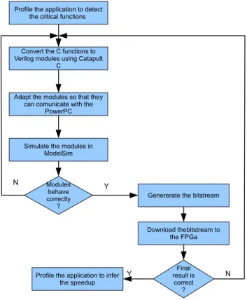
The work flow followed through the project can be seen in figure1.1.
1.3
Thesis Structure
After this chapter, the document is composed of five more chapters. In chapter 2, it is made a study of the State of the Art. The chapter is comprised by hardware acceleration solutions, technology options and the used tools for the development of the project.
Chapter 3presents an analysis of the application running in the ML507 development board. Composing this chapter is a detailed description of the application itself (functionalities, charac-teristics etc.), how the application was ported (reconfigured in order to run) to the development board and the detection of the slowest parts using some profiling techniques.
In chapter 4 it is made a description of how the hardware modules were developed using Catapult C, as well as, the main dificulties and the solutions found.
Chapter 5describes how the software-hardware interface was constructed. The required veri-fications are made along with some critical analysis of the obtained solutions.
1.3 Thesis Structure 3
Finally, chapter 6presents a conclusion of the thesis, as well as, some possible considerations for future work.
Modules behave correctly
?
Profile the application to detect the critical functions
Convert the C functions to Verilog modules using Catapult
C
Adapt the modules so that they can comunicate with the
PowerPC
Simulate the modules in ModelSim
Genererate the bitstream
Download thebitstream to the FPGa Final result is correct ? Profile the application to infer
the speedup
Y Y N
N
Chapter 2
State of the Art
2.1
Hardware Acceleration
Many of today’s applications, like data streaming, image processing, etc., are putting higher demands on computing devices. At the same time, production costs and time-to-market targets are getting more and more strict. Having a general computing device isn’t, normally, the best choice to process computational intensive algorithms because of the overhead caused by the instruction fetch, decode and execute cycle. General-purpose computing devices are designed to perform a wide variety of tasks with reasonable performance rather than having high performance on specific tasks. These devices are not well suited for applications that aim in executing one specific task with high degree of processing speed. Designing hardware blocks dedicated solely in the execution of these tasks provides a degree of specialization which gives place to higher performance degree.
The two main reasons why hardware can accelerate a given application is: parallelization and data flow direction. By making use of a parallel architecture, multiple operations can be executed at the same time. For instance, by parallelyzing the arithmetic operation D = (a + b) × (a − c), the addition and subtraction operations can be made at the same time while the multiplication would proceed in the following instant. This would not be possible in a general purpose processing unit where, the same operation would take three cycles (addition, then subtraction and, finally, multiplication) instead of the two cycles used in the hardware alternative. The second reason why an application is accelerated when executed making use of hardware blocks is, that by being able to organize all the functional units, it is possible to direct the data flow such that the maximum number of functional units are operating at the same time.
Applications where hardware acceleration can provide excellent results are the ones that re-quire:
• high processing power requirements ; • high bandwidth requirements ; • real-time constraints;
• data formats for which the general purpose CPUs are not optimized;
• hardware interface (example: digital camera interface).
One example where hardware acceleration was used, was the "Hardware acceleration of a Monte Carlo simulation for photodynamic therapy treatment planning". There, a TM-4 board with four FPGAs of the Stratix I family provided the hardware blocks to accelerate a Monte Carlo application based on the Monte Carlo for Multi-Layered media software. The hardware performed the MC simulation, on average, 80 times faster and 45 times more energy efficient than its software counterpart running on 3-GHz Intel Xeon processor[4].
2.1.1 Hardware Alternatives
To provide the required hardware acceleration, two main alternatives can be chosen: either use an Application-Specific Integrated Circuit (ASIC) or a Field-Programmable Gate Array (FPGA).
An ASIC is an IC designed specifically for a particular use, rather than general purpose use. Having the task to be carried well defined, the IC is designed to operate in the most efficient way. By specializing this IC, only the required logic is implemented in the circuit thus eliminating unnecessary transistors giving place to the most energy efficient solution, as well as, the smallest area achievable. Also, hardware blocks with higher degrees of data transaction, can be placed as close as possible, lowering the data transfer times, resulting in lower processing times.
The ASIC implementation provides a natural mechanism for implementing the large amount of parallelism found in many computational intensive applications, according to [5]. However, de-signing a custom integrated circuit, requires a lot of time from non-recurring engineering. Another discouraging factor of this type of implementation is the mask costs which, according to [6], can get as high as $4 million for an ASIC in a 40 nm process.
Perhaps the main disadvantage of an ASIC that makes them out of reach when designing a prototype system is its lack of flexibility. After being fabricated, the circuit can no longer be altered and, even if the slightest change is made to any part of its circuit, the chip can no longer be used and therefore, a new one has to be redesigned and re-fabricated. To avoid that, hardware designers spend most of the development time simulating the behaviour of the circuit to try and eliminate any flaw. This disadvantages make the ASIC alternative out of reach for prototypes and low volume applications.
Another alternative (and the one used in this project) to hardware accelerate an application is to make use of the reconfigurable characteristics of an FPGA. This ICs are pre-fabricated using the same techniques as the ASICs however, an array of programmable logic blocks interconnected by a programmable routing fabric gives it the ability of being electrically programmed by the designer to implement virtually any digital design. This characteristic makes it almost perfect for the development of prototypes or low volume applications since the flexibility of software and the processing power of hardware can be met at the same time.
2.1 Hardware Acceleration 7
According to [1], current FPGAs are SRAM-programmable, meaning that the SRAM bits are “connected” to the configuration points in the FPGA so, programming the SRAM bits config-ures the FPGA. The way this works is, the SRAM bits are used to turn on or off a pass gate of the programmable routing fabric, this in turn, will allow the signal to flow from one wire to an-other. Configuration bits can also be used to control computational units, multiplexers, LUTs, etc. To configure this devices, the designer makes use of an Hardware Description Language (HDL) similar to the ones used to define the ASICs functionalities.
Because FPGAs are pre-fabricated by third parties, the hardware designer only has to con-figure the connections between the required basic blocks to produce the desired system. This eliminates the mask costs that an ASIC with the same functionality would have. Also, because of its reconfigurable characteristics, all the layout can be changed without having to alter the phys-ical characteristic of the FPGA, which results in reduced non-recurring engineering and shorter time-to-market.
The reconfigurable fabric of an FPGA consist of a set of reconfigurable functional units, re-configurable interconnect (which are used to connect the used functional units among themselves), and a flexible interface to connect the fabric to the rest of the system as stated by [5]. There are some different approaches of the reconfigurable fabrics topologies: fine-grained fabrics (useful for bit-level manipulations), i.e., highly reconfigurable fabrics capable to better adapt to the applica-tion specificaapplica-tion or, coarse-grained fabrics (useful in datapath applicaapplica-tions) that are more efficient and smaller. These approaches can influence the constituents of the FPGA.
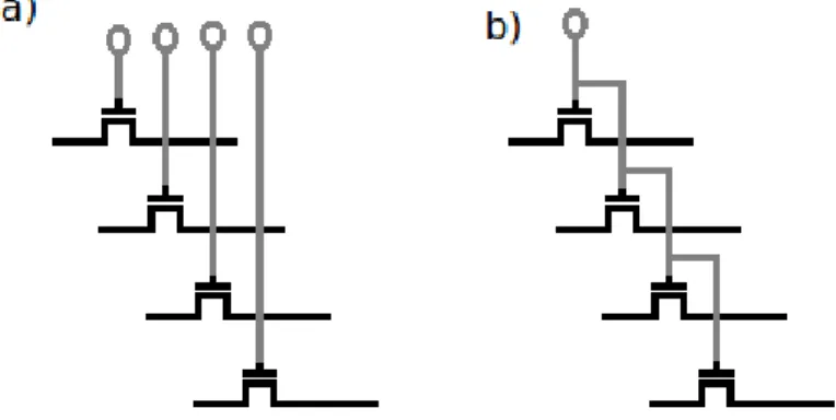
Fine-grained functional units perform a single function in a small number of bits. The most abundant example of fine grained functional units are look up tables. By shifting a combina-tion of bits, these units can output any kind of result. This flexibility gives them the power of implement any digital circuit. However, fine grained functional units use significant areas, have significant delays, and have high power consumptions when compared with the coarse grained alternatives. Although less flexible, coarse-grained functional units can eliminate these problems, like the DSP48E (fig.2.1) blocks present in the Xilinx Virtex family FPGAs. These functional units although not as flexible, can perform faster and using less area.
The topology of the reconfigurable interconnects has also some impacts in the efficiency of the FPGA’s reconfigurable fabric. In the fine-grained topology (fig.2.2a), every wire of a bus can be switched independently while in the coarse-grained alternative all the bus’ wires have to be mutually switched on or off (fig.2.2b). Usually, the reconfigurable interconnects and the functional units go hand-in-hand, i.e., coarse grained units are, normally, connected using coarse grained interconnects. While the fine grained approach provides flexibility, it also has the downside of reconfiguration overhead, since every wire of a bus has to be configured.
Some disadvantages are observed when comparing an FPGA with an ASIC. In the design of an FPGA, the basic logic blocks (AND gates, OR gates, NOT gates, etc.), the harder blocks (multipliers,etc.), as well as all the other components, are already placed in the IC. When the
Figure 2.1: DSP48E slice.
designer defines the connections of two components, the routing may not be the best solution. For instance, if an output of a Multiplier is to be connected to an AND logic gate that is very far, because of architecture constraints, a large routing wire (along with all the switching transistors) will be used, causing propagation delays, reducing the overall performance of the circuit. This also gives place to a greater silicon area and power consumptions.
Besides these two, more commonly used hardware alternatives, there are cases where pre-made graphics processing units were used to hardware accelerate applications. For instance, in [7] a GPU was used as a coprocessor to accelerate a Finite-Difference Time-Domain method. Another example is the FFT acceleration processes using a GPU [8].
Through OpenGL and Direct X applications, modern GPUs can become programmable hard-ware devices, being possible to implement various applications. GPUs can provide the required processing speed because of their high parallel application purpose and floating point data type capabilities. However, when using GPUs, the application has to be modelled to the architecture,
Figure 2.2: Different interconnect configurations. Fine-grained on the left and coarse-grained on the right.
2.1 Hardware Acceleration 9 A B C D Instruction 1 A B … Instruction 2 A B C D Instruction 1 A B C D Instruction 2 A B C … Instruction 3 A B … Instruction 4
Figure 2.3: Execution of an instruction without pipelining.
instead of generating a specialized architecture.
2.1.2 Hardware Techniques
Some techniques are used when proceeding to hardware acceleration. For Example, by con-verting the floating-point data representation to fixed-point, the number of functional units are reduced hence reducing the size used in the FPGA. Since the amount of parallelism that can be used in an FPGA is directly proportional to its available logic elements, using fixed-point data types will result in more units available to use in parallelization.
Another technique is the use of look up tables for expensive operations (trigonometric func-tions, as an example). By storing the already computed values in memory, it is avoided the use of larger computational blocks that would use a large number of elements. This technique also saves FPGA space and can be used to provide hardware acceleration in the same way as the previous technique.
The pipelining technique is widely used for hardware acceleration. This technique consists in dividing the instruction’s execution in individual tasks so that each one can be processed by different functional units. As an example, consider the figure2.3. There, an instruction composed by 4 tasks is being executed in line and, upon execution, the processor will start to execute the next instruction. By pipelining this instruction, every task is executed by a different functional unit, as shown in fig2.4. In the ideal case, pipelining enables one instruction to be done at every cycle. This however does not mean that the instruction will execute faster.
Since every sub-task is performed independently, more than one task can be performed at the same time. Taking as an example the operation D = (a + b) × (a − c), it could be divided in two stages: in the first, the addition and subtraction could be proceeded in parallel; the second stage is composed by the multiplication. If the operation was to be made multiple times, the multiplication
A
B
C
D
Instruction 1A
B
…
Instruction 2A
B
C
D
Instruction 1A
B
C
D
Instruction 2A
B
C
…
Instruction 3A
B
…
Instruction 4of the instruction n could be made at the same time as the addition and subtraction of the instruction n+1.
2.1.3 Architecture Alternatives
There is a significant interest in hardware/software co-design aiming to accelerate a software application where the most time critical parts are implemented in hardware blocks of the FPGA while the parts that cannot be efficiently accelerated are handled by the embedded processor. Nor-mally, complex control sequences such as variable length loop are better implemented in software, while fixed datapath operations obtain better acceleration when mapped to hardware. This can pro-vide high degrees of acceleration. By using an hardware/software hybrid “significant performance improvements, approaching super-computer speeds, can be achieved in a number of application areas, including cryptography, data compression and string matching” [9].
Most of the time, in the software/hardware hybrid, the reconfigurable fabric works as copro-cessor to a microprocopro-cessor host (this can also be made with a custom circuit). In the reconfigurable logic the most computational intensive parts are handled while, variable length loops and branch control operations that cannot be efficiently mapped to the FPGA are handled by the micropro-cessor. An inherent advantage of using the reconfigurable fabric as a coprocessor is the speed-up resultant of the parallel computing. This speed up can be characterized by Amdahl’s law. The modern version of Amdahl’s law states that if a fraction f of a computation is enhanced by a speed-up S, the overall system speed-up is:
Speed− upenhanced( f , S) =
1
(1 − f ) +Sf (2.1) This of course, when both the processor and the reconfigurable mesh are executing in parallel. Also, it should be noted the the maximum speed-up achievable depends on the time needed for the sequential fraction of the program. As an example consider an algorithm that takes five minutes to execute and of those five minutes, one cannot be parallelized. Regardless of the parallelization degree, the overall algorithm cannot be executed in less than one minute.
Many computational structures, making use of a standard microprocessors and one or more reconfigurable meshes have been proposed. Some with higher communication speeds between the processor and the mesh, others with higher degree of computing independence. This structures are presented in figure2.5and explained with more detail in [1].
In the first case (fig.2.5a) the reconfigurable unit is used within the microprocessor as func-tional units connected to its main datapath. These funcfunc-tional units can provide the processor the ability of being programmed with custom instructions that can be altered in the future. These func-tional units require constant supervision of the processor and, therefore, is the alternative with the greatest communication overhead. An example of this kind of architecture is the one present in the Chimaera reconfigurable functional unit, a system design to overcome communication bottleneck
2.1 Hardware Acceleration 11
Figure 2.5: Various Processor-FPGA architectures (adapted from[1]).
by integrating reconfigurable logic into the host processor itself [10]. The interconnect structure of Chimaera lends itself well to automatic compilation.
The second case(fig.2.5b), uses the reconfigurable fabric as a coprocessor to which the micro-processor sends data (and controls). The comicro-processor executes independently of the micro-processor, i.e., doesn’t require constant supervision from it, and after completion returns the results. These kinds of architectures are designed to exploit large amounts of fine-grained parallelism in applications. An architecture similar to this was presented by [11] where both, an FPGA and a reconfigurable multimedia array coprocessor solutions were used to achieve speedups ranging from 2.3 to 7.3 times.
The alternative present in fig.2.5c, uses a reconfigurable mesh as a processor in a multipro-cessor system. This implementation provides greater computing independence but at the cost of communication speed.
In the alternative 2.5d the communication speed is even lower but the reconfigurable mesh executes almost as a stand alone computing system.
Other alternatives can be followed. In the COSYMA[12] system, it is attempted to have most of the operations executed by software while hardware is only synthesized for the operations that violate timing constraints. On the other hand, the PAM system, is a reconfigurable hardware coprocessor (making use of an FPGA) tightly coupled to a host workstation [13]. The PRISM[14] approach compiles a program to produce an hardware image used to characterize a reconfigurable platform, and a software image which is similar, in function, to the executable image produced by a conventional compiler consisting of machine code ready to execute in a microprocessor along with code that integrates the synthesized hardware.
2.2
High-Level Synthesis
Using a HDL to develop an hardware design capable of performing complex functionalities is, sometimes, a cumbersome and error-prone task. In fact, the creation of hardware modules from both VHDL and Verilog requires the developer to have in mind the characteristics of the target FPGA, timing constraints, communication delays, etc. For larger projects it is needed a set of tools with a certain degree of abstraction where, only a description of the final implementation’s desired behaviour is described.
Because C is one of the most widely used programming languages with high degree of ab-straction, and because most of the software to be hardware accelerated is written in C, more and more hardware designers and software programmers are looking at ways to configure hardware by making use of this programming language.
But standard C is not a good choice for designing hardware, given that although it ensures algorithm causality, timing constrains like execution time of a given function or when its input values should be ready to be used are not specified. Since a software algorithm executes in a sequential fashion, failing to meet temporal requisites does not have serious complications (being the only exception in Real-Time systems) and only the execution time of the overall application is affected. However, the same is not true for an hardware module where failing to respect temporal constraints has catastrophic implications such as, errors in the handled data or even shutting the hardware normal functioning.
"Successful hardware synthesis from C seems to involve languages that vaguely resemble C, mostly its syntax"[15]. Some of those C-like hardware languages are:
• Cones — Synthesizes a single function to combinational blocks. Supports loops (unrolling them), conditionals and arrays;
• HardwareC — Behavioural hardware syntax with C-like syntax ;
• SystemC — Set of C++ classes and macros that supports hardware and system modelling; • Handel-C — C variant where every assignment takes exactly one clock cycle;
• SpecC — Extension to C with constructor for concurrency, pipelining, etc.;
The main disadvantage of this C-like tools is that their low resemblance to C implies that the programmer has to, effectively, learn a new language. Also, providing software programmers with these tools is not enough to make them good hardware designers since they are used to implement algorithms that run in a sequential manner and, therefore, their ability of designing concurrent tasks may not be well developed. According to [15], software follows a sequential, memory-based execution model derived from Turing machines1, whereas hardware is fundamentally concurrent. The reason for this comes from the difficult task of designing parallel algorithms, as well as, a dis-agreement in which are the most efficient ways to provide parallelism to the software’s algorithms.
2.2 High-Level Synthesis 13
Having these tools a different syntax from standard C, they’re also unsuitable when it comes to accelerate functions of a pre-existing C application (or all the application) since, the code would have to be rewritten.
It is the role of the HLS (High Level Synthesis) tools to transform algorithmic level behavioural specification into an HDL capable of synthesize hardware modules that execute the same func-tionalities as the application (or as the application’s function) to be accelerated. This tools also improve the time-to-market since the debug, verification and validation processes of the design are simplified when done at an high abstraction level. By guiding the automated synthesis flow to generate the architecture that meets the desired goals, instead of manually transform the software language to an HDL, it is obtained a gain in development and debugging time.
Some of these tools, generate only the hardware configuration of the system, i.e, when an HLL (High Level Language) is processed by these tools, only the equivalent hardware is inferred. In a software/hardware co-design, the designers will have to adapt the applications software to account for the new generated hardware. There are however tools that enable the designer to specify which parts will be mapped to hardware and which will continue to be executed as software, either by the definition of pragmas or automatically by determining the acceleration gained through the execution of a code fragment in hardware.
According to [16] an HLS tool shall execute the following steps: Compilation, allocation, scheduling, binding and RTL (Register Transfer Level) generation.
In the compilation phase, a series of optimizations such as, loop transformation and dead-code elimination, are made over the algorithm to be synthesized. Also, it is created a formal representation where the control and data flow are defined.
In the second phase, i.e, the allocation phase, the type and number of hardware resources needed to satisfy the design constraints are defined. This components are selected from an RTL library where their power consumption, area and delay must be present.
The scheduling phase is responsible to define when the variables needed by a functional unit shall be present in its inputs. Also in this phase it is specified when the operation should begin its execution.
When there are multiple functional units capable of executing a function, the ones that opti-mize the final hardware module shall be chosen in the binding phase.
Having all the decisions been made in the previous phases, they can be used to generate an RTL model that respects the design.
One example of these HLS tools is Mentor Graphics’s Catapult C. This tool analyses pure and untimed C++ to generate an RTL netlist in Verilog, VHDL and SystemC. There are some reports[17][18] of applications using Catapult to transform C into RTL.
2.3
Tools
A brief description of the tools that were used throughout the thesis’ project, will be described in this section.
2.3.1 Virtex-5
To hardware accelerate the application at hand, it was used a Virtex-5 FPGA; more precisely a XC5VFX70T with an embedded PowerPC 440 hard-core processor. The Virtex-5 is an evolu-tion of other FPGAs of the Virtex family, using 65-nm copper process technology and provide a programmable alternative to custom ASIC technology. Some of its common features are [19]:
• 6-LUT + Express Fabric;
• 36Kb Dual-Port Block RAM / FIFO with ECC; • SelectIO with IDELAY/ODELAY and SerDes; • 10/100/1000 Mbps Ethernet MAC;
• PCI-Express Endpoint Blocks; • GTP 3.75 Gbps Transceivers; • GTX 6.5 Gbps Transceivers;
• PowerPC440 Processors (one in the case of the XC5VFX70T); • 550 MHz Clock Management;
• 25x18 DSP Slices;
• Integrated System Monitor A/D Converter; • Advanced Configuration Options.
The Virtex-5 family has also some additional capabilities to extend the functionalities of the PowerPC processor, like crossbar connections or auxiliary processing-unit controllers which can be used to connect the processor to a 128-bit Floating Point Unit which is a soft co-processing unit. This hardware coprocessor is used to address the lack of a floating point unit in the Pow-erPC processor. Because it is external to the processor, arithmetic operations using floating point datatypes will take longer to execute.
The XC5VFX70T belongs to the FXT sub-family characterized as being high-performance embedded systems with advanced serial connectivity. The main reason for choosing an FPGA of this sub-family instead of any other sub-family (LX for high-performance general logic ap-plications, LXT for high-performance logic with advanced serial connectivity, SXT for High-performance signal processing applications with advanced serial connectivity or TXT for high-performance systems with double density advanced serial connectivity) was justified by the fact
2.3 Tools 15
that the FXT sub-family is the only one that contains one (or two) PowerPC 440 RISC Core[20], indispensable to execute the software application.
Perhaps the most important feature of this FPGA are its 128 DSP48E slices that operate at 550MHz[20]. With this, multiple slower operations can be implemented, using time-multiplexing methods. These slices provide improved flexibility and utilization, supporting 40 dynamically con-trolled operating modes, including multiply, multiply accumulate (MACC), multiply add, three-input add, barrel shift, wide-bus multiplexing, magnitude comparator, bit-wise logic functions, pattern detect, and wide counter.
To be able to work with this FPGA in a easier way, the ML507 (fig 2.6) development board was used. This development board, provides a wide set of features, which saves much of the development time if one would have to manually configure the controlling components. Some of those are [21]:
• XC5VFX70T-1FFG1136 — Virtex-5 FPGA;
• Two Xilinx XCF32P Platform Flash PROMs — for storing large device configurations (32 Mb each);
• Xilinx System ACE CompactFlash configuration controller — used to load the FPGA’s configuration, as well as, the embedded Linux operating system.
• 64-bit wide, 256-MB DDR2 small outline DIMM
• 10/100/1000 tri-speed Ethernet PHY transceiver and RJ-45 with support for MII, GMII, RGMII, and SGMII Ethernet PHY interfaces — Used in the project to send commands and transfer executable files via Ethernet.
2.3.2 PowerPC 440
The PowerPC 440 (PPC440) is a processor of the IBM’s PowerPC 400 family. These are 32-bits embedded RISC processors that are built using the Power Architecture technology. These processors are designed to fit inside dedicated circuits like ASICs, microcontrollers and FPGAs.
Having first appeared in 1999, the PPC440 core is a high-performance, low-power consump-tion engine that implements the flexible and powerful Book-E Enhanced PowerPC Architecture. Embedded in the XC5VFX70T FPGA, is capable of up to 550 MHz operation, 1000 DMIPS and Out-of-order execution[20].
Some of the main features of this processor are[22]:
• High performance, dual-issue, superscalar232-bit RISC CPU;
• Separate 32 kB instruction and data L1 caches;
Figure 2.6: ML507 development board.
• Instruction cache parity; • Data cache parity;
• D-cache full-line flush capability; • Memory management unit; • UTLB parity;
• Multiple core Interfaces defined by the IBM CoreConnect on-chip system architecture.
This processor has also a PLB(Processor Logic Bus) interface of 128 bits and is fully compati-ble with the IBM CoreConnect on-chip system architecture, providing the framework to efficiently support system-on-a-chip (SOC) designs[23]. The PLB interface serves as a mean of communica-tion with all the peripherals external to it. In the case of this thesis, the PLB will be mostly used for communicating with the hardware modules of the FPGA.
To simplify on-chip devices attachments, the core contains various interfaces[22], namely: • Processor local bus (PLB);
• Device configuration register (DCR) interface; • Auxiliary processor unit (APU) port;
2.3 Tools 17
• JTAG, debug, and trace ports;
• Interrupt interface;
• Clock and power management interface.
The PPC440 includes a seven-stage pipelined PowerPC processor, which consists of a three-stage, dual-issue instruction fetch and decode unit with attached branch unit, together with three independent, four-stage pipelines for complex integer, simple integer, and load/store operations, respectively. It also includes a memory management unit (MMU), separate instruction and data cache units, JTAG, debug, trace logic, and timer facilities.
This processor is available in the ML507 development board used in this thesis. It’s aim will be to execute the software part of the application. Also, through the PLB, it will send the data to the FPGA’s RAMs, as well as the, the handshake signal to control the hardware modules.
2.3.3 Catapult C
Catapult C Synthesis is an algorithmic synthesis tool that outputs RTL (Register-Transfer-Level), netlists (VHDL, Verilog, and SystemC), simulation scripts, schematics and reports from C++ working specifications. This was the tool that was used throughout this thesis to convert some of the functions of the application that were initially in C to Synthesizable hardware. The strongest feature of this tool is it’s ability to accept untimed C++ algorithms to be synthesized to RTL. Typically, the C++ code from a system designer can be used to generate correct results that meet latency and timing constraints, having however, to be made some code changes to meet area and power goals. Besides the C++ to hardware compilation, Catapult C also provides:
• C++ compiler and file editing — This compiler has more complete checking than a stan-dard C++ compiler;
• Algorithm and architecture analysis — To analyse various algorithm parameters such loop size, variable size, etc.;
• Micro-architecture constraints — Loop unrolling, pipeline, memory access,etc.;
• Optimization and RTL hardware generation — For better area and/or latency solutions;
• SystemC Verification Flow — Automates the generation of a SystemC testbench;
• Integrated tool flows— For power analysis, formal verification and source code linting.
The synthesis process flow to create an hardware module using Catapult C can be seen in figure2.7. The two leftmost blocks are the action that are not performed in Catapult C.
Characterize Libraries and Create Custom IP
Prepare C Code for Synthesis Select Technology Constraints, Clocks, Library and IP Set Architectural Constraints Analyze scheduling Generate RTL and Reports SystemC Verification Flow Synthesize, Place and Route Timing Goals Met? Design Goals Met? Catapult Y Y N N
Figure 2.7: Catapult C process flow.
In addition, the integrated SystemC verification flow automates the generation of a SystemC testbench which allows to verify that the C++ design matches the resulting hardware. All these automated processes can increase productivity significantly over standard RTL writing.
Catapult C works in a Solution basis, meaning that changes made to the source code, architec-ture constraints etc., will be branched to different solutions so that all the alternative implementa-tions are available for comparison.
2.3.4 Other Tools
• Gprof
The hardware acceleration process is best achieved if the most time consuming and computa-tionally critical functions are identified. To that end, the profiling tool Gprof was used.
Gprof analyses the execution time of each and every function of a software application. This analysis is proceeded in the actual execution of the program, using a sampling process. Afterwards, two tables can be viewed where both the total and relative time spent by a function (both by itself and all it’s children), the number of time it was called and functions’ hierarchy is shown.
• Precision RTL
Precision RTL is a comprehensive toolsuite, providing design capture in the form of VHDL, Verilog and SystemVerilog entry, advanced register-transfer-level logic synthesis, constraint-based optimization, timing analysis, schematic viewing, and encapsulated place-and-route. This tool was mainly used because the Verilog files that were generated by Catapult C, were in too high level to be recognizable by XILINX ISE, i.e., it contained statements not recognized by XILINX ISE.
2.3 Tools 19
Precision RTL was needed to synthesize the gate level specification to be effectively used by the ISE.
• Xilinx ISE
Development environment for synthesis and analysis of HDL designs. ISE (Integrated Syn-thesis Environment) also enables to perform timing analysis and simulation of the synthesized hardware when faced to external stimulus.
The Verilog files created by Precision RTL were passed to ISE where they were integrated in a more complex core (in Verilog also) to create a netlist file that would describe the FPGA logic blocks and connections.
• Modelsim
ModelSim is an advanced simulation and debugging tool. Either Verilog, VHDL or system C languages are accepted to be simulated.
This tool was used to check if all the hardware modules to be synthesized, were performing the required functionalities. By creating a testbench file containing input stimulus, they could be then applied to the modules (in simulation) to analyse both their internal and external logic values.
• Xilinx XPS
The XPS (Xilinx Platform Studio) enables an easier integration of the designed hardware blocks with the embedded PowerPC processor and all the other constituents of the FPGA(serial ports, Ethernet ports etc.).
Chapter 3
Analysis of the Stereo Navigation
Application
In this chapter, the Stereo Navigation application will be analysed to determine which parts of the source code can be replaced by dedicated hardware blocks to obtain an acceleration in its execution time. A description of the application will be made, followed by the steps made in order to port the application’s algorithm to the targeted development board. The chapter is finalized with an analysis of the application’s most critical parts.
3.1
Application Overview
The application to be accelerated, the Stereo Navigation application will analyse a stream of images, in pairs, coming from two cameras. The algorithm analyses one image from each camera taken at the same time by:
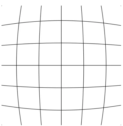
• Rectifying the image — To remove distortion in each image caused by the lenses of the camera. One such example is the barrel distortion caused by the lenses curvature, present in figure3.1(taken from [24]);
• Extracting features — To find significant elements in the images and describe them using an hash-like information vector. Here, the Harris corner detector is used;
• Matching features — Compares the features extracted in a pair of images at a given mo-ment with the features of another pair of images analysed in the preceding momo-ment. This step is used to increase the probability of a correct 3D reprojection;
• Making a 3D reprojection — Derive 3D coordinates of a point from its image projections;
Figure 3.1: Example of image distortion caused by the camera lenses. In this case the Barrel distortion.
• Robust pose estimation — To reliably remove members that were matched incorrectly and to produce the estimate of the transformation between the two sensor reference frames, allowing to detect motion.
By analysing pairs of pictures and comparing, in consecutive pairs, how the features of the pictures have changed, the system can also calculate translation, rotation, speed, and position of the vehicle.
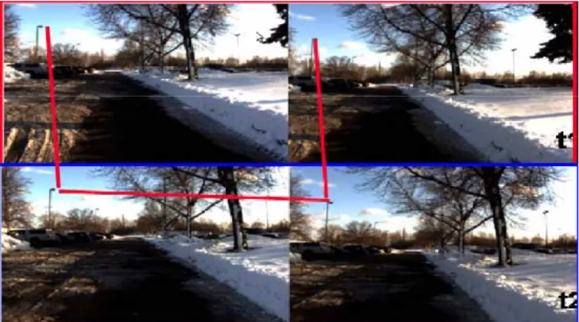
In figure3.2, the two top images are taken at the same time t1 by the left and right cameras. The bottom images are taken also by the same two cameras in the next frame t2 to determine the vehicle position and movement. However in theory it could be possible to infer the position of a feature in a three-dimensional space using only a pair of images, the probability of having a correct match in a cluttered urban environment is often around 20% as stated by [24]. To raise the correct match probability, it is used a circular check where, the features detected by the two cameras are compared with themselves and with the ones of the previous capture instant (the two left images are matched with each other, being done the same to the two right images). This circular check is presented in figure3.2. With this, the probability of a correct assignment is increased.
The version that was used in this thesis was, however, a little different in the way that the system did not have the two cameras installed. To simulate the camera input, two options were
3.2 Porting the Application 23
Figure 3.2: Detection of an obstacle, as well as, speed, translation and rotation of the vehicle by the application.
possible: either the images in grayscale were stored in a file where the application would access them or, a representation of the images was already present in the source code as data. The second option was chosen. In this option, the image is represented by a matrix whose elements’s values represent a pixel representation in 8-bit grayscale format, being that the value 0 represents white, the 255 black and all the values in the middle represent shades of gray.
3.2
Porting the Application
In a first approach, there was the need to execute the original Stereo Navigation application in the embedded processor of the ML507 board. This first step was of the utmost importance, in the matter that it gave crucial data that was useful to, in the later stages, infer the degree of acceleration obtained. The most critical information considered was:
• Execution time of each function — To determine which are the functions that take the most time to execute and, therefore, are slowing down the overall application.
• Execution time of the overall algorithm — In order to be able to tell the amount of accel-eration that was achieved.
• Output of the application — To ensure that the solution found with the hardware acceler-ation is working correctly.
To make it easy to integrate the application’s source code into the embedded processor, it was chosen to install a Linux kernel in the development board. The reason for that, is because the interface between the software, the CPU, the memory and other devices is not specified by the program.
There was the possibility of executing the application in a standalone fashion. Using XPS, it was possible to import the application to run in the PowerPC processor however, some changes
Application
Kernel
CPU
Devices
Memory
Figure 3.3: Kernel making the bridge between hardware and software.
to the code had to be made which could affect the final execution time of the application. The biggest disadvantage of using this alternative was, that the profiling tool gprof could not be used to determine the execution time of each function.
The use of an operating system eases the software development by providing a series of con-venient services like access to a (RAM-based) disk file system, remote network access, virtual memory management and also simplified procedures for profiling the application to estimate the execution time of each function. These advantages far exceed the disadvantage of the overhead caused by the operating system in the processor.
3.2.1 Installing the Kernel
As said before the Kernel makes the bridge in a machine between the software running on it and its hardware. For that reason, and since the architecture of the processor and the other devices present in the development board are not the same as the ones present in a standard computer, a version of the Linux Kernel aiming the PowerPC 440 processor had to be installed. This kernel was obtained from [25] and the instructions present there were followed.
The first step was to configure the reference design in XPS. The reference design is a set of files recognized by XPS that represents all the components present in a given development board (processor, LEDs, serial port, USB port, user defined hardware modules, etc.) and how they are interconnected in the FPGA to the processor by being assigned to each an address code. Every time a given core is needed to execute a specified action, the required data is sent to its address via the PLB (Processor Local Bus). An example of how the cores are connected to the processor in the reference design is shown in figure3.4.
3.2 Porting the Application 25
Figure 3.4: Example of the addresses given by XPS to each of the cores.
A device tree was added to the design which, according to [26], is scanned during the boot phase by the Linux Kernel to build an internal representation that will be used at run time to give the information about the device. In other words, this will describe the hardware to the Kernel by giving names to the components (like ttyS0 for serial port 0 or eth1 for the Ethernet port 1, for instance), describing their functions, etc. The changes made were then processed by XPS to generate a bitstream file. This file has the informations of the layout of all the IP Cores and is used to configure the FPGA at the startup.
When the Kernel was, finally, operational in the development board, it could be accessed via telnet1; by inputting commands in the development host’s console they were sent to the ML507 board. With this, the development board could be used to execute the application, but first it would have to be compiled to a type of executable that the development PowerPC processor could recognize.
For a more detailed explanation of how the Kernel was compiled to the target board, refer to the appendixA.5.
3.2.2 Cross-Compiling the Application
The C-language files are, in fact, just text files which describe in a structured and well defined manner the behaviour of the desired executable file. This files are intended for readability by the user/programmer and not to be executed by the processor. It is the task of the compiler to interpret the source code and translate it to machine code, producing a file that can be executed.
When writing a code, there are some functions that are widely used by the programmers. To make the writing of the code easier, some functions are already present in the C standard library. So, if a programmer wants to make an application that, for instance, calculates the tenth power of
the number two, instead of having to make himself a function that multiplies the number two, ten times, the function pow() could be used. This facilitates the work and, also, eliminates the chances of more complex functions to have errors or bugs.
Different platforms run different types of executable files. A C-language program compiled to run in a platform may not work in a different one. The reasons for this are the different endianness, word size, word alignment, etc. that each architecture has. Normally a computing device has a compiler in order to build an executable file that respects its architecture constraints.
Because of the limited resources that the used embedded device has, having a compiler in-stalled in it would consume too much memory space and, for that reason, most embedded devices do not contain any compiler. To work around this problem, a cross-compiler is used which com-piles the C-code in the cross-development host aiming for the target device. In this case, a general purpose computer running a Linux distribution was used as a cross-development host to compile the source code in order to build executable files that could, effectively, run in the development board’s processor. To create an executable file, capable of running on an embedded system, the editor of the cross-development host is used to create/alter the source code, the debugger is used to check for errors, and the cross-compiler to create the executable file. After that, the executable file is ported to the embedded system where it will be run.
The standard library of functions is not present in the development board, due to its limited resources also. Instead, the libraries used are the ones present in the cross development host. To include the standard library’s files in the final executable, the -static flag must be set when compil-ing. This command instructs the compiler to copy all the functions used by the application directly to the executable from the standard library during the linking phase. This makes an executable file bigger in size but relieves the embedded system to have all the libraries present. On the other hand, in the dynamic linking alternative, the executable file references only the library from which to get the used function so, they would have to be present somewhere in the development board, using memory space.
The cross-compiler used was the powerpc-linux-gcc contained in the ELDK 4.2 (Embedded Linux Development Kit) package. According to [27], the provided package includes the GNU cross development tools, such as the compilers, binutils, gdb, etc., and a number of pre-built target tools and libraries necessary to provide some functionality on the target system. To cross-compile the application using the powerpc-linux-gcc cross compiler the following command had to be im-puted in the console:
3.3 Profiling the Application 27 ConvRepl1 ConvRepl1 start done Software Hardware
Figure 3.5: Hardware accelerating the application (on the right) vs software-only implementation (on the left).
With this, the executable file was set to run in the PowerPC 440 processor. Other compilation options could be set in the same way that is done for the regular gcc compiler.
3.3
Profiling the Application
Because the application was running in one processor, when a function of the program that was more time consuming was executing, it would delay the quicker functions. While in execution, the slower function would make the others to be stopped waiting until they were called. This causes a bottleneck. By speeding up the most time consuming functions of the code, the bottleneck is "enlarged" and the application shall be accelerated respecting a balanced trade-off between speed and FPGA area.
Only the most critical parts of the algorithm, or in other words, the most time consuming functions, are desired to be hardware accelerated. The main reason for this is the limited reconfig-urable mesh area available to create each hardware module which, would not be enough to create hardware modules to replace all the application’s functions. Giving priority in the conversion of the most critical functions to hardware modules, provides the highest degree of acceleration.
In order to determine the most critical functions, powerpc-linux-gprof was used to profile the code compiled with four degrees of optimization: no optimization, -O1, -O2 and -O3. The powerpc-linux-gprof is identical to gprof, the only difference being that it is aimed to profile ex-ecutable files cross-compiled to the specific development board’s processor. For comparison with the outputted values of the application and the speed obtained, the application was also compiled in a computer with a i5 quad-core processor running at 3.20GHz.
The following results (from subsection3.3.1through3.3.5) were taken from the flat profile2 tables obtained in Gprof (and powerpc-linux-gprof).
% time cumulative secs self secs calls self ms/-call name 28.20 76,59 76,59 1440 53,19 ConvVBRepl2_uS_hS_yS 28.13 152,98 76,39 1440 53,05 ConvVBRepl1_uS_hS_yS 13,49 189,62 36,64 960 38,17 ConvVBConst_uS_hS_yS 7,48 209,94 20,32 10 2032,22 R_c4_RobustPoseEstimate_library 7,06 229,12 19,18 2700 7,1 sift_match_one 6,52 246,84 17,72 480 36,92 harrisTile_model_step Table 3.1: Profiling with no optimization in the PowerPC processor (ten executions).
3.3.1 Profiling With No Optimization
The first approach was to profile the code with no optimizations. By doing this, the com-piler’s goal is to reduce the cost of compilation and to make debugging easier. However, since no optimizations are made, the created executable file will take longer to execute.
With this in mind, the profiling of the executable file was made. Because the runtime figures that gprof gives are based on a sampling process, they are subject to statistical inaccuracy. The solution advised by [28] is to combine data from several runs. For better accuracy, the results that will be presented throughout this document are based on ten executions of the profiled application. The result of the “No optimization” flag can be seen in the table 3.1.
The information contained in each column of the table 3.1represents:
• % time — Percentage of the time that is spent in the function present in the column "name". This values do not account for the time the function is stopped waiting for others to execute.
• Cumulative secs — The time spent in the function plus the time spent in all the functions above.
• Self secs — The amount of time spent on the function throughout the execution of the application. It’s only accounted its execution time.
• Calls — Number of times the function was called in the application.
• Self ms/call — Average time spent on the function per call.
• Name — Name of the function.
It can be seen that there are three functions that consume much more time than the oth-ers namely, ConvVBRepl2_uS_hS_yS, ConvVBRepl1_uS_hS_yS and ConvVBconst_uS_hS_yS. With the use of powerpc-linux-gprof it could be determined that the total execution time for the application took 27,16 seconds (or 271,57 seconds for ten executions).
![Figure 2.5: Various Processor-FPGA architectures (adapted from[1]).](https://thumb-eu.123doks.com/thumbv2/123dok_br/18868375.931008/29.892.262.698.157.425/figure-various-processor-fpga-architectures-adapted-from.webp)