Repositório ISCTE-IUL
Deposited in Repositório ISCTE-IUL:
2019-01-10Deposited version:
Post-printPeer-review status of attached file:
Peer-reviewedCitation for published item:
Monteiro, R. J. S., Rodrigues, N. M. M., Faria, S. M. M. & Nunes, P. J. L. (2018). Light field image coding: objective performance assessment of Lenslet and 4D LF data representations. In Andrew G. Tescher (Ed.), SPIE Optical Engineering + Applications. San Diego: SPIE.
Further information on publisher's website:
10.1117/12.2322713Publisher's copyright statement:
This is the peer reviewed version of the following article: Monteiro, R. J. S., Rodrigues, N. M. M., Faria, S. M. M. & Nunes, P. J. L. (2018). Light field image coding: objective performance assessment of Lenslet and 4D LF data representations. In Andrew G. Tescher (Ed.), SPIE Optical Engineering + Applications. San Diego: SPIE., which has been published in final form at
https://dx.doi.org/10.1117/12.2322713. This article may be used for non-commercial purposes in accordance with the Publisher's Terms and Conditions for self-archiving.
Use policy
Creative Commons CC BY 4.0
The full-text may be used and/or reproduced, and given to third parties in any format or medium, without prior permission or charge, for personal research or study, educational, or not-for-profit purposes provided that:
• a full bibliographic reference is made to the original source • a link is made to the metadata record in the Repository • the full-text is not changed in any way
The full-text must not be sold in any format or medium without the formal permission of the copyright holders.
Serviços de Informação e Documentação, Instituto Universitário de Lisboa (ISCTE-IUL) Av. das Forças Armadas, Edifício II, 1649-026 Lisboa Portugal
Phone: +(351) 217 903 024 | e-mail: [email protected] https://repositorio.iscte-iul.pt
Light field image coding: objective performance assessment of
Lenslet and 4D LF data representations
Ricardo J. S. Monteiro*
a,b, Nuno M. M. Rodrigues
a,c, Sérgio M. M. Faria
a,c, Paulo J. L. Nunes
a,ba
Instituto de Telecomunicações, Portugal,
b
Instituto Universitário de Lisboa (ISCTE-IUL), Lisbon, Portugal,
cESTG, Instituto Politécnico de Leiria, Portugal
ABSTRACT
State-of-the-art light field (LF) image coding solutions, usually, rely in one of two LF data representation formats: Lenslet or 4D LF. While the Lenslet data representation is a more compact version of the LF, it requires additional camera metadata and processing steps prior to image rendering. On the contrary, 4D LF data, consisting of a stack of sub-aperture images, provides a more redundant representation requiring, however, minimal side information, thus facilitating image rendering. Recently, JPEG Pleno guidelines on objective evaluation of LF image coding defined a processing chain that allows to compare different 4D LF data codecs, aiming to facilitate codec assessment and benchmark. Thus, any codec that does not rely on the 4D LF representation needs to undergo additional processing steps to generate an output comparable to a reference 4D LF image. These additional processing steps may have impact on the quality of the reconstructed LF image, especially if color subsampling format and bit depth conversions have been performed. Consequently, the influence of these conversions needs to be carefully assessed as it may have a significant impact on a comparison between different LF codecs.
Very few in-depth comparisons on the effects of using existing LF representation have been reported. Therefore, using the guidelines from JPEG Pleno, this paper presents an exhaustive comparative analysis of these two LF data representation formats in terms of LF image coding efficiency, considering different color subsampling formats and bit depths. These comparisons are performed by testing different processing chains to encode and decode the LF images. Experimental results have shown that, in terms of coding efficiency for different color subsampling formats, the Lenslet LF data representation is more efficient when using YUV 4:4:4 with 10 bit/sample, while the 4D LF data representation is more efficient when using YUV 4:2:0 with 8 bit/sample. The “best” LF data representation, in terms of coding efficiency, depends on several factors which are extensively analyzed in this paper, such as the objective metric that is used for comparison (e.g., average PSNR-Y or average PNSR-YUV), the type of LF content, as well as the color format.
The maximum objective quality is also determined, by evaluating the influence of each block from each processing chain in the objective quality of the reconstructed LF image. Experimental results show that, when the 4D LF data representation is not used the maximum achieved objective quality is lower than 50 dB, in terms of average PSNR-YUV.
Keywords: Light Field, Light Field Image Coding, Light Field Data Representation, JPEG Pleno, Objective Performance Assessment
1. INTRODUCTION
Light field (LF) imaging technology allows the acquisition of not only radiance data from the light rays hitting the camera’s sensor, but also their angular information. This is possible by using a microlens array (MLA) located between the camera’s main lens and the camera sensor [1], each microlens creates a micro-image (MI) on the sensor. Thus generating 3D information, which enables a set of relevant features, like changing the focus and the perspective after the picture has been taken [1].
When capturing a LF image, the sensor capacity is being used to capture both spatial and angular information. Because of this, the rendered images tend to present only a fraction of the total available spatial resolution of the camera sensor [2]. Therefore, LF cameras tend to use larger sensors, i.e., more than 40 Megapixels [3], increasing the total amount of information to be stored or transmitted, when compared with traditional cameras. Since state of the art image coding solutions were not designed for LF images, when applying these techniques to LF image coding, i.e., without the use of proper LF compression techniques, the coding efficiency can be very low.
To render a 2D image from LF data, metadata provided from the acquisition camera is necessary. Since there is no current standard which specifies the metadata required for rendering purposes, several authors have proposed different solutions that require different amounts of metadata do be stored or transmitted. There are two main LF image formats that will be referred to as Lenslet and 4D LF [4]. The Lenslet data representation requires minimum pre-processing before the encoding step, however, in order to properly render the images from the decoded LF image, camera metadata is required [4], [5]. The 4D LF data representation consists on a stack of sub-aperture images (SAIs), which are generated from the Lenslet LF image [5], prior to the encoding step. The 4D LF data representation requires more pre-processing than the Lenslet data representation, but this format facilitates the rendering at the decoder side since minimal camera metadata is required [4]. However, the 4D LF representation is less compact data representation.
Several authors have proposed coding solutions specifically for Lenslet or 4D LF data representation, which can be divided into four categories [6]. The first category corresponds to direct use of a coding standard like HEVC [7] or the upcoming JEM [8] to encode the LF image. However, as mentioned before, current state of the art coding solutions are not suited for LF image coding, due to the lack of coding tools to exploit non-local spatial redundancy, i.e., neighboring MI redundancy. The second category, includes techniques that make direct use of the coding standards combined with some reversible pre-processing techniques. This category includes pseudo-video sequence (PVS) based techniques [9]–[11], where the LF image is converted into a stack of SAIs. This stack of SAIs is organized by using a specific scanning strategy, e.g., raster or spiral [9], [10], forming a video sequence of SAIs. The PVS is then encoded using a standard video codec, like HEVC, where the temporal prediction tools are used to exploit inter-view redundancy from the sequence of SAIs. The coding efficiency is generally higher than with the former approach.
The third category is based on solutions that combine new coding tools specific for LF images with existing coding standards [12]–[16]. The authors in [12] presented a low order prediction (LOP) tool to exploit neighboring MI redundancy, based on a block matching approach. This LOP tool was later on extended [13] with a bi-directional search algorithm. Alternatively, a prediction tool based on template matching and Locally Linear Embedding (LLE) was proposed in [14], [16], allowing to outperform the LOP tool. It was also shown that by increasing the order of the prediction in the LOP tool, i.e., using a high order prediction (HOP) tool, the coding efficiency of LF images could also be improved [15].
The fourth category is characterized by novel coding solutions, specifically created for LF image coding. Some examples of this category include research work presented in [17]–[19]. The work in [17], [19] shows that is possible to achieve high coding efficiency by transmitting a limited number of SAIs, normally referred to as Structural Key Views (SKV) to the decoder and then reconstructing the remaining SAIs based on additional information that is either transmitted or implicitly generated. In [17] the additional information is a stack of approximated disparity maps for the SAIs that are implicitly generated at the decoder, and residual information that is transmitted to the decoder to compensate the prediction error of the remaining SAIs. In [19], no information is transmitted to the decoder apart from four SKV, the remaining LF image is generated from the synthesized SAIs. In [18], a compact representation of LF is proposed, based on the optimization of low rank approximations of the LF and one or several homography matrices.
Although in the four categories both LF data representations are used, very few comparisons exist between techniques applied for different formats. Additionally, very few in-depth comparisons were made on the effects of using different LF representations when trying to assess coding efficiency. The authors in [4] performed some tests comparing both Lenslet and 4D LF data representations, however this study was limited to four LF images using YUV 4:2:0 with 8 bit/sample. To compare different coding techniques when encoding LF images that rely on different data representations and color formats, JPEG Pleno [20] provided a processing chain for objective comparison [21], [22]. However, the common output LF data representation selected to calculate the objective metrics is the 4D LF data representation. Consequently, any alternative LF data representation, e.g., Lenslet, needs additional processing steps in order to be converted into 4D LF and then compared using the suggested objective metrics [21].
In this paper, an in-depth analysis of using Lenslet and 4D LF data representations is presented. Using the JPEG Pleno guidelines, an exhaustive comparative study is presented for both LF data representations, in terms of LF image coding efficiency and use of different color formats. Each combination of LF data representation and color format needs a specific processing chain in order to be objectively compared with a reference LF image. To further analyze the consequences of each processing chain, the maximum achievable objective quality is also determined by applying each processing chain without encoding and decoding each LF image.
The remainder of this paper is organized as follows: in Section 2 both LF data representations are described, Section 3 describes the processing chains required for each combination of LF data representations and color formats, Section 4 presents the experimental results and, finally, Section 5 concludes the paper.
2. LENSLET AND 4D LF DATA REPRESENTATIONS
In this section the Lenslet and 4D LF data representations will be described and compared. Since JPEG Pleno Group recommends the EPFL LF dataset [23], where all LF images have been captured with a Lytro Illum LF camera, the description and comparison of both data representations will be based on this type of images. Lytro Illum uses a 40MP image sensor, which generates images with a resolution of 7728×5368 pixels with 10 bit/sample, the MLA is organized in a hexagonal grid, where each MI has a diameter of approximately 15 pixels. Additionally, most of the processing steps that are applied, as suggested by JPEG Pleno call for proposals [21], using the LF Toolbox for Matlab [24].
2.1 Lenslet data representation
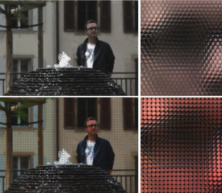
The Lenslet data represents a LF image after applying the demosaicking and the devignetting steps to a raw LF image. The Lenslet LF image is shown on the top of Figure 1. The demosaicking step is used to generate an RGB LF image from the raw LF captured by the camera. The devignetting step is applied to reduce the vignetting effect at the borders of each MI. The devignetting step in the LF Toolbox uses images that are available for each Lytro Illum LF camera that were taken using a white diffuser, or of a white scene.
Although the Lenslet data representation requires minimum pre-processing on the encoder side, in order to render an output view using the Lenslet LF image some metadata is necessary that consequently needs to be transmitted or stored in addition to the LF image itself. The metadata includes the estimated center position each MI which is extrapolated from the white images provided for each camera. This information is used to convert the Lenslet into the 4D LF data representation. Additionally, general metadata is provided for each individual image, e.g., zoom and focus settings.
2.2 4D LF data representation
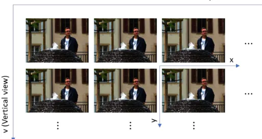
The 4D LF data representation is a format that organizes the LF image into a four-dimensional array of data that can be defined as 𝐿𝐹(ℎ, 𝑣, 𝑥, 𝑦). It comprises a stack of SAIs that is generated from the Lenslet data representation. The first two dimensions index the SAI location using horizontal and vertical coordinates, and the remaining two dimensions index the x and y spatial position within each SAI. The 4D LF data representation indexing is shown in Figure 2.
The 4D LF data representation shares the initial steps with the Lenslet data representation, where demosaicking and devignetting pre-processing steps are applied (see brief description below). After these initial steps, Lenslet to SAIs conversion is applied in two steps. In the first step, resampling, rotation and scaling is applied so all MI centers can be aligned with an integer grid of pixels. The second step applies transforming and slicing to the LF image with the aligned MI centers. In this step, the hexagonally sampled data is converted into a square based grid of MIs. After this step, the SAIs can be constructed by extracting one pixel from a fixed position, in each MI, and organizing them into a matrix. When using the Lytro Illum, 15×15 SAIs with an individual resolution of 625×434 can be extracted, from the raw LF, using the LF Toolbox. This means that the total number of pixels is increased by about 47%, when compared to the Lenslet data representation.
An optional rendering step can be applied, which may include color and gamma correction, and also rectification of each SAI. In this work, the suggested color and gamma correction matrices from JPEG Pleno were applied to each SAI, but the rectification tool was not used, in order to reduce the total amount of processing blocks in each test.
Once the LF image is converted into the 4D LF data representation, i.e., a stack of SAIs, it can be organized in several ways. For example, a single LF image with concatenated squared 15×15 pixel MIs (4DLF-MI) as in Figure 1; all the SAIs concatenated in one single frame (4DLF-SAI); or generating a so called pseudo video sequence (PVS), using the SAIs, where a scanning order like raster or spiral is used (4DLF-PVS). All these conversions are possible and reversible due to the four-dimensional indexing, which also facilitates view rendering.
Figure 1 – LF image using Lenslet (top) and 4DLF-MI (bottom) data representations, characterized by a non-integer hexagonal-based grid and an integer square-based grid, respectively
Figure 2 – 4D LF data representation indexing (image “Fountain and Vincent 2“ i.e. I09 from the EPFL LF dataset)
3. PROCESSING CHAIN FOR OBJECTIVE QUALITY ASSESSEMENT
JPEG Pleno proposes a reference processing chain to assess the coding efficiency of different LF coding solutions (see Figure 3). This processing chain aims to accommodate different LF coding solutions that may rely on different LF data representations [21]. However, objective and subjective performance evaluation is done using a common data representation: the 4D LF data representation [21]. Therefore, regardless of the coding approach, the corresponding output format must be converted into a 4D LF, organized as a stack of RGB 4:4:4 10-bit SAIs, i.e., the same format of the Reference LF image generated using the reference processing chain shown in Figure 3.
Figure 3 – JPEG Pleno reference LF processing chain [21]
The JPEG Pleno reference LF processing chain is comprised by the steps described in the previous section to generate the Lenslet and 4D LF data representation from the raw LF data. To assess the objective quality of a proposed LF image codec, it is required to encode and decode the images using a coding solution and then converting the LF image to the 4D LF data representation using a RGB 4:4:4 10 bit color format. If the proposed codec is limited to a specific LF data representation, e.g. Lenslet, and or a specific color format, e.g. YUV 4:2:0 8 bit, the processing chain needs to be adapted.
The following subsections will tackle the adaptations required by the processing chain when two data representations are tested: Lenslet and the 4D LF common data representation. Additionally, for both data representations two color subsampling formats with different bit depths are also compared, YUV 4:4:4 10 bit/sample (10-bit) and YUV 4:2:0 8 bit/sample (8-bit).
3.1 Processing chain for the Lenslet data representation
When the Lenslet data representation is used in a given codec, since it is different from the 4D LF common data representation, some adaptations to the processing chain are necessary. These adaptations will allow the output LF image to use the same data representation and color format as the Reference LF image, and therefore be comparable in terms of objective metrics. Additionally, since each codec might be designed for a specific color format, the required color conversions for the specific color format must also be included.
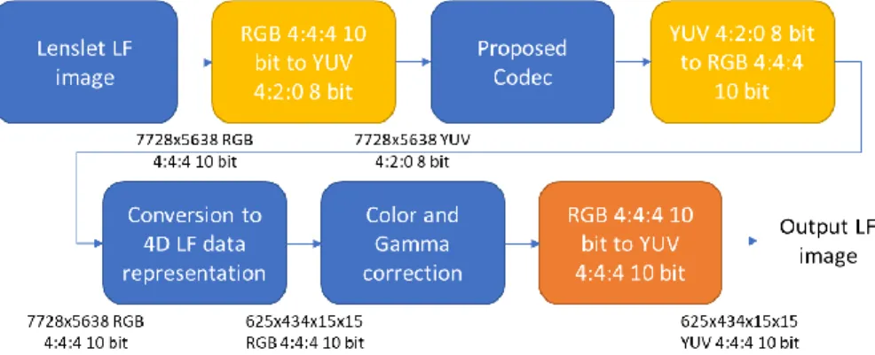
The processing chain for a Lenslet data representation with an YUV 4:4:4 10-bit format is shown in Figure 4.
Figure 4 – Processing chain to encode LF data with Lenslet data representation and YUV 4:4:4 10-bit format
In the case of Figure 4, the proposed codec uses the YUV 4:4:4 10-bit format, therefore the necessary color conversion is applied prior to the encoding step. After encoding and decoding of the lenslet LF image, a conversion to the 4D LF data representation is necessary. The provided LF Toolbox for such conversion requires the input to use RGB 4:4:4 10-bit format, therefore the decoded Lenslet LF image is converted to such specific color format and then converted to 4D LF data representation. Color and Gamma correction is applied to the 4D LF image, and finally, it is converted to YUV 4:4:4 10-bit in order to be compared with the Reference LF image in terms of objective metrics.
When a different color format is necessary, e.g., YUV 4:2:0 8-bit, the necessary changes to processing chain are shown by the yellow blocks in Figure 5.
Figure 5 – Processing chain to encode LF data using the Lenslet data representation and YUV 4:2:0 8-bit color format
In Figure 5, the encoded Lenslet LF image is in the YUV 4:2:0 8-bit format, therefore the color quality may be potentially degraded, but the amount of information to be compressed is greatly reduced.
When using the Lenslet data representation, some additional information, i.e., camera metadata [4], would be necessary to be transmitted to the decoder in order to allow a proper view rendering. Converting the Lenslet data representation into 4D LF facilitates the view rendering [4]. This metadata must include, at least, the MI center coordinates and MI size [5]. Any other alternative data representation format to 4D LF requires a processing step to convert the specific data representation to 4D LF using RGB 4:4:4 10-bit, in order to be compared with the Reference LF image.
3.2 Processing chain for the 4D LF data representation
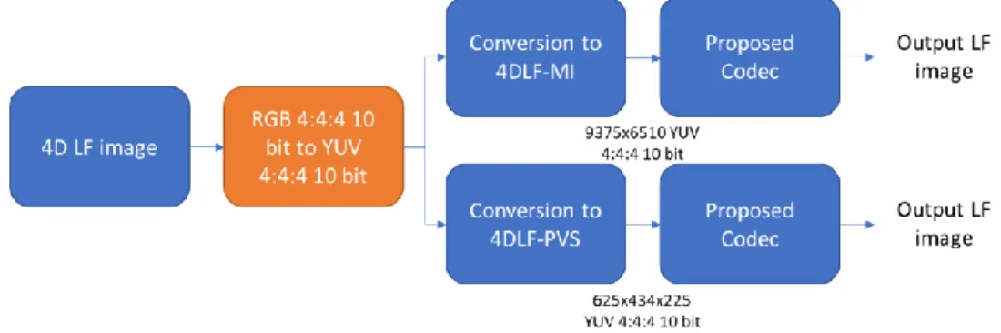
For encoding the LF image using some variation of 4D LF data representation, the processing chain is more straightforward than when using the Lenslet data representation. In Figure 6, the required processing chain for 4D LF is shown.
Figure 6 – Processing chain to encode LF data using the 4D LF data representation and YUV 4:4:4 10-bit color format
As mentioned in the previous section, 4D LF can be used in several variants. In this paper only two variants are considered: MI and PVS. The MI consists on a 2D frame with all MIs concatenated as a matrix and the 4DLF-PVS is a video sequence of SAIs using a spiral scan [10]. Although the formats are different, the conversion between both is seamless, without losing any information. However, in order to encode the LF image using the 4DLF-PVS variant, efficiently exploiting the redundancy between each SAI, a video codec is necessary.
In the case of Figure 6, the 4D LF image is converted into the color format required by the proposed codec, in this case YUV 4:4:4 10-bit. After this step, the image is converted into the 4D LF variant to be tested, either MI or 4DLF-PVS. Finally, the resulting LF data is encoded, decoded and compared with the Reference LF image. This comparison can be done directly, because these 4D LF variants can be converted to SAIs to determine the objective quality metrics. When the proposed codec is limited to the color format YUV 4:2:0 8-bit, the blocks in yellow in Figure 7 need to be added to the previously described processing chain.
In this case, since the required color format is YUV 4:2:0 8-bit, a color conversion block is added to the processing chain, after the proposed codec block. This allows the output LF image to be compared with the Reference LF image.
3.3 Comparison of Lenslet and 4D LF data representations
The following major differences between the Lenslet and 4D LF data representations may drastically impact on the objective performance assessment:
1. Camera metadata: By effectively converting the LF data into a stack of SAI, the 4D LF data representation does not require any camera metadata to perform basic rendering tasks at the decoder side, namely, view generation and focus change. However, when using the Lenslet data representation, some specific camera metadata is required to enable proper rendering tasks. This information is not standardized; however, it could include transmitting the MI size and MI centers, which are necessary to convert from the non-integer hexagonal grid to the integer squared grid of MIs.
2. LF image resolution: In the case of the Lenslet data representation, the LF image resolution will be the native resolution, i.e., 7728×5368 pixels for the Lytro Illum. However, when this format is converted to the 4D LF data representation, the number of pixels is expanded to 9375×6510 pixels, or 625×434×15×15 pixels, when using 4DLF-MI or 4DLF-PVS data representations, respectively, which represents an increase of around 47% in the amount of data to be transmitted to the decoder. Therefore, the Lenslet data representation is much more compact if camera metadata is not considered.
3. Color processing: Due to the color conversion and color and gamma correction processing steps, which are necessary for both 4D LF and Lenslet data representations, color degradation along the processing chain is likely to occur. In such case, the Lenslet data representation is likely to suffer from a more prevalent degradation of color components when compared to the 4D LF data representation, because of two main reasons: 1) The number of color conversions steps for both YUV 4:4:4 10-bit and YUV 4:2:0 8-bit is higher; 2) The Color and Gamma correction step is only performed on the decoder side after the losses introduced by the codec and by the color conversion processing steps, reducing the final color accuracy.
4. EXPERIMENTAL RESULTS
In this section, the LF data representations described in the previous sections, namely Lenslet, 4DLF-MI and 4DLF-PVS, are tested and compared. Additionally, for each LF data representation two color formats, YUV 4:4:4 10-bit and YUV 4:2:0 8-bit, are used in the codec block of the processing chain. With these combinations of LF data representation and color formats, the effects of the suggested processing chain are evaluated in terms of objective results. The codec used in these experimental tests is the HM-16.9 implementation of HEVC-RExt [25], that may use different coding profiles, depending on the combination of the LF data representation and color format. The following six scenarios, along the specific coding profiles and used processing chains, were tested:
1. Lenslet YUV 4:2:0 8-bit, using Main Intra profile and the processing chain of Figure 5; 2. 4DLF-MI YUV 4:2:0 8-bit, using Main Intra profile and the processing chain of Figure 7; 3. 4DLF-PVS YUV 4:2:0 8-bit, using Main profile and the processing chain of Figure 7;
4. Lenslet YUV 4:4:4 10-bit, using Main 4:4:4 10 Intra profile and the processing chain of Figure 4; 5. 4DLF-MI YUV 4:4:4 10-bit, using Main 4:4:4 10 Intra profile and the processing chain of Figure 6; 6. 4DLF-PVS YUV 4:4:4 10-bit, using Main 4:4:4 10 profile and the processing chain of Figure 6.
In the following subsections, the specific block settings for each processing chain is described, as well as the achieved experimental results and individual conclusions.
4.1 Color correction
The Reference LF images were generated by the reference processing chain, shown in Figure 3, using the LF Toolbox v0.4 for the Demosaicking, Devignetting and Conversion to 4D LF data representation blocks. Regarding the Color and Gamma correction blocks, the LF Toolbox was modified to accommodate the Color Correction suggested in the final version of the Call for Proposals from JPEG Pleno [21].
𝐶𝑜𝑙𝑜𝑟𝑀𝑎𝑡𝑟𝑖𝑥 = [
2.4036 −0.4913 −0.3136 −1.2089 1.6521 −0.9322 −0.1947 −0.1607 2.2458
]; 𝐶𝑜𝑙𝑜𝑟𝐵𝑎𝑙𝑎𝑛𝑐𝑒 = [1 1 1]; 𝐺𝑎𝑚𝑚𝑎 = 1 (1)
After applying the Color and Gamma correction defined by (1), the Reference LF image was generated and ready to be compared with the output LF images, either from the Lenslet or 4D LF processing chains.
4.2 Chroma and bit depth upsampling and downsampling
In order to generate output LF images in the 4D LF data representation to be compared with the Reference LF image, the processing chains described in the previous section are used. Regardless of using the Lenslet or 4D LF data representations, the color conversion blocks are necessary to convert the LF images to YUV 4:4:4 10-bit or YUV 4:2:0 8-bit.
The conversion from RGB to YUV is done using the Recommendation ITU-R BT.601-5, however in the latest common test conditions document released by JPEG Pleno the Recommendation ITU-R BT.709-6 is used [22]. Although the results are slightly different using different color conversion standards, the conclusions in this paper still hold, since the same color conversion standard is applied in both reference processing chain and proposed codec processing chain.
Additionally, subsampling the chroma components from YUV 4:4:4 to YUV 4:2:0 and upsampling from YUV 4:2:0 is done using scripts provided for the ICME 2016 Light Field Challenge [26]. Bit depth downsampling from 10-bit to 8-bit is performed by truncating the two least significant bits. Bit depth upsampling from 8-bit to 10-bit is done by multiplying the pixel value in 8 bits by 4.
4.3 Objective performance assessment
In order to access the objective performance of the proposed codec, in this case HEVC-RExt, for six different scenarios, it is necessary to: 1) calculate the number of bits per pixel the codec uses to encode the LF image and the metadata necessary to perform image rendering; 2) calculate the average PSNR of each rendered view, in comparison to the views rendered from the Reference LF image.
Since the EPLF dataset is based on LF images, captured using the Lytro Illum LF camera, the number of possible views that can be extracted using the LF Toolbox is 15×15. However, since the outer views are mostly unusable, JPEG Pleno recommends that only the results for the inner 13×13 views are evaluated [22]. Because of this, when the 4D LF data representation is used, the outer views are discarded before the encoding step, so effectively, only 13×13 views are encoded. Each view has a resolution of 625×434 pixels, thus the total number of pixels is 45 841 250 [22]. Although it is a significant reduction in the number of views, i.e., from 225 views to 169 views, consequently, the spatial resolution used to encode the 4D LF data representation is still, roughly, 11% larger than the one used by the Lenslet data representation. The number of bits per pixel is calculated by dividing the number of bits used to encode the LF image by the total number of pixels.
Likewise, the average PSNR only considers the inner 13×13 views. As it was explained in the previous section, regardless of the used data representation, the LF images that reach the decoder side are converted into 4D LF, with the color format YUV 4:4:4 10-bit, to be compared with the Reference LF image. Thus, regardless of the proposed codec limitations in terms of color format and LF data representation, the six different scenarios can be compared. The objective quality is obtained by calculating the individual PSNR-YUV for each view, comparing the output and the Reference LF image, and then averaging the 13×13 individual PSNR-YUV values. The PSNR-YUV is calculated by Eq. (2).
𝑃𝑆𝑁𝑅𝑌𝑈𝑉 =6 ∗ 𝑃𝑆𝑁𝑅𝑌+ 𝑃𝑆𝑁𝑅𝑈+ 𝑃𝑆𝑁𝑅𝑉
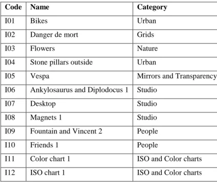
The EPFL dataset [23] was used for testing, as shown in Table 1.
Table 1 – General information about the EPFL LF dataset
Code Name Category
I01 Bikes Urban
I02 Danger de mort Grids
I03 Flowers Nature
I04 Stone pillars outside Urban
I05 Vespa Mirrors and Transparency I06 Ankylosaurus and Diplodocus 1 Studio
I07 Desktop Studio
I08 Magnets 1 Studio
I09 Fountain and Vincent 2 People
I10 Friends 1 People
I11 Color chart 1 ISO and Color charts I12 ISO chart 1 ISO and Color charts
Every image from the EPFL dataset was encoded and decoded using HEVC-RExt, with the appropriate profile. The QPs used for the Lenselt and 4DLF-MI data representations were 22, 27, 32, 37 and 42, and the QPs used for 4DLF-PVS were 17, 22, 27, 32, 37. The achieved results for this selection of QPs produce bitrates within the target bit rates proposed by JPEG Pleno, in the Common Test Conditions Document, i.e., between 0.001 bpp and 0.75 bpp [22] .
4.4 Analysis of the experimental results
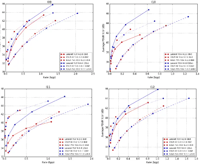
The experimental results for the full EPFL dataset [23] using HEVC-RExt codec, in the six scenarios previously described are shown in Figure 8.
Figure 8 - Rate-Distortion results comparing all six combinations of LF data representations and color formats for the twelve LF images from the EPFL dataset
LF data representation comparison
When comparing the results shown in Figure 8 in terms of LF data representation, it is possible to observe that the least efficient LF data representation is the 4DLF-MI. In all images, with the exception of I11, the 4DLF-MI has the worst performance in comparison with the other LF data representations, across all the tested bitrates. The redundancy that exists within neighboring MIs is not exploited by HEVC which explains the poor efficiency for this LF data representation. The 4DLF-MI data representation is expected to perform significantly better if using a prediction tool to exploit the MI redundancy in HEVC [14][15].
The two remaining LF data representations, Lenslet and 4DLF-PVS are much more efficient, however the comparison between both shows that the most efficient LF data representation depends on several factors. When comparing these two LF data representations, it is worth reinforcing the fact that no metadata is being considered for the Lenslet data representation, and that the 4D LF based data representations generate roughly 11% more pixels to encode, in comparison with the Lenslet data representation.
If the color format is YUV 4:2:0 8-bit (red curves), the 4DLF-PVS is more efficient in comparison to the Lenslet for most cases, the exceptions are I02, I03 and I04. However, if the color format is YUV 4:4:4 10-bit (blue curves), the Lenslet is more efficient in 7 out of the 12 images, when compared to the 4DLF-PVS.
If the comparison is done between the Lenslet and 4DLF-PVS, considering both tested color formats YUV 4:4:4 10-bit and YUV 4:2:0-8 bit, the results depend on the image content. 4DLF-PVS tends to be more efficient for Studio, Mirrors and Transparency, and ISO and Colour Charts categorized images in the EPFL dataset, these images include I05, I06, I08, I09, I11 and I12. However, the remaining dataset would have to be tested to confirm this assumption, which will be done in future work. From the results one can also conclude that the 4DLF-PVS tends to be more efficient when compared to the Lenslet data representation at lower bitrates.
Color format comparison
When strictly comparing color formats within each LF data representation, one can conclude that there is a clear tendency of the 4D LF data representations to be more efficient if encoded using YUV 4:2:0 8-bit color when compared to the YUV 4:4:4 10-bit. This can be seen in both 4DLF-PVS data representation, for all images, and for 4DLF-MI data, for all images with the exception of I07 and I10 where the YUV 4:4:4 10-bit is slightly more efficient. This tendency is even more notorious for the average PSNR-Y, instead of the average PSNR-YUV.
The exact opposite tendency can be seen in the case of the Lenslet data representation, where using YUV 4:4:4 10-bit is more efficient than using YUV 4:2:0 8-bit. This tendency can be seen for every tested image. Additionally, the exact opposite tendency is also seen if the average PSNR-Y is used instead of the average PSNR-YUV, i.e., the difference in performance between YUV 4:4:4 10-bit and YUV 4:2:0 8-bit are smaller when using average PSNR-Y.
These results can be justified with the color correction and color conversions processing blocks for both LF data representations. In the case of 4D LF data representation, the color correction processing step is applied early in the processing chain before any color conversion or encoding takes place. The color conversion and encoding steps add distortion to the LF image luma and chroma components. However, since the color correction was applied before chroma subsampling and encoding, in the case of YUV 4:2:0 8-bit, the objective quality of these components is higher.
In the case of the Lenslet data representation, more color conversions steps are necessary, especially when YUV 4:2:0 8-bit color format is used, which adds more distortion to the chroma components. Additionally, the color correction step is only applied on the decoder side, after the chroma components are distorted by color conversion and encoding steps.
Maximum objective quality
When an alternative LF data representation and color format is used with 4D LF RGB 4:4:4 10-bit, additional processing blocks are necessary, as described in the last section. These additional processing blocks will add irreversible distortion to the LF image, regardless of the coding option that is used. In order to assess the maximum objective quality, the processing chains used in the last section for the six possible scenarios are reused, but removing the proposed codec processing block. The maximum objective quality for both Lenslet and 4D LF data representations, using YUV 4:4:4 10-bit and YUV 4:2:0 8-bit color formats, is shown in Table 2 for the average PSNR-Y and Table 3 for the average PSNR-YUV.
Table 2 – Maximum objective quality measured in Average PSNR-Y (bold and italic PSNR values correspond to the maximum and minimum, respectively).
Avg. PSNR-Y
(dB) I01 I02 I03 I04 I05 I06 I07 I08 I09 I10 I11 I12 AVG.
Lenslet YUV 4:2:0 8 bit 51.18 54.87 52.08 56.18 51.04 55.63 45.51 54.83 53.36 46.49 44.02 51.34 51.38 4D LF YUV 4:2:0 8 bit 55.98 56.77 56.45 55.94 56.15 55.19 53.04 55.26 55.43 54.36 55.30 55.40 55.44 Lenslet YUV 4:4:4 10 bit 64.76 65.45 65.47 64.51 65.38 65.54 65.32 65.54 64.13 63.31 63.95 63.76 64.76 4D LF YUV
4:4:4 10 bit Inf. Inf. Inf. Inf. Inf. Inf. Inf. Inf. Inf. Inf. Inf. Inf. Inf.
Table 3 – Maximum objective quality measured in Average PSNR-YUV (bold and italic PSNR values correspond to the maximum and minimum, respectively).
Avg.
PSNR-YUV (dB) I01 I02 I03 I04 I05 I06 I07 I08 I09 I10 I11 I12 AVG.
Lenslet YUV 4:2:0 8 bit 48.50 51.41 49.56 52.39 48.43 51.87 44.47 51.35 50.07 44.72 42.72 49.06 48.71 4D LF YUV 4:2:0 8 bit 52.85 53.86 53.29 53.17 53.31 52.47 50.49 52.61 52.22 51.99 51.83 52.61 52.56 Lenslet YUV 4:4:4 10 bit 62.88 63.39 63.46 62.67 63.36 61.92 63.75 61.92 62.40 61.82 62.32 62.12 62.67 4D LF YUV
4:4:4 10 bit Inf. Inf. Inf. Inf. Inf. Inf. Inf. Inf. Inf. Inf. Inf. Inf. Inf.
From Table 2 and Table 3 it is possible to conclude that the processing chain for the 4D LF data representation has a smaller impact on the final average PSNR. This is justified by the fact that the alternative LF data representations, in this case the Lenslet, need additional processing steps that introduce distortion to the LF image.
The average PSNR-Y is higher than the average PSNR-YUV for every case that was tested, which is justified by the necessary color conversions that are applied in each individual processing chain. Although this is true for both Lenslet and 4D LF data representations, in the case of the Lenslet data representation, the average PSNR-YUV reaches values as low as 42 dB, when YUV 4:2:0 8-bit color format is used and 50 dB, when YUV 4:4:4 10-bit color format is used.
The average PSNR-YUV for all images is roughly 4 dB higher for the 4D LF data representation in comparison with the Lenslet data representation. This confirms that the Lenslet data representations is more affected by the processing chain than the 4D LF data representation, in terms of both luma and chroma components.
In this case, no distinction is done between 4DLF-MI and 4DLF-PVS, because the conversion between both of the 4D LF data representation is reversible and can be applied at any point in the processing chain.
In the case of the 4D LF data representation used with YUV 4:4:4 10-bit color format, when removing the proposed codec processing block, the processing chain becomes identical to the reference processing chain, consequently, the PSNR is infinite for every case.
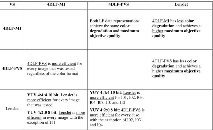
Summary of the experimental results analysis
The summary of the experimental results analysis is shown on Table 4. The presented table is a diagonal table, where the upper triangle shows the comparisons between the tested LF data representations in terms of color degradation and maximum objective quality. On the other hand, the lower triangle shows the comparisons between the tested LF data representation in terms of achieved coding efficiency for each color format that was tested.
Table 4 - Summary of experimental results analysis
VS 4DLF-MI 4DLF-PVS Lenslet
4DLF-MI
Both LF data representations achieve the same color degradation and maximum objective quality
4DLF-MI has less color degradation and achieves a higher maximum objective quality
4DLF-PVS
4DLF-PVS is more efficient for every image that was tested regardless of the color format
4DLF-PVS has less color degradation and achieves a higher maximum objective quality
Lenslet
YUV 4:4:4 10 bit: Lenslet is more efficient for every image that was tested
YUV 4:2:0 8 bit: Lenslet is more efficient in every image with the exception of I11
YUV 4:4:4 10 bit: Lenslet is more efficient for I01, I02, I03, I04, I07, I10 and I12
YUV 4:2:0 8 bit: 4DLF-PVS is more efficient for every case with the exception of I02, I03 and I04
5. CONCLUSIONS
In this paper, an in-depth comparison of the effects of using existing LF data representations, considering different color formats, using JPEG Pleno guidelines, was presented and analyzed. Lenslet, 4DLF-MI and 4DLF-PVS data representations were compared using YUV 4:4:4 10-bit and YUV 4:2:0 8-bit color formats. Consequently, the six individual combinations using the mentioned LF data representations and color formats were exhaustively tested and compared. Each combination of LF data representation and color format requires a specific processing chain, in order to be encoded and decoded by the proposed codec, and finally converted to the common format for objective quality assessment, namely 4D LF YUV 4:4:4 10-bit.
The experimental results show that, for the selected codec, i.e., HEVC-RExt, the LF data representation that achieves the lowest coding efficiency is the 4DLF-MI, regardless of the color format. Although the same number of pixels are being encoded, the 4DLF-PVS achieves a higher coding efficiency, when compared to 4DLF-MI, essentially because the inter-view redundancy is exploited by the temporal predictions tools available in HEVC. The comparison between the Lenslet and 4DLF-PVS data representations required a more in-depth analysis of the experimental results.
The 4DLF-PVS data representation is more efficient, in most cases, than the Lenslet data representation when the YUV 4:2:0 8-bit color format is used. If the color format YUV 4:4:4 10-bit is used, the Lenslet data representation is more efficient than the 4DLF-PVS in seven out of twelve cases. If the best performing color format is selected for each LF data representation, i.e., Lenslet using a YUV 4:4:4 10-bit color format and 4DLF-PVS using a YUV 4:2:0 8-bit color format, the most efficient LF data representation depends on the content of the image. In this case, using 4DLF-PVS YUV 4:2:0 8-bit appears to be more efficient than Lenslet YUV 4:4:4 10-bit when encoding LF images from the EPFL dataset, assigned to Studio, Mirrors and Transparency and ISO and Colour Charts categories. However, in order to verify this assumption, the full dataset would have to be tested.
The Lenslet data representation benefits from the color format YUV 4:4:4 10-bit while both 4D LF data representations produce better results when YUV 4:2:0 8-bit color format is used. This conclusion can be further verified by comparing the results using the average PSNR-Y and average PSNR-YUV. When analyzing the results for average PSNR-Y, the efficiency gains of the YUV 4:2:0 8-bit color format are even more notorious than when using the average PSNR-YUV. However, when performing the same analysis using the Lenslet data representation, the opposite tendency occurs; the efficiency gains of the YUV 4:4:4 10-bit are lower when using the average PSNR-Y, instead of average PSNR-YUV. When analyzing the results for the maximum quality of each of the six test scenarios, with the different LF data representations and color formats, one can conclude that the maximum quality is lower when the Lenslet data representations is used. When the YUV 4:2:0 8-bit color format is used, the maximum quality using the average PSNR-YUV can be as a low as 42 dB. When analyzing the maximum quality results using the average PNSR-Y metric, the objective quality is always higher, with an average increase of about 3 dB. These results lead to the conclusion that, an alternative LF data representation like Lenslet, although more compact than the 4D LF variants, is going to suffer more color degradation due to the more extensive processing chain.
In general, a large variety of results were reproduced by testing six possible scenarios using a common codec. A further study must be conducted to evaluate the performance when comparing different codecs. One might assume that the higher coding efficiency of one codec over another may come from technical features, but one must take into account the effects of different LF representations or color formats. Also, an alternative LF data representation is most likely to produce a lower maximum quality when compared to the 4D LF, because of the additional processing steps necessary to convert to 4D LF.
Future work will include testing the full EPFL dataset, in order to better distinguish the different efficiencies achieved with Lenslet and 4DLF-PVS. An additional state of the art codec is also going to be tested that includes an efficient prediction tool to encode LF images.
REFERENCES
[1] T. Georgiev and A. Lumsdaine, “Rich Image Capture with Plenoptic Cameras,” in IEEE International Conference on Computational Photography, Cluj-Napoca, Romania, Aug. 2010, pp. 1–8.
[2] A. L. Todor G. Georgiev, “Focused plenoptic camera and rendering,” J. Electron. Imaging, vol. 19, pp. 19-19–11, Apr. 2010.
[3] Lytro Illum, https://illum.lytro.com/illum/specs.
[4] I. Viola, M. Řeřábek, and T. Ebrahimi, “Comparison and Evaluation of Light Field Image Coding Approaches,” IEEE J. Sel. Top. Signal Process., vol. 11, no. 7, pp. 1092–1106, Oct. 2017.
[5] D. G. Dansereau, O. Pizarro, and S. B. Williams, “Decoding, Calibration and Rectification for Lenselet-Based Plenoptic Cameras,” in 2013 IEEE Conference on Computer Vision and Pattern Recognition, Jun. 2013, pp. 1027– 1034.
[6] G. Alves, F. Pereira, and E. A. B. da Silva, “Light field imaging coding: Performance assessment methodology and standards benchmarking,” in 2016 IEEE International Conference on Multimedia Expo Workshops (ICMEW), Jul. 2016, pp. 1–6.
[7] G. J. Sullivan, J. R. Ohm, W. J. Han, and T. Wiegand, “Overview of the High Efficiency Video Coding (HEVC) Standard,” IEEE Trans. Circuits Syst. Video Technol., vol. 22, no. 12, pp. 1649–1668, Dec. 2012.
[8] J. B. Jianle Chen Elena Alshina, Gary J. Sullivan, Jens-Rainer Ohm, Algorithm description of Joint Exploration Test Model 3 (JEM3), ISO/IEC JTC1/SC29/WG11/N16276. 2016.
[9] F. Dai, J. Zhang, Y. Ma, and Y. Zhang, “Lenselet image compression scheme based on subaperture images streaming,” in IEEE International Conference on Image Processing, Sep. 2015, pp. 4733–4737.
[10] A. Vieira, H. Duarte, C. Perra, L. Tavora, and P. Assuncao, “Data formats for high efficiency coding of Lytro-Illum light fields,” in International Conference on Image Processing Theory, Tools and Applications, Nov. 2015, pp. 494– 497.
[11] D. Liu, L. Wang, L. Li, Z. Xiong, F. Wu, and W. Zeng, “Pseudo-sequence-based light field image compression,” in IEEE International Conference on Multimedia Expo Workshops, Jul 2016, pp. 1–4.
[12] C. Conti, L. D. Soares, and P. Nunes, “HEVC-based 3D holoscopic video coding using self-similarity compensated prediction,” Signal Process. Image Commun., vol. 42, pp. 59–78, Mar. 2016.
[13] C. Conti, P. Nunes, and L. D. Soares, “Light field image coding with jointly estimated self-similarity bi-prediction,” Signal Process. Image Commun., vol. 60, pp. 144–159, Feb. 2018.
[14] R. Monteiro et al., “Light field HEVC-based image coding using locally linear embedding and self-similarity compensated prediction,” in IEEE International Conference on Multimedia Expo Workshops, Jul. 2016, pp. 1–4. [15] R. J. Monteiro, P. Nunes, N. Rodrigues, and S. M. M. de Faria, “Light Field Image Coding using High Order Intra
Block Prediction,” IEEE J. Sel. Top. Signal Process., vol. 11, no. 7, pp. 1120-1131 , Oct. 2017.
[16] L. F. R. Lucas et al., “Locally linear embedding-based prediction for 3D holoscopic image coding using HEVC,” in European Signal Processing Conference, Lisbon, Portugal, Sep. 2014, pp. 11–15.
[17] J. Chen, J. Hou, and L. P. Chau, “Light Field Compression With Disparity-Guided Sparse Coding Based on Structural Key Views,” IEEE Trans. Image Process., vol. 27, no. 1, pp. 314–324, Jan. 2018.
[18] X. Jiang, M. L. Pendu, R. A. Farrugia, S. S. Hemami, and C. Guillemot, “Homography-based low rank approximation of light fields for compression,” in 2017 IEEE International Conference on Acoustics, Speech and Signal Processing (ICASSP), Mar. 2017, pp. 1313–1317.
[19] X. Jiang, M. L. Pendu, and C. Guillemot, “Light field compression using depth image based view synthesis,” in Jul. 2017 IEEE International Conference on Multimedia Expo Workshops (ICMEW), 2017, pp. 19–24.
[20] JPEG Pleno Abstract and Executive Summary, Sydney, ISO/IEC JTC 1/SC 29/WG1 N6922, Feb. 2015.
[21] JPEG Pleno Call for Proposals on Light Field Coding, Switzerland, ISO/IEC JTC 1/SC29/WG1N74014, Jan. 2017. [22] JPEG Pleno Light Field Coding Common Test Conditions, Germany, ISO /IEC JTC 1/SC 29 /WG 1 M80008, Jul.
2018.
[23] EPFL Light-field image dataset, http://mmspg.epfl.ch/EPFL-light-field-image-dataset. [24] Light Field Toolbox v0.4, http://dgd.vision/Tools/LFToolbox/ .
[25] D. Flynn et al., “Overview of the Range Extensions for the HEVC Standard: Tools, Profiles, and Performance,” IEEE Trans. Circuits Syst. Video Technol., vol. 26, no. 1, pp. 4–19, Jan. 2016.
[26] ICME 2016 Grand Challenge: Light-Field Image Compression, http://mmspg.epfl.ch/files/content/sites/mmspl/files/ shared/LF-GC/CFP.pdf .