Design and Evaluation of Swing Phase Controllers
for Single-axis Knee
Solomon Seid, S. Sujatha*, Sujatha Chandramohan
Mechanical Engineering Department Indian Institute of Technology Madras Chennai 600036, India
E-mails: [email protected],[email protected],
*Corresponding author
Received: December 28, 2015 Accepted: July 19, 2016
Published: September 30, 2016
Abstract: A prosthetic swing-phase control mechanism simulates the action of thigh musculature to aid in increased gait function. In this work, a hydraulic damper and a magnetorheological (MR) damper are designed as controllers with an objective of evaluating their performance in controlling swing-phase damping in an above-knee prosthesis. Parametric models are utilized to represent dynamic properties of the dampers. Based on the models, control parameters that govern damping force and displacement of the dampers are identified. Parameters of the dampers are determined through optimization that minimizes the error between the prosthesis knee angle trajectories and a desired knee angle trajectory for normal level ground walking from experimental data. Experimental data of thigh and hip motions are introduced as inputs into a dynamic system to determine sets of control parameters. Furthermore, input thigh motion is also deviated to evaluate robustness of the controllers in real application. Comparison of the desired knee angle trajectory with those of the knee angle trajectories obtained from control parameters is done with respect to maximum achievable knee flexion angle, duration of swing phase, shank velocity at the end of swing phase and mean angle difference. Evaluation results of the dampers show a better competence of MR damper over hydraulic damper.
Keywords: Swing phase control, Magnetorheological damper, Hydraulic damper, Single-axis knee, Prosthetics.
Introduction
Based on the control mechanism for prosthesis stiffness during swing phase, prostheses are categorized as passive, semi-active, and active. In the swing phase, muscle actions provide/dissipate power for the biological knee joint in two ways: the active force is applied by muscle action, and variable stiffness is also provided by muscles. When the prosthetic knee utilizes the latter action without any automated control over prosthesis stiffness, it is called passive prosthetic knee, whereas if a microcontroller is employed to control the changes in the knee impedance (damping and/or stiffness) based on sensory information, it is classified as semi-active prosthetic knee. When prosthetic knees are tethered to an external power supply and microcontroller to control and alter the impedance of the actuators based on sensory information, then it is usually known as active/powered prosthetic knee.
Numerous studies have been done on swing-phase control mechanisms and their evaluation. Dundass et al. [8] developed a dynamic model of transfemoral amputee gait to investigate deterioration of a hydraulic knee controller. Furse et al. [9] enhanced the performance of swing phase for friction-based passive single-axis knee by incorporating two springs in series. Unal et al. [26] developed a passive mechanism using three elastic storage elements based on the concept of power flow in the human gait. Dabiri [4] designed a passive controller for hydraulic damper for swing phase of single axis knee; however, the controller resulted in a very large deviation of knee flexion angle from the normal one and hence the designed controller was reported to perform poorly in terms of ground clearance. Tahani and Karimi [24] proposed a simple dynamic model of prosthesis using torsional spring and optimized control parameters for swing phase motion. Suzuki [22] performed dynamic optimization of a musculoskeletal model of residual limb to get optimal knee joint friction value for a passive prosthetic knee such that muscle metabolic energy expenditure is minimized during swing phase. Hong-Liu et al. [31] developed a dynamic model of the swing phase for an intelligent prosthetic leg system, based on the control parameters of a nonlinear hydraulic damper, to identify the dynamic interaction between the swing speed and the opening of needle valve at the damper. Zhang and Agrawal [32] proposed a transfemoral prosthesis with an actuated knee joint and a passive ankle joint that produces nearly natural walking during swing phase. Some studies compare the performance of microprocessor-controlled knee systems to conventional hydraulic and pneumatic systems [5-7, 13-14].
Magnetorheological (MR) damper is a semi-active device, which uses a controllable fluid, MR fluid, and is widely applied in variable damping knees [11, 15-16]. MR fluid is a suspension of micrometer-sized magnetic particles in a carrier fluid, which is usually a type of oil. In the absence of an applied field, the particles are distributed randomly and the fluid exhibits quasi-Newtonian behavior. When the MR fluid is subjected to a magnetic field, the particles become magnetized and they start to behave like tiny magnets. The interaction between the resulting induced dipoles causes the particles to aggregate and form fibrous structures within the carrier liquid, changing the rheology of the MR fluid to a near solid state. These chain-like structures restrict the flow of the MR fluid, thereby increasing the viscous characteristics of the suspension. The mechanical energy needed to yield these chain-like structures increases nonlinearly with an increase in the applied magnetic field, resulting in a field-dependent yield stress. The process is fully variable and reversible. By controlling the strength of the magnetic field, the shear strength of the MR fluid can be altered, so that resistance to the MR flow can be varied. Some researchers have studied reliability of MR damper application in the rehabilitation area [2-3, 10, 28-30].
prosthetic knee use. Thus, this work primarily aims to fill this gap. Accordingly, a simple mechanism of single-axis knee joint incorporating the damper is considered during the swing phase. The dampers are designed independently with the objective of controlling swing-phase damping in above-knee prosthesis. Control parameters are optimized so as to achieve an optimal track of the swing phase trajectory. Subsequently, performance of the dampers is evaluated through computer simulation. Moreover, most accessible low-technology, affordable prosthetic devices such as ICRC knee, M1 Knee and Jaipur knee [12, 18, 23] are without extension assist systems, while other technologies, which incorporate some level of resistance like springs and/or friction, have limitations in ensuring the friction levels or spring stiffness to provide adequate swing-phase control. Therefore, this work also targets contributing towards an improvement of swing phase of gait cycle by designing simple, optimized, low-technology, fluid-based swing phase controllers which allow an amputee to achieve near normal swing phase duration, normal knee flexion and decreased terminal impact. Prominently, this work develops a methodology of characterizing dampers through simulation for prosthetic knee use.
Single axis prosthetic knee incorporating damper
The single-axis knee in focus is a mechanism with one degree of freedom which is to be attached to the socket housing the residual limb of a trans-femoral amputee. In designing the controllers for this knee, the thigh motion from experimental data is provided to the dynamic system model to achieve a desired shank motion during the swing phase of the walking cycle. The motion is accomplished by incorporating and controlling the dampers independently.
Dynamic system modelling
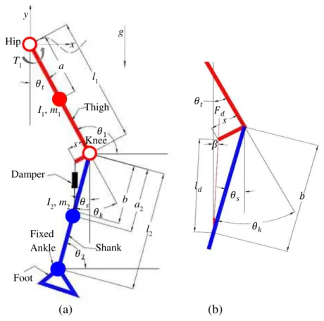
The knee is modeled as a single-axis knee with the damper as shown in Fig. 1(a).
Fig. 1 (a) The amputee’s swing leg model and (b) damper force resolution �
� ��
fd
s
�
�
�
�
g x
y
Hip
� a
l1
Thigh
�
Knee
s
Damper
Foot Fixed Ankle �
Shank
� b
�
a2
l2 I1, m1
I2, m2 T1
The ankle is assumed to be rigid. The swing leg of the amputee is modeled as a two-link rigid body chain representing the thigh and the shank in sagittal plane motion. In Fig. 1(a), subscripts 1 and 2 represent the thigh and shank respectively, mi are the masses, ai are the distances of the
mass centres from the respective proximal joints, Ii are the moments of inertia, li are lengths
and θi are the absolute angles of thigh and shank from the horizontal; θt and θs are the
corresponding absolute angles of thigh and shank respectively from the vertical, s is the offset between the knee centre and location of attachment of damper piston on the thigh, θk is the knee
angle, ld is the length of the damper and b is the distance between the knee centre and location
of the damper attachment on the shank. xh is the horizontal movement of hip and yh is the vertical
movement of hip and T1 is hip torque.
Assuming that at each joint there is no friction and using Lagrange’s formulation, one can
develop the equation of motion in the following form:
D C , G (1)
where the inertial matrix D is:
1 12 1
2 12
2 1 2
22 1 2 2 2 2
cos
cos
t s
t s
m a I m l m l a D
m l a m a I
,
the Centripetal and Coriolis terms are
2 2 1 2
2 2 1 2
sin ,
sin
s t s
t t s
m l a C
m l a
,
gravitational torque and hip acceleration terms are
2 1 1 2
2 2
( ) sin cos sin
sin cos sin
t h t h t
s h s h s
m l m a g x y
G
m a g x y
,
input vector of the hip and knee torques are
1 sin
, and vector of the thigh and shank angles is sin
d s t
d s s
T F b
F b .
The damper’s length is a variable, ld, and the damper’s upper part is connected to the lower
perpendicular posterior extension of the thigh through a pin joint at length s from the
thigh-knee line, and the damper’s lower part is connected with the shank at an offset b from the thigh-knee
on knee‐shank line. Considering the standard swing motion position adopted from [27], damping force, Fd, lies along the line connecting the two pin joints of the damper making angle
β from the vertical.
Therefore, considering Fig. 1(b), angleβ, deviation of damping force, Fd, can geometrically be
1 o
1 sin
cos 90
1 2 sin
k t k b s b b s s . (2)
In the computation of the dynamic equations of motion, the hip torque generated and the thigh angle of a normal person are known inputs. Therefore, in controlling the knee angle, it is the second row of Eq. (1) that needs to be considered for further computation. Hence, after simplifying the equation, Eq. (3) has been developed as shown below:
sin cos sin
s d s s s
L F M N P , (3)
where
2 2 2 2
2 2
m a I
L m a ,
2
1cos t t sin1 t t h
N l l x ,
2
1sin t t cos1 t t h
P l l g y , and
2 2 b M m a .
MR damper model
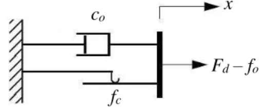
The behavior of viscoplastic MR damper is commonly represented by an idealized mechanical model, the Bingham model [21], as shown in Fig. 2. Accordingly, this model is adopted here to represent the behavior of MR damper. The model consists of the rheological structures, on which the Bingham model is based, there is a Coulomb friction element placed parallel to the
dashpot. According to Bingham’s MR damper model, for non-zero piston velocities, x, the
damping force, Fd, generated can be expressed as:
sgnd c o o
F f x c x f , (4)
where co is the damping coefficient, fc is the frictional force, which is related to the fluid yield
stress, and fo is an offset in the force to account for the nonzero mean observed in the measured
force due to the presence of the accumulator. The last simplification in the model (Fig. 2) results from the assumption that the elasticity replacing the accumulator activity has low stiffness and linear characteristics.
Fig. 2 Bingham model of a controllable damper
Hydraulic damper model
The hydraulic damper is modeled as a spring-damper element [4, 20], as shown in Fig. 3, where K is the spring stiffness and C is the damping coefficient; x is the damper length which can be determined as a geometric function of the knee angle and offset length of attachments of the
co x
Fd– fo
damper with the shank and thigh; lo is the spring undeformed length and x is the time derivative
of the damper length, x, with respect to time.
Fig. 3 Hydraulic damper model
Therefore, the resultant force of the spring and damper generated by the device is given by:
,d o
F K x l Cx (5)
2 2
where: x s b 2 sinsb k .
Solution method
Based on the dampers’ models, three control parameters can be identified and defined as a vector, p, for each damper, i.e. p = [co, fc, fo] for MR damper and p = [K, lo, C] for hydraulic
damper. The experimental data for normal hip, thigh and shank motions taken from [27], are shown in Fig. 4. For the given input experimental data, Eq. (3) has a unique solution of shank angle trajectory and hence prosthetic knee angle trajectory is defined. Therefore, the control parameters of the dampers should be selected such that the knee angle trajectory for the swing phase should match the experimental knee angle trajectory and this is achieved by feeding an appropriate input data set to the dampers. This involves formulating an optimization problem, which will minimize the error between the expected shank angle (θse) from experimental data
and computed shank angle (θsc) from the dynamic equation of motion. Moreover, variation in
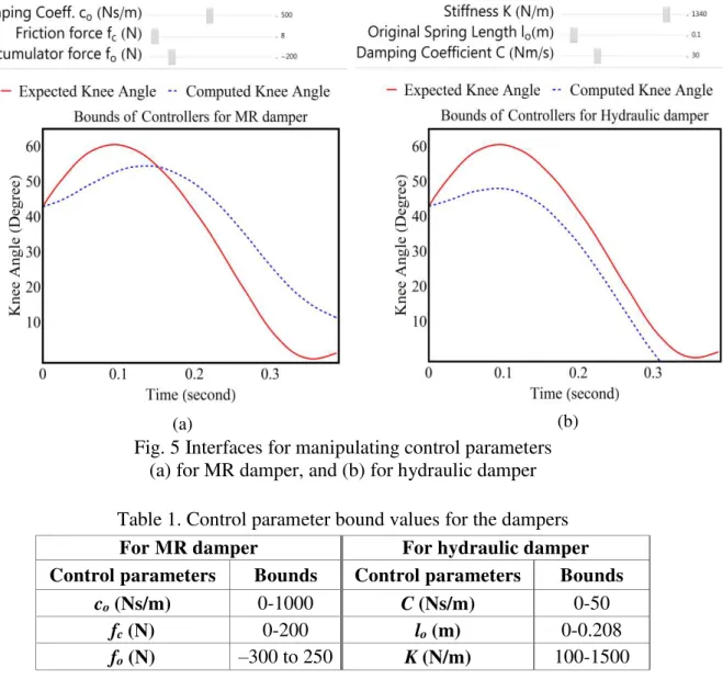
control parameters affects the characteristics of the dampers and hence the swing phase trajectory of prosthetic leg. Therefore, for a better search and enhanced computation in the process of finding optimal values, effects of each control parameter on the swing phase trajectory of knee angle are also observed by keeping the other control parameters fixed at certain local optimum values and varying any one of the control parameters such that the computed knee angle curve better approximates the expected knee angle curve. For this purpose, an interface has been developed to interactively manipulate the control parameters for each damper model in MathematicaTM software environment as shown in Fig. 5. Subsequently, upper and lower boundaries of each control parameter that are found to be better are chosen, Table 1, and used as constraints in the optimization problem.
C
K x
Fig. 4 Input experimental data from [27]
Hence, the optimization problem may be defined as:
2min ,
f
o t
se sc
p
t
R p t p t dt
(6)Subjected to: Lower Bounds Upper Bounds p ,
Fig. 5 Interfaces for manipulating control parameters (a) for MR damper, and (b) for hydraulic damper
Table 1. Control parameter bound values for the dampers
For MR damper For hydraulic damper
Control parameters Bounds Control parameters Bounds
co (Ns/m) 0-1000 C (Ns/m) 0-50
fc (N) 0-200 lo (m) 0-0.208
fo (N) –300 to 250 K (N/m) 100-1500
Numerical algorithms for constrained nonlinear optimization are broadly categorized into gradient-based methods and direct search methods. Gradient-based methods use first derivatives or second derivatives. On the other hand, direct search methods of numerical algorithms for constrained nonlinear optimization problem such as differential evolution do not use derivative information and are more tolerant to the presence of noise in the objective function and constraint. Differential evolution is a simple stochastic function global minimizer which is also computationally expensive, but is relatively robust and works well for such kind of coupled system of equations. Hence, it is used to optimize the control parameters in MathematicaTM software using default set of values for the same.
Then, after numerically determining the optimal control parameters for both dampers, the angular velocity of shank is compared with that of the normal person, such that it is within acceptable range to be stopped by an extension bumper to bring the knee angle to zero around the end of swing phase. Moreover, symmetry of the resultant swing phase trajectories is compared with that of the normal one in terms of swing phase durations and knee flexion angles. At this stage, for both dampers, controller parameters are optimized for a proper shank motion in the swing phase when thigh tracks a normal level walking trajectory. But this may not always be the case; an amputee might experience some other kind of thigh motion, hence it is required to check the performance of the dampers equipped with such optimal controlling parameters, when thigh motion deviates from the expected ideal trajectory. Thus, using optimal control
parameters, the performance of the controllers is further simulated to see how they behave when the input thigh motion is deviated from what is given.
Results
Experimental data needed for the computation, adopted from [27], are taken for the normal ground level walking of a person with 56.7 kg body mass at an average velocity of 1.3 m/s from toe-off to heel-strike and are shown in Fig. 4. Physical parameters of the model are computed based on anthropometric table [26] for the person and listed as:
M = 56.7 kg, l1 = 0.314 m, l2 = 0.425 m, m1 = 5.67 kg, a1 = 0.136 m,
m2 = 3.46 kg, a2 = 0.2576 m, I1 = 0.058 kg·m2, I2 = 0.108 kg·m2.
Considering aesthetic aspect and anthropometric position of muscle attachments, gastrocnemius muscle attachment location on femur at lateral epicondyle and that of hamstring muscle on tibia at lateral condyle from knee axis [27], an offset attachment of the dampers from knee axis, s, is taken to be 0.05 m. Similarly, dampers are chosen to have 0.208 m length at fully extended position and 0.153 m length at compressed position with 0.055 m of stroke. And hence, considering fully extended position of the dampers such as during the end of swing phase where knee angle is near zero and shank is at its fully extended position, b can be geometrically determined to be 0.202 m.
The constrained optimization problem formulated in Eq. (6) has been optimized using differential evolution algorithm in MathematicaTM software. The obtained optimal control
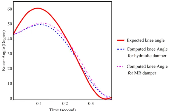
parameters are given in Table 2 and hence the computed knee angle and expected knee angle are also shown in Fig. 6. The simulation results are also summarized in Table 3. The velocities of the shank for both dampers are small enough to be easily stopped without excessive impact by stoppers such as a rubber bumper. Thus, with optimal control parameters when a certain style of motion for thigh is defined, single axis knee with each damper is able to produce proper swing phase motion of an amputee.
Table 2. Optimal values of control parameters
For MR damper For hydraulic damper
Control parameters Optimal values Control parameters Optimal values
co (Ns/m) 169.845 C (Ns/m) 2.613×10⁻³
fc (N) 2.124 lo(m) 3.452×10⁻⁵
fo(N) –153.120 K (N/m) 816.508
Table 3. Summary of results
Simulation
Maximum knee flexion angle, (degree)
Duration of swing phase, (s)
Shank velocity at 0.3 s,
(rad/s)
Mean square error, (degree)
Normal 60.56 0.344 3.887 -
MR damper 50.631 0.368 3.766 3.790
Fig. 6 Expected angle and computed knee angle for MR and hydraulic dampers
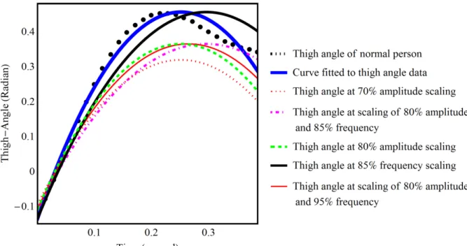
For the purpose of varying the thigh motion from the expected ideal trajectory and to evaluate the performance of the controllers further, a function of periodic type, Eq. (7), is fitted to the input thigh angle data and is varied with different scales of its frequency and amplitude; these curves at acceptable ranges of scaling are shown in Fig. 7. Thus, the dynamic system is solved with the optimal control parameters at different scales of frequency and amplitude independently and both simultaneously. It is found that the MR damper shows an acceptable robustness at 70% or more amplitude scaling and at 85% or more frequency scaling. For hydraulic damper, amplitude scaling of 80% or more and a frequency scaling of 85% or more show an acceptable robustness. When both frequency and amplitude are scaled at a time, MR damper shows an acceptable robustness at 85% or more frequency scaling and at 80% or more amplitude scaling and hydraulic damper shows an acceptable robustness at 95% or more frequency scaling and at 80% or more amplitude scaling. Within the acceptable ranges of scaling, some of the evaluation results and knee angle trajectories are shown in Table 4 and in Fig. 8, respectively.
Function fitted to thigh data:
1 2 sin
3 cos
t t As p p F wts p F wts
, (7)
where As is the amplitude scaling factor, Fsfrequency scaling fac ot r.
Discussion
Fig. 7 Thigh angle of normal person, curve fitted, and deviated thigh angle trajectories
Table 4. Summary of results after using deviated thigh angles
Damper Scaling
Maximum fluxion
angle, (Degree)
Swing phase duration,
(s)
Shank velocity
at 3s, (rad/s)
Mean square
error, (Degree)
Normal without scaling 60.56 0.344 3.887 -
MR damper
70% amplitude scaling 45.660 0.358 2.728 5.181 85% frequency scaling 45.041 0.411 2.794 5.068 80% amplitude scaling and
85% frequency scaling 44.839 0.450 2.341 5.082
Hydraulic damper
80% amplitude scaling 45.685 0.397 2.250 5.577 85% frequency scaling 44.793 0.460 2.377 5.443 80% amplitude and scaling
95% frequency scaling 45.323 0.397 2.262 5.538
Fig. 8 Expected and results of computed knee angles before and after using deviated thigh angles: (a) for MR damper and (b) for hydraulic damper.
Overall, the performance of MR damper and hydraulic damper is evaluated for controlling swing phase of the prosthetic knee taking into account the achievable maximum knee flexion angle, swing phase duration, mean knee angle error, and shank velocity at the end of swing phase. Moreover, as far as the values of control parameters are concerned, they are optimally designed and verified through simulation only, but it can also be verified through experiment. Practically, in order to identify the behaviors of dampers, identification experiments are commonly undertaken to designate values of parameters for parametric models [19]. Hence, the values of the control parameters can also be used as a benchmark to characterize these kinds of dampers for controlling swing phase of prosthetic knee.
(a)
Conclusions
This paper presents designs of hydraulic and MR dampers to control the swing phase of a single axis knee and evaluate their performances. This work can be extended by comparing the performance of the dampers for controlling stance phase of the prosthetic knee. The cost and complexity of damper design can also be included. The designed controlling parameters of the damper can be checked with the thigh motion data while walking on rough terrain, step climbing, jumping, etc. The developed methodology can be adopted for a four bar polycentric knee. The designed control parameters of the dampers may also be utilized in the control strategy of microcontroller based prosthetic knees. Future work by the authors includes the development of specific dampers for prosthetic knees based on the design methodology presented.
References
1. Berger N. (1992). Analysis of Amputee Gait, Chapter 14, In: Atlas of Limb Prosthetics: Surgical, Prosthetic, and Rehabilitation Principles, Bowker J. H. (Ed.), St. Louis: Mosby-Year Book.
2. Chen J. Z., W. H. Liao (2009). Design and Testing of Assistive Knee Brace with Magnetorheological Actuator, Proceedings of IEEE International Conference on Robotics and Biomimetics, Bangkok, Thailand, 512-517.
3. Chen J. Z., W. H. Liao (2010). Design, Testing and Control of a Magnetorheological Actuator for Assistive Knee Braces, Journal of Smart Materials and Structures, 19(3), http://dx.doi.org/10.1088/0964-1726/19/3/035029.
4. Dabiri Y., S. Najarian, M. H. Honarvar (2009). Passive Controller Design for Swing Phase of a Single Axis Above‐knee Prosthesis, Iranian Journal of War and Public Health, 1(3), 76-87.
5. Dabiri Y., S. Najarian, M. R. Eslami, S. Zahedi, H. Farahpour, R. Moradihaghighat (2010). Comparison of Passive and Active Prosthetic Knee Joint Kinematics during Swing Phase of Gait, Proceedings of the 17th Iranian Conference of Biomedical Engineering, Isfahan, Iran, 349-351.
6. Datta D., B. Heller, J. Howitt (2005). A Comparative Evaluation of Oxygen Consumption and Gait Pattern in Amputees Using Intelligent Prostheses and Conventionally Damped Knee Swing-phase Control, Journal of Clinical rehabilitation, 19(4), 398-403.
7. Datta D., J. Howitt (1998). Conventional versus Microchip Controlled Pneumatic Swing Phase Control for Trans-femoral Amputees: User’s Verdict, Prosthetics and Orthotics International, 22(2), 129-135.
8. Dundass C., G. Z. Yao, C. K. Mechefske (2003). Initial Biomechanical Analysis and Modeling of Transfemoral Amputee Gait, Journal of Prosthetics and Orthotics, 15(1), 20-26.
9. Furse A., W. Cleghorn, J. Andrysek (2011). Development of a Low-technology Prosthetic Swing-phase Mechanism, Journal of Medical and Biological Engineering, 31(2), 145-150. 10. Guo H. T., W. H. Liao (2009). Magnetorheological Fluids Based Multifunctional Actuator for Assistive Knee Braces, Proceedings of IEEE International Conference on Robotics and Biomimetics, Guilin, China, 1883-1888.
11. Herr H., A. Wilkenfeld (2003). User-adaptive Control of a Magnetorheological Prosthetic Knee, Industrial Robot: An International Journal, 30(1), 42-55.
12. ICRC Physical Rehabilitation Program (2006). Manufacturing Guidelines: Trans-femoral Prosthesis, International Committee of the Red Cross.
14. Kaufman K. R., J. A. Levine, R. H. Brey, B. K. Iverson, S. K. McCrady, D. J. Padgett, M. J. Joyner (2007). Gait and Balance of Transfemoral Amputees Using Passive Mechanical and Microprocessor-controlled Prosthetic Knees, Gait and Posture, 26(4), 489-493.
15. Kim J. H., J. H. Oh (2001). Development of an Above-knee Prosthesis Using MR Damper and Leg Simulator, Proceedings of IEEE International Conference on Robotics and Automation, Seoul, Korea, 3686-3691.
16. Nandi G. C., A. J. Ijspeert, P. Chakraborty, A. Nandi (2009). Development of Adaptive Modular Active Leg (AMAL) Using Bipedal Robotics Technology, Journal of Robotics and Autonomous Systems, 57(6-7), 603-616.
17. Radcliffe C. W. (1977). The Knud Jansen Lecture: Above-knee Prosthetics, Prosthetics and Orthotics International, 1(3), 146-160.
18. Rispin K., C. Husk, S. Lew, T. Schufeldt, R. Gonzalez (2010). Functional Comparison of the Legs M1 Knee to Commonly Available Developing World Alternatives, ISPO 2010 Congress, Leipzig, Germany.
19. Sapinski B. (2002). Parametric Identification of MR Linear Automotive Size Damper, Journal of Theoretical and Applied Mechanics, 40(3), 703-722.
20. Shabana A. A. (2010). Computational Dynamics (3rd ed.), Wiley.
21. Spencer B. F., S. J. Dyke, M. K. Sain, J. D. Carlson (1997). Phenomenological Model for Magnetorheological Dampers, Journal of Engineering Mechanics, 123(3), 230-238. 22. Suzuki Y. (2010). Dynamic Optimization of Transfemoral Prosthesis during Swing Phase
with Residual Limb Model, Prosthetics and Orthotics International, 34(4), 428-438. 23. Szychowski A., J. Sadler, E. Thorsell, L. A. Roberts (2012). The Jaipur-knee Project:
Getting the Need Right, Global Health Innovation Insight Series.
24. Tahani M., G. Karimi (2010). A New Controlling Parameter in Design of Above Knee Prosthesis, International Scholarly and Scientific Research & Innovation, 4(10), 799-806. 25. Torki A. A., M. F. Taher, A. S. Ahmed (2008). Design and Implementation of a Swing
Phase Control System for a Prosthetic Knee, Proceedings of the IEEE International Conference on Biomedical Engineering, Cairo, Egypt, 1-4.
26. Unal R., R. Carloni, E. E. G. Hekman, S. Stramigioli, H. F. J. M. Koopman (2010). Biomechanical Conceptual Design of a Passive Transfemoral Prosthesis, Proceedings of 32nd Annual International Conference of the IEEE EMBS, Buenos Aires, Argentina, 515-518.
27. Winter D. A (2005). The Biomechanics and Motor Control of Human Gait: Normal, Elderly and Pathological (4th Ed.), Wiley.
28. Xie H. L., Z. Z. Liang, F. Li, L. X. Guo (2010). The Knee Joint Design and Control of Above-knee Intelligent Bionic Leg Based on Magneto-Rheological Damper, International Journal of Automation and Computing, 7(3), 277-282.
29. Xie H., G. Kang, F. Li (2013). The Design and Control Simulation of Trans-femoral Prosthesis Based on Virtual Prototype, International Journal of Hybrid Information Technology, 6(6), 91-100.
30. Xie H., S. Wang, F. Li (2014). Knee Joint Optimization Design of Intelligent Bionic Leg Based on Genetic Algorithm, International Journal Bioautomation, 18(3), 195-206.
Solomon Seid, M.Tech., Ph.D. Student E-mail: [email protected]
Solomon Seid received his B.Tech. in Mechanical Engineering from Defence University College, Ethiopia in 2007. He obtained an M.Tech. in Modelling and Simulation from Defence Institute of Advanced Technology, Pune, India in 2010. Currently he is a Ph.D. student in Indian Institute of Technology Madras, Chennai, India. His current research interests include biomechanics, multibody dynamics, and mechanical design.
Assoc. Prof. S. Sujatha, Ph.D. E-mail: [email protected]
Prof. Sujatha Chandramohan, Ph.D. E-mail: [email protected]
Prof. Sujatha Chandramohan received her Ph.D. degree from Indian Institute of Technology Madras, India in 1991 and at present is a Professor in the Department of Mechanical Engineering in the same
Institute. She has more than 35 years’ experience in teaching,
research and industrial consultancy in the areas of machine dynamics, vehicular vibration, acoustics, condition monitoring and signal analysis. She has authored a book “Vibration and Acoustics:
Measurement and Signal analysis”. She has around 135 publications
![Fig. 4 Input experimental data from [27]](https://thumb-eu.123doks.com/thumbv2/123dok_br/18351618.353099/7.892.125.757.104.839/fig-input-experimental-data-from.webp)