Resonance characteristics of two-span continuous beam under
moving high speed trains
Abstract
The resonance characteristics of a two-span continuous beam traversed by moving high speed trains at a constant velocity is investigated, in which the continuous beam has uniform span length. Each span of the continuous beam is modeled as a Bernoulli-Euler beam and the moving trains are rep-resented as a series of two degrees-of-freedom mass-spring-damper systems at the axle locations. A method of modal analysis is proposed in this paper to investigate the vibration of two-span continuous beam. The effects of different influ-encing parameters, such as the velocities of moving trains, the damping ratios and the span lengths of the beam, on the dynamic response of the continuous beam are examined. The two-span continuous beam has two critical velocities caus-ing two resonance responses, which is different from simple supported beam. The resonance condition of the two-span continuous beam is put forward which depends on the first and second natural frequency of the beam and the moving velocity.
Keywords
critical velocity, moving trains, two-span continuous beam, resonance
Yingjie Wanga,b,∗, QingChao
Weia, Jin Shia and Xuyou
Longa,c
a
School of Civil Engineering, Beijing Jiaotong University, Beijing 100044 – China
b
Department of Construction Engineering, Na-tional Taiwan University of Science and Tech-nology, Taipei 10607 – Chinese Taiwan c
The Third Railway Survey and Design In-stitute Group Corporation, Tianjin 300142 – China
Received 25 Dec 2009; In revised form 2 Mar 2010
∗Author email: [email protected]
1 INTRODUCTION
With the development of high speed railway, the railway induced vibration has long been an interesting topic in the field of civil engineering, such as railway bridge vibrations. This has a huge amount of researches on the dynamic behaviors of railway bridges under the passage of the high speed trains [3–6, 8, 13–17]. Especially a comprehensive study in this topic can be found in references [4, 13, 16]. It is well known that the resonant vibrations occur when the loading frequencies of the moving trains coincide with the natural frequencies of the bridges.
investigated the resonance mechanism and conditions of a train-bridge system using theoretical derivations, numerical simulations, and experimental data analyses [14]. Li and Su researched the resonant vibration for a simply supported girder bridge under high-speed trains, using an idealized vehicle model with a rigid body and four wheelsets [8]. Ju and Lin established a three dimensional finite element model to investigate the resonant characteristics of the simply supported bridges with high piers under high-speed trains [5]. But all of the above researches were based on the simple supported beam. For continuous bridges, Cheung et al. investigated the dynamic response of multi-span non-uniform bridges under moving vehicles and trains with the modified beam vibration functions [3]. Kwark et al. studied dynamic responses of two-span continuous concrete bridges under the Korean high-speed train (KHST) with exper-imental and theoretical methods [6]. Yau researched the effect of the number of spans on the impact response of the continuous beams with finite element method [17]. Based on these investigations, many useful results have been brought out. Unfortunately, no further details were proposed for the resonance characteristics, especially for the two-span continuous beam. Because of the continuous action of moving trains, the certain frequencies of excitation will be imposed on the two-span continuous beam to result in beam resonance. In the present study, the dynamic response of two-span continuous beam under moving high speed trains were investigated with modal superposition method and the reasons for beam resonance were revealed also. Taking the max displacement and the dynamic impact factor of the midpoint of the beam as indices, several parameters such as moving trains velocities, damping ratios and span lengths of the beam, are chosen to investigate the effect of moving trains on the dynamic responses of the beam. Different from simple supported beam, the two-span continuous beam has two critical velocities causing two resonance responses, which depends on the first and second natural frequency of the beam and the moving velocity. From resonance view, the results are useful for suppressing the vibration of the two-span continuous beam under moving high speed trains.
2 FORMULATION
2.1 Basic considerations
two-span continuous beam subjected to moving trains as in Figure 1:
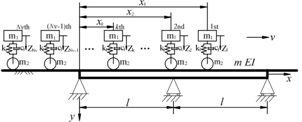
1. The moving trains are modeled as a series of two degrees-of-freedom mass-spring-damper systems at the axle locations, and each mass-spring-damper system consists of a sprung mass and an unsprung mass interconnected by a spring and a dashpot.
2. The two-span continuous beam is modeled as an elastic Bernoulli-Euler beam with uni-form span length.
3. The high speed trains travel at a constant speed v. And for the initial conditions, the
first mass-spring-damper system is located at the left-hand end of the continuous beam.
Figure 1 Two-span continuous beam under moving trains.
2.2 Vehicle
As shown in Figure 1, it is assumed that there are Nv moving mass-spring-damper systems
in direct contact with the beam. For the typicalkth moving mass-spring-damper system, the
sprung mass m1 and the unsprung mass m2 are interconnected by a spring of stiffness k1
and a dashpot of damping coefficient c1. The motion of unsprung mass is constrained by the
displacement of the beam, so its vertical displacement is also the beam vertical displacement
where the kth system is located. When the kth mass-spring-damper system runs on the
two-span continuous beam, the motion equation of the sprung massm1can be written as
m1Z¨k(t)+c1[Z˙k(t)−y˙(xk, t)]+k1[Zk(t)−y(xk, t)]=0 (1)
where m1 is the mass of sprung mass, Zk and y(xk, t) are vertical displacements of sprung
mass and unsprung mass, dots represent differentiation with respect to time t.
2.3 Two-span continuous beam
As shown in Figure 1, a two-span continuous beam with each span length l subjected to
mass-spring-damper system from the left-hand end of the continuous beam isxk. Then the motion
equation for moving trains on the two-span continuous beam can be written as
EIy′′′′(x, t)+my¨(x, t)+cy˙(x, t)=F(x, t) (2)
where m is the constant mass per unit length, EI is the bending stiffness, c the damping of
the beam, y(x,t) the displacement of the beam, and dots and primes represent differentiation
with respect to timet and coordinate x.
F(x, t)=
Nv ∑
k=1
{(m1+m2)g−m2y¨(xk, t)+c1[Z˙k(t)−y˙(xk, t)]+k1[Zk(t)−y(xk, t)]}
⋅δ(x−xk)⋅[H(t−tk)−H(t−tk−∆t)]
(3)
Here, tk the arriving time of the kth mass-spring-damper system at the beam, tk=xk/v.
∆t the time of the load passing the beam, ∆t=2l/v,H(⋅) is a unit step function, and δ(⋅) is the Dirac delta function.
Based on the modal superposition method, the solution of Eq. (2) can be expressed as
y(x, t)=
∞
∑
n=1
qn(t)φn(x) (n=1,2⋯∞) (4)
where qn(t) is the nth modal amplitude and φn(x) is the nth mode shape function of the
beam.
Substituting Eq. (4) and Eq. (3) into Eq. (2), and multiplying by φn and integrating the
resultant equation with respect to x between 0 and 2l; and then applying the orthogonality
conditions, the equation of motion in terms of the modal displacementqn(t)is given as:
¨
qn(t)+2ξnωnq˙n(t)+ω
2
nqn(t)=
Fn(t)
Mn
(5)
whereωn,ξn,Fn(t) andMnare the modal frequency, the damping ratio, the generalized force
and the modal mass of the nth mode, respectively, and
Fn(t)= Nv ∑
k=1
{(m1+m2)gφn(xk)−m2 ∞
∑
i=1
¨
qi(t)φi(xk)φn(xk)+[k1Zk(t)+c1Z˙k(t)]φn(xk)
−
∞
∑
i=1
[k1qi(t)+c1q˙i(t)]φi(xk)φn(xk)}⋅[H(t−tk)−H(t−tk−∆t)]
(6)
Mn=∫
2l
0 mφ 2
n(x)dx (7)
¨ qn(t)+
m2
Mn Nv ∑
k=1
∞
∑
i=1
¨
qi(t)ΦinkH˜k+2ξnωnq˙n(t)+
c1
Mn Nv ∑
k=1
∞
∑
i=1
˙
qi(t)ΦinkH˜k
+ω2
nqn(t)+
k1
Mn Nv ∑
k=1
∞
∑
i=1
qi(t)ΦinkH˜k−
k1
Mn Nv ∑
k=1
Zk(t)ΦnkH˜k−
c1
Mn Nv ∑
k=1
˙
Zk(t)ΦnkH˜k
= (m
1+m2)g
Mn
Nv ∑
k=1
ΦnkH˜k
(8)
where Φink=φi(xk)φn(xk), Φnk =φn(xk) and ˜Hk=[H(t−tk)−H(t−tk−∆t)].
Then substituting Eq. (4) into Eq. (1), the motion equation of the sprung mass m1 can
be written as
m1Z¨k(t)+c1Z˙k(t)+k1Zk(t)−
∞
∑
i=1
[c1q˙i(t)+k1qi(t)]φi(xk)=0 (9)
2.4 Natural frequency and mode shape functions
The mode shape of the two-span continuous beam can be divided into two groups, which are symmetrical and asymmetrical, respectively [12]. The circular frequency can be identified as
ωi=λ
2 i √ EI m = ⎧⎪⎪⎪ ⎨⎪⎪⎪ ⎩
(i+1 2l π)
2√
EI
m i=1, 3, 5, 7,⋯
(0.25+i/2
l π)
2√
EI
m i =2, 4, 6, 8,⋯
(10)
When i=1,3,5. . . and x∈[0,2l], the mode shape is expressed as
φi(x)=sin(λix) (11)
When i=2,4,6. . . andx∈[0, l],
φi(x)=sin(λix)
sin(λil)
−sinh(λix) sinh(λil)
(12)
When i=2,4,6. . . and x∈[l,2l],
φi(x)=cos(λix−λil)−cosh(λix−λil)−[sin(λix−λil)−sinh(λix−λil)]⋅cot(λil) (13)
3 SOLUTION
After obtaining the natural frequencies and mode shape functions of the two-span continuous
beam, suppose thatNbmodes are used in this paper. Combining Eq. (8) and (9), the equations
MU¨+CU˙ +KU =F (14)
whereM,C,K are the mass, damping and stiffness matrices; ¨U, ˙U,U the vectors of
accelera-tions, velocities and displacement respectively; and F the vector of external forces. SoU and
F are the (Nb+Nv)×1 dimensional vectors,
U =[ q1 q2 ⋯ qNb Z1 Z2 ⋯ ZNv ]
′
(15a)
F =[ ρ1ψ1 ρ2ψ2 ⋯ ρNbψNb 0 0 ⋯ 0 ]
′
(15b)
where ρn= (
m1+m2)g
Mn and ψn=
Nv ∑
k=1
ΦnkH˜k.
Especially, M,C,K can be assembled with four matrices.
M =[ Mbb Mbv Mvb Mvv ]
, (16a)
C=[ Cbb Cbv Cvb Cvv ]
, and (16b)
K=[ KKbb Kbv
vb Kvv ]
. (16c)
For mass matrix M,
Mbb=
⎡⎢ ⎢⎢ ⎢⎢ ⎢⎢ ⎣
1+∆1Θ11 ∆1Θ21 ⋯ ∆1ΘN
b1
∆2Θ12 1+∆2Θ22 ⋯ ∆2ΘNb2
⋯ ⋯ ⋱ ⋯
∆NbΘ1Nb ∆NbΘ2Nb ⋯ 1+∆NbΘNbNb
⎤⎥ ⎥⎥ ⎥⎥ ⎥⎥ ⎦Nb×Nb
, (17a)
Mvv=
⎡⎢ ⎢⎢ ⎢⎢ ⎢⎢ ⎣
m1
m1
⋱ m1
⎤⎥ ⎥⎥ ⎥⎥ ⎥⎥ ⎦Nv×Nv
, (17b)
Mbv =0, (17c)
Mvb=0. (17d)
For damping matrix C,
Cbb=
⎡⎢ ⎢⎢ ⎢⎢ ⎢⎢ ⎣
2ξ1ω1+Γ1Θ11 Γ1Θ21 ⋯ Γ1ΘNb1
Γ2Θ12 2ξ2ω2+Γ2Θ22 ⋯ Γ2ΘNb2
⋯ ⋯ ⋱ ⋯
ΓNbΘ1Nb ΓNbΘ2Nb ⋯ 2ξNbωNb+ΓNbΘNbNb
⎤⎥ ⎥⎥ ⎥⎥ ⎥⎥ ⎦Nb×Nb
Cvv= ⎡⎢ ⎢⎢ ⎢⎢ ⎢⎢ ⎣ c1 c1 ⋱ c1 ⎤⎥ ⎥⎥ ⎥⎥ ⎥⎥ ⎦Nv×Nv
, (18b)
Cbv =
⎡⎢ ⎢⎢ ⎢⎢ ⎢⎢ ⎣
−Γ1Ψ11 −Γ1Ψ12 ⋯ −Γ1Ψ1N
v
−Γ2Ψ21 −Γ2Ψ22 ⋯ −Γ2Ψ2N
v
⋯ ⋯ ⋱ ⋯
−ΓN
bΨNb1 −ΓNbΨNb2 ⋯ −ΓNbΨNbNv
⎤⎥ ⎥⎥ ⎥⎥ ⎥⎥ ⎦Nb×Nv
, (18c)
Cvb=
⎡⎢ ⎢⎢ ⎢⎢ ⎢⎢ ⎣
−c1Φ11 −c1Φ21 ⋯ −c1ΦNb1
−c1Φ12 −c1Φ22 ⋯ −c1ΦN
b2
⋯ ⋯ ⋱ ⋯
−c1Φ1N
v −c1Φ2Nv ⋯ −c1ΦNbNv
⎤⎥ ⎥⎥ ⎥⎥ ⎥⎥ ⎦Nv×Nb
. (18d)
For stiffness matrix K,
Kbb=
⎡⎢ ⎢⎢ ⎢⎢ ⎢⎢ ⎣
ω21+Λ1Θ11 Λ1Θ21 ⋯ Λ1ΘNb1
Λ2Θ12 ω
2
2+Λ2Θ22 ⋯ Λ2ΘNb2
⋯ ⋯ ⋱ ⋯
ΛNbΘ1Nb ΛNbΘ2Nb ⋯ ω
2
Nb
+ΛN
bΘNbNb
⎤⎥ ⎥⎥ ⎥⎥ ⎥⎥ ⎦Nb×Nb
, (19a)
Kvv=
⎡⎢ ⎢⎢ ⎢⎢ ⎢⎢ ⎣ k1 k1 ⋱ k1 ⎤⎥ ⎥⎥ ⎥⎥ ⎥⎥ ⎦Nv×Nv
, (19b)
Kbv=
⎡⎢ ⎢⎢ ⎢⎢ ⎢⎢ ⎣
−Λ1Ψ11 −Λ1Ψ12 ⋯ −Λ1Ψ1Nv
−Λ2Ψ21 −Λ2Ψ22 ⋯ −Λ2Ψ2N
v
⋯ ⋯ ⋱ ⋯
−ΛN
bΨNb1 −ΛNbΨNb2 ⋯ −ΛNbΨNbNv
⎤⎥ ⎥⎥ ⎥⎥ ⎥⎥ ⎦Nb×Nv
, (19c)
Kvb=
⎡⎢ ⎢⎢ ⎢⎢ ⎢⎢ ⎣
−k1Φ11 −k1Φ21 ⋯ −k1ΦN
b1
−k1Φ12 −k1Φ22 ⋯ −k1ΦN
b2
⋯ ⋯ ⋱ ⋯
−k1Φ1Nv −k1Φ2Nv ⋯ −k1ΦNbNv
⎤⎥ ⎥⎥ ⎥⎥ ⎥⎥ ⎦Nv×Nb
. (19d)
where ∆n= Mm2n, Γn=Mc1n, Λn= Mk1n, Θin= Nv
∑
k=1
ΦinkH˜k, Ψnk=ΦnkH˜k.
To obtain simultaneously the dynamic responses of the two-span continuous beam, the equations of motion as given in Eq. (14) will be solved in a step-by-step integration method
using the Newmark-βmethod [11, 13]. The integration scheme of Newmark-β method consists
of the following equations:
{U¨}
{U˙}
t+∆t={U˙}t+a6{U¨}t+a7{U¨}t+∆t (21)
where the coefficients are
α0=
1
β∆t2, α1=
γ
β∆t, α2= 1
β∆t, α3= 1
2β −1,
α4=
γ
β −1, α5= ∆t
2 (
γ
β −2), α6=∆t(1−γ), α7=γ∆t. (22)
In this study, β=1/4 and γ=1/2 are selected, which implies a constant acceleration with
unconditional numerical stability.
4 NUMERICAL INVESTIGATION
(a) CRH high speed train
(b) Axle arrangements of CRH high speed train model
Figure 2 CRH high speed train and axle arrangements.
Consider a two-span continuous beam with l=20m, EI=2.5×10¹⁰ Nm2, m=3.4088×10⁴
kg/m, ξ=0.025. CRH (China Railway High-speed) high speed train consisting of eight cars,
as shown in Figure 2(a), is used as the external moving trains acting on the beam. Figure 2(b) shows the axle arrangements of CRH high speed train model, with the full length of
each cardv=25m, the rated distance between the two bogies of a cardc=17.5m, and the fixed
distance between the two wheel-axles of a bogiedw=2.5m. Each wheel assembly is modelled as
an equivalent 2DOF system with a sprung massm1=9500kg, an unsprung mass m2=3300kg,
a spring with stiffness k1=2.5×10 5
N/m and a dashpot with damping coefficient c1=4.5×10
4
Table 1 Properties of the two-span continuous beam.
l(m) EI(Nm2) m(kg/m) ξ ω1 (rad/s) ω2(rad/s)
20 2.5×10¹⁰ 3.4088×10⁴ 0.025 21.13 33.02
Table 2 Properties of the moving CRH high speed train model.
Nv dv(m) dc(m) dw(m) m1(kg) m2(kg) k1(N/m) c1(Ns/m)
4×8 25 17.5 2.5 9500 3300 2.5×10⁵ 4.5×10⁴
Figure 1 shows a two-span continuous beam with each span length l subjected to a series
of mass-spring-damper systems at constant speed v and Figure 2 shows the moving CRH
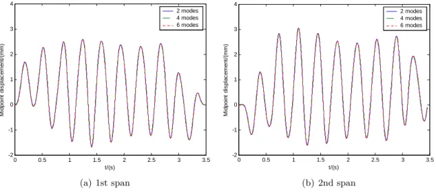
high speed train model. To compute the dynamic response of the two-span continuous beam under moving trains, the number of modes of the beam should be considered first. In order to verify that a sufficient number of modes has been used in the analysis, we first compute the displacement response at the midpoint of each span of the two-span continuous beam under the CRH high speed train at 250km/h using either 2, 4, or 6 modes. From the convergent verification of computed results in Figure 3, the first 6 modes are sufficient to compute the displacement response of the two-span continuous beam under moving trains. For this reason, the same number of modes will be considered in the following examples.
0 0.5 1 1.5 2 2.5 3 3.5
-2 -1 0 1 2 3 4
t/(s)
M
id
p
o
in
t
d
is
p
la
c
e
m
e
n
t/
(m
m
)
2 modes 4 modes 6 modes
(a) 1st span
0 0.5 1 1.5 2 2.5 3 3.5
-2 -1 0 1 2 3 4
t/(s)
M
id
p
o
in
t
d
is
p
la
c
e
m
e
n
t/
(m
m
)
2 modes 4 modes 6 modes
(b) 2nd span
Figure 3 Test of convergence.
4.1 Effect of moving trains velocities
To compare the resonance characteristics of simple supported beam with the two-span
m=3.4088×10⁴kg/m,ξ=0.025. Then the displacement responses of the two beams under mov-ing CRH high speed trains were computed. For different movmov-ing trains velocities from 5km/h to 600km/h, the max displacement solved for the midpoint of each span of the continuous beam and the simple supported beam has been plotted against the moving trains velocities in Figure 4.
0 100 200 300 400 500 600
0 2 4 6 8 10 12 14
Velocity/(km/h)
M
a
x
d
is
p
la
c
e
m
e
n
t/
(m
m
)
1st span 2nd span simple beam
Figure 4 Max displacement for the midpoint of the two beams vs moving trains velocities.
As one can see, for the two-span continuous beam, there exist two resonant peaks for the max displacement response curves of the 1st and 2nd span of the continuous beam. As shown in Figure 4, the two critical velocities of the two-span continuous beam are about 300km/h and 465km/h respectively. To illustrate the resonant phenomena of the two-span continuous beam subjected to the trains traveling at velocities of 300km/h and 465km/h, the time history responses of the midpoint displacement of the beam have been plotted in Figure 5. Both the displacement responses of the 1st and 2nd span are built up continuously as there are more moving loads passing through the beam. This is so called resonance phenomenon for train-induced response of railway bridges [15].
As one can see, for simple-supported beam, there exists only one resonant peak for the max displacement response curves. As shown in Figure 4, the critical velocity of the simple supported beam is about 300km/h. So when the moving high speed trains is certain, the first critical velocity of the two-span continuous beam is the same with the simple supported beam. But at that resonance condition the max displacement of the simple supported beam is much larger than the two-span continuous beam.
0 1 2 3 4 5 6 7 8 9 10 -8 -6 -4 -2 0 2 4 6 8 10 vt/l M id p o in t d is p la c e m e n t/ (m m ) v=300km/h v=465km/h
(a) 1st span
0 1 2 3 4 5 6 7 8 9 10
-8 -6 -4 -2 0 2 4 6 8 10 vt/l M id p o in t d is p la c e m e n t/ (m m ) v=300km/h v=465km/h
(b) 2nd span
Figure 5 Resonant response of midpoint displacement of 1st and 2nd span.
only the dynamic response of the second span will be considered in the subsequent research. Resonance is produced by the periodic repetition of moving high speed trains circulating along the bridge. It can be deduced from Figure 2 that the most important characteristic length related to the appearance of resonance must be the length of the vehicle, which has been validated by Museros P. [9]. For moving trains traveling on the beam, the resonant condition of the beam can be derived as follows [13, 14]:
vbrn =3.6
⋅fbn⋅d
i ,(n=1,2,3
⋯;i=1,2,3,⋯) (23)
where vbrn is the resonant moving trains velocity (km/h); fbn is the nth natural frequency of
the beam (Hz); d is the characteristic length of the moving high speed trains (m);i represents
the number of complete oscillation cycles for thenth mode of the beam to vibrate during the
passage of two adjacent loads [10, 19].
For the two-span continuous beam, the exact natural frequencies corresponding to the first and second modes are 21.13rad/s and 33.02rad/s respectively listed in Table 1, and the characteristic length is taken as the load interval which is approximately 25m. So the first and second resonant moving trains speeds for resonant conditions estimated by Eq. (23) are
vbr1=
3.6⋅fb1⋅d
i =
3.6×21.13×25
1×2×π =302.67km/h
vbr2=
3.6⋅fb2⋅d
i =
3.6×33.02×25
1×2×π =472.98km/h
vbr1=
3.6⋅fb1⋅d
i =
3.6×21.13×25
1×2×π =302.67km/h
The resonant moving loads speeds estimated by Eq. (23) are in good accordance with the critical moving loads speeds from the simulated results, as shown in Figure 4. So for the simple supported beam it is evident that the resonant peak is mainly due to coincidence of the excitation frequencies implied by the moving trains at different speeds with the first frequency of the beam. But for the two-span continuous beam, the two resonant peaks are mainly with the first and second frequencies of the beam.
4.2 Effect of damping ratios
Theoretically, the structural damping is difficult to determine. Generally, the range of damping ratios is between 0.01 and 0.06. The damping ratio of the two-span continuous beam has been chosen as 0.01, 0.02, 0.04 and 0.06 to study the effect of damping on the dynamic response of the beam. The moving trains velocity is also from 5km/h to 600km/h, the max displacement solved for the midpoint of the beam has been plotted against the moving trains velocities in Figure 6.
0 100 200 300 400 500 600
0 2 4 6 8 10 12
Velocity/(km/h)
M
a
x
d
is
p
la
c
e
m
e
n
t/
(m
m
)
ξ=0.01
ξ=0.02
ξ=0.04
ξ=0.06
Figure 6 Max displacement of the beam with different damping ratios vs moving trains velocities.
As shown in Figure 6, it is proved that the damping ratio of the two-span continuous beam has little impact on the maximum deflection of the midpoint of the beam when moving trains travel except at the critical velocities. But in resonance condition, the damping of the beam can suppress the vibration of the beam obviously, and with the increase of the damping
ratio the max deflection of the beam decreases rapidly. When the damping ratio ξ is 0.01,
of the continuous beam, and it only affects the max deflection of the beam. Taking into the effect of the damping ratios on the continuous beam resonance is little, in the following research
the damping ratioξ=0.025 is still used.
4.3 Effect of span length
In order to study the effect of different span length on the dynamic responses of the two-span continuous beam, the dynamic impact factor of the midpoint of the beam is taken as index. The dynamic impact factor for the displacement of the two-span continuous beam subjected to the moving trains is defined as [15]
I= yd(x)−ys(x) ys(x)
(24)
where yd(x) and ys(x) denote the max dynamic and static displacement of the two-span
con-tinuous beam at positionx due to the action of moving trains respectively. In this paper, when
the high speed trains move at a much lower velocity, such as 0.36km/h, then the displacement of the beam was taken as the static displacement.
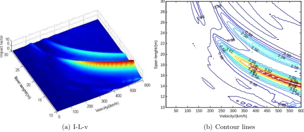
As we all know, with different span lengths, the section stiffness and the unit-length mass should be changed. But in this paper, to study the effect of span length to the resonance conditions in theoretically only, the other parameter values of the beam are supposed to be the same with section 4.1. The span length of the continuous beam is chosen from 10m to 30m and the moving trains velocity is from 5km/h to 600km/h also. The dynamic impact factor solved for the midpoint of the beam has been plotted against the span lengths and the velocities in Figure 7(a), with its contour lines given in Figure 7(b).
(a) I-L-v
50 100 150 200 250 300 350 400 450 500 550 600 10
12 14 16 18 20 22 24 26 28 30
Velocity/(km/h)
S
p
a
n
l
e
n
g
h
t/
(m
)
0.98
0.98
0.98
0 .98
0.98 0.98
0.98
0.98 2.56 2.56
2.56
2.56 2.56
2.56
2.56
2.56
2.56
3.62 3.62
3.62
3.62 5.22
5.22 5.22
5.226.78
6.7 8
6.78
(b) Contour lines
Figure 7 Effects of span lengths and velocities on the dynamic impact factor of the midpoint of the beam.
bands of the two-span continuous beam moves shift to higher moving trains velocities areas, and at the same time the vibration intensified strongly. When the span length is certain, there are two critical velocities, under which the dynamic impact factor of the beam is large, and the resonance occurred. So to suppress the vibration of the two-span continuous beam under moving high speed trains, the two resonances should be considered together.
5 CONCLUSIONS
In this paper according to the vibration differential equation of two-span continuous beam under moving trains, the resonance characteristics of the beam is investigated. Then the influences of moving load velocities, damping ratios and span lengths of the beam to the vibration of the two-span continuous beam were studied in detail. On the base of the study, the following conclusions can be drawn:
1. The two-span continuous beam has two critical velocities causing the resonance response, which is different from simple supported beam. These two resonances are mainly due to the coincidence of the excitation frequencies implied by the moving trains at different speeds with the first and second natural frequency of the continuous beam.
2. The damping ratios of the two-span continuous beam has great impact on the maximum deflection merely on the conditions of moving trains at the critical velocity, otherwise, it has little effect on suppressing the vibration of the beam. On the resonance condition, the bigger damping ratios lead to the smaller deflection.
3. The two-span continuous beam has two resonance bands. So to control the vibration of the two-span continuous beam, the two resonance should be considered together. From resonance view, the results are useful for suppressing the vibration of the two-span continuous beam under moving high speed trains.
Acknowledgment The author would like to thank Prof. Jenn-Shin Hwang of National Tai-wan University of Science and Technology (NTUST) for the convenient studying environ-ment when he statyed in NTUST. The research reported herein is supported by Natural Sci-ence Foundation of China (50578010, 50978024), National Postdoctoral Foundation of China (20090450289) and Doctoral Disciplinary Special Research Project of Chinese Ministry of Ed-ucation (20090009120020)
References
[1] Y.S. Cheng, F.T.K. Au, and Y.K. Cheung. Vibration of railway bridges under a moving train by using bridge-track-vehicle element.Engineering Structures, 23(5):1597–1606, 2001.
[2] Y.S. Cheng, F.T.K. Au, Y.K. Cheung, and D.Y. Zheng. On the separation between moving vehicles and bridge.
[3] Y. K. Cheung, F. T. K. Au, D. Y. Zheng, and Y.S. Cheng. Vibration of multi-span non-uniform bridges under moving vehicles and trains by using modified beam vibration functions. Journal of Sound and Vibration, 228(3):611–628, 1999.
[4] L. Fr´yba.Vibration of solids and structures under moving loads. Thomas Telford Ltd, London, UK, 2 edition, 1999.
[5] S.H. Ju and H.T. Lin. Resonance characteristics of high-speed trains passing simply supported bridges. Journal of Sound and Vibration, 267(5):1127–1141, 2003.
[6] J.W. Kwark, E.S. Choi, Y.J. Kim, B.S. Kim, and S.I. Kim. Dynamic behavior of two-span continuous concrete bridges under moving high-speed train.Computers and Structures, 82(4-5):463–474, 2004.
[7] U. Lee. Revisiting the moving mass problem: onset of separation between the mass and beam. Journal of Vibration and Acoustics, 118(3):517–521, 1996.
[8] J.Z. Li and M.B. Su. The resonant vibration for a simply supported girder bridge under high-speed trains. Journal of Sound and Vibration, 224(5):897–915, 1999.
[9] P. Museros. Vehicle-bridge interaction and resonance effects in simply supported bridges for high speed lines. PhD thesis, Superior School of Industrial Engineering, Technical Univ. of Madrid, Madrid, Spain, 2002. (in Spanish).
[10] P. Museros and E. Alarc´on. Influence of the second bending mode on the response of high-speed bridges at resonance.
Journal of Structural Engineering, 131(3):404–415, 2005.
[11] N.M. Newmark. A method of computation for structural dynamics.Journal of the Engineering Mechanics, 85(3):67– 94, 1959.
[12] Y.F. Teng, N.G. Teng, and X.J. Kou. Vibration analysis of continuous maglev guideway considering the magnetic levitation system. Journal of Shanghai Jiaotong University (Science), 13(2):211–215, 2008.
[13] H. Xia and N. Zhang.Dynamic Interaction of Vehicle and Structures. Science Press, Beijing, China, 2 edition, 2005. (in Chinese).
[14] H. Xia, N. Zhang, and W.W. Guo. Analysis of resonance mechanism and conditions of train-bridge system.Journal of Sound and Vibration, 297(3-5):810–822, 2006.
[15] Y. B. Yang, J. D. Yau, and L. C. Hsu. Vibration of simple beams due to trains moving at high speeds.Engineering Structures, 19(11):936–944, 1997.
[16] Y. B. Yang, J. D. Yau, and Y. S. Wu.Vehicle-Bridge Interaction Dynamics-with applications to high-speed railways. World Scientific Publishing Company, Singapore, 2004.
[17] J.D. Yau. Resonance of continuous bridges due to high speed trains. Journal of Marine Science and Technology, 9(1):14–20, 2001.
[18] J.D. Yau. Suppression of train-induced vibrations of continuous truss bridges by hybrid tmds. InProc. of the 21st International Congress of Theoretical and Applied Mechanics with CD-ROM, pages 11287–11288, Warsaw, Poland, 2004.
[19] J.D. Yau and Y.B. Yang. Vertical accelerations of simple beams due to successive loads traveling at resonant speeds.
Journal of Sound and Vibration, 289((1-2)):210–228, 2006.
[20] M. Ziyaeifar. Interaction study of train–bridge–track systems using maxwell model. Vehicle System Dynamics, 43(11):771–794, 2005.