• Nenhum resultado encontrado

Development and characterization of ZnO piezoelectric thin film on  polymeric substrates for tendon regeneration

N/A
N/A
Protected

Academic year: 2021

Share "Development and characterization of ZnO piezoelectric thin film on  polymeric substrates for tendon regeneration"

Copied!
93
0
0

Texto

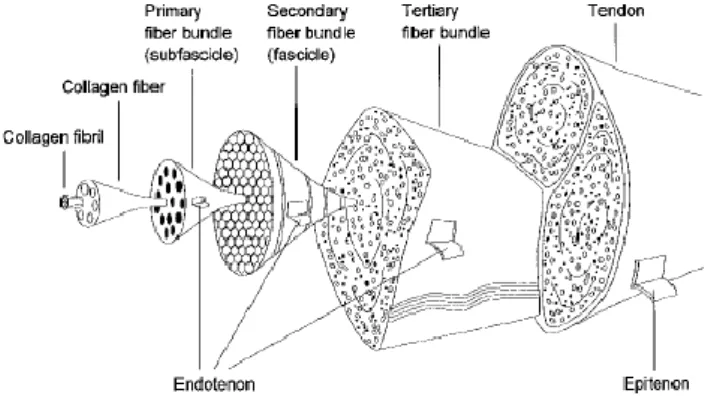
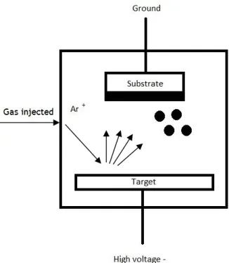
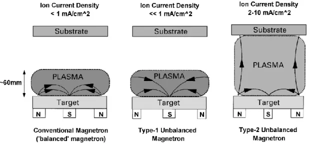
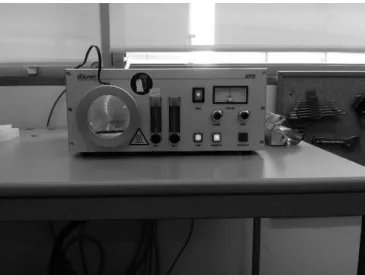
Faculdade de Engenharia da Universidade do Porto. MASTER DISSERTATION. José Rui Azevedo Costa. October 2017. . Faculdade de Engenharia da Universidade do Porto. Development and characterization of ZnO . piezoelectric thin films on polymeric substrates for . tendon regeneration. José Rui Azevedo Costa. Report carried out under the Master in Biomedical Engineering. Supervisor: Prof.ª Doutora Maria Ascensão Ferreira Silva Lopes (FEUP) Co-Supervisor: Doutor Armando José Barros Ferreira (UM). October 2017 . © José Rui Azevedo Costa, 2017. . i. Abstract. Tendon injuries are common in sports and in the workplace. Frequently cause joint pain,. dysfunction, and disability, representing a significant burden to the health-care system. There. are different strategies available for tendon repair, however, these strategies are recognized. to be associated with numerous limitations and drawbacks. Successful repair of tendons using. a tissue engineering approach requires the engineered tissue to possess similar mechanical and. functional characteristics as the native uninjured tendon. Scaffold-based strategies aim at. both mechanically reinforcing and augmenting the tendon repair and biologically enhancing. its intrinsic healing. Novel paradigms for tissue engineering using piezoelectric materials show. strong potential during tissue regeneration.. The main objective of this work, that results from the collaboration between FEUP-DEMM. and CFUM (centre of physics of University of Minho), aims to develop a piezoelectric coating. based on zinc oxide, ZnO, to be applied in a PET based scaffold developed by the group, which. has a good mechanical performance to be used for tendons repair, but lacks bioactivity.. ZnO thin films were coated on PET substrates using direct current (DC) magnetron sput-. tering technique Before the deposition of the thin films, the PET substrates were submitted. to a cleaning protocol with plasma. Structural analysis of the thin film by X-ray diffraction. show a very intense ZnO (0 0 2) diffraction peak (2θ = 34.4º), which indicates the formation. of crystalline ZnO with Wurtzite structure with good growth along the c-axis known by a large. piezoelectric constant. The highest peak was observed for O2 flow of 16.25 sccm, resulting in. the highest piezoelectric coefficient, determined by d33 value of 4.5 ± 0.3 pN/C. Morphology. analyses using scanning electron microscopy show that ZnO particles are bigger and better. defined resulting in a film thickness of 1.8 µm when low O2 flows are used (16 to 16.75 sccm). and denser when gas flow increases (17 and 20 sccm) resulting in a small film thickness of 0.5. µm.. Electrical analyses of the thin films show that with the increase of O2 flux from 16 sccm to. 20 sccm the film resistivity increased from 6.58x10⁻⁴ Ω.cm to 106 Ω.cm and transmittance from. ii. 8.1% to 79.5%. Increases in the O2 flows changes the films behaviour from conductor to insula-. tor. . During adhesion assays, the ZnO coating did not take off and it was classified with 4, in. accordance with the norm D 3359 – 97 standard from ASTM. The deposition process in polyeth-. ylene terephthalate (PET) increases the contact angle from 73º to 104º, turning more hydro-. phobic. The film degradation was tested with PBS (pH 7), resulting in no changes in weight.. However, SEM images from the degradation assays show some uncoated regions that indicate. some film detachment.. Cell cultures studies using fibroblasts were performed for 4, 7 and 10 days in order to. evaluate the surface functionalization of the ZnO thin film. Regarding the cell culture studies,. the low number of cells observed by SEM and confirmed by MTT assay show low increment of. the cell culture not allowing the evaluation of the ZnO thin film in these conditions. . . . . iii. Resumo. As lesões nos tendões são comuns no desporto e no local de trabalho e podem provocar. dores articulares, disfunção e incapacidade. Estas lesões representam um peso significativo. para o sistema de saúde. Existem diferentes tipos de estratégias disponíveis para a reparação. de tendões. No entanto, estas estratégias apresentam inúmeras limitações e desvantagens. A. reparação do tendão para ser bem-sucedida (através da engenharia de tecidos), requer que o. tecido manipulado possua características mecânicas e funcionais semelhantes às do tendão ori-. ginal. As estratégias baseadas em scaffolds visam mimetizar as propriedades mecânicas e a. bioatividade do tendão original. Novos paradigmas na engenharia de tecidos com materiais com. propriedades piezoelétricas apresentam forte potencial na regeneração de tecidos.. O principal objetivo desta dissertação, que resulta da colaboração entre a FEUP-DEMM e o. Departamento de Física-UM, é desenvolver um revestimento piezoelétrico de óxido de zinco,. ZnO, para ser aplicado num scaffold de PET previamente desenvolvido pelo grupo, o qual tem. um bom desempenho mecânico, mas carece na bioatividade.. Filmes finos de ZnO foram depositados sobre substratos de PET através da técnica de pul-. verização catódica de corrente contínua (CC). Todos os substratos de PET foram sujeitos a um. protocolo de limpeza por plasma antes de cada deposição. Estudos de difração de raios-X aos. filmes finos revelam um pico cristalino a (2θ = 34,4º), sugerindo a formação da estrutura Wurt-. zite (0 0 2) com crescimento perpendicular ao substrato (c-axis), relacionado com a piezoele-. tricidade dos filmes finos de ZnO. O pico mais intenso foi observado na condição de 16,25 sccm. de O2, resultando no maior coeficiente piezoelétrico d33 de 4,5 ± 0,3 pN/C. Análises da morfo-. logia através de microscopia eletrônica de varrimento mostram que para fluxos mais baixos de. O2 (16,00-16,75 sccm) o tamanho de grão e porosidade das colunas é maior do que para as. amostras depositadas com maiores fluxos (17,00 e 20,00 sccm). Consequentemente, obteve-se. uma espessura de filme de 1,8 μm, para as amostras com deficiência de O2 e uma espessura de. 0,5 μm para as amostras com excesso de O2.. As análises aos filmes finos mostram que o aumento do fluxo de O2 de 16 sccm para 20. sccm aumenta a resistividade elétrica do filme de 6,58x10⁻⁴ Ω.cm para cerca de 106 Ω.cm e a. transmitância de 8,1% para 79,5%, transformando o filme condutor em isolador. . Durante os ensaios de adesão o revestimento não decolou tendo sido avaliada a adesão com. o nível 4, de acordo com a norma D 3359 - 97 da ASTM. Testes de molhabilidade, ângulo de. contacto, foram avaliados obtendo-se um aumento do ângulo de contato do PET de 73º para. 104º, para o sistema PET mais filme. A fim de avaliar a degradação do filme de ZnO a amostra. com maior valor de piezoeletricidade foi testada com PBS (pH 7). Destes dos ensaios verificou-. se algumas regiões não revestidas com ZnO, indicando pouca adesão do filme quando em con-. tacto com o PBS. . iv. Ensaios de Culturas celulares, usando fibroblastos, foram realizados durante 4, 7 e 10 dias. de forma a avaliar a funcionalidade do filme fino de ZnO. Em relação a estes estudos, o baixo. número de células observadas por SEM e confirmado pelo ensaio de MTT demonstra que os. filmes de ZnO, nestas condições, não promoveram o crescimento celular.. . . v. . vi. Acknowledgments. First, I would like to thank to my professor Maria Ascensão Lopes for the opportunity to. develop this work as well as for all the availability, support, help, patience, motivation and. advice provided during the whole work. . I would like to express my deepest gratitude to my co advisor Dr. Armando for their excel-. lent and constant guidance, generous support and valuable advice, no word would ever be. enough to express you all my gratitude.. With the best thanks to the Nucleus of Physics of the University of Minho of the Campus of. Azurém for the availability of the deposition chamber. Within this nucleus I highlight Cláudia. Lopes and Professor José Vaz and the other members of the group for the availability, sympathy. and help in the accomplishment of the practical part of the work.. A special thanks to Eng. Diana Morais, Eng. Stephanie Soares and all FEUP-DEMM department. for all the help, patience and support provided.. I would like to thank to Dr. Liliana Grenho and Prof. Maria Helena Fernandes for the avail-. ability to realise the cells cultures and by all the help, support and patience provided.. . . vii. . viii. Contents. Abstract .............................................................................................................................. i. Resumo ............................................................................................................................ iii. Acknowledgments ............................................................................................................ vi. Contents ......................................................................................................................... viii. List of Figures .................................................................................................................. xi. List of Tables .................................................................................................................. xiv. Abbreviations and Symbols ........................................................................................... xvi. Chapter 1 ........................................................................................................................... 1. Introduction ....................................................................................................................... 1. 1.1 - Motivation ............................................................................................................. 1. 1.2 – Objectives and structure ....................................................................................... 3. Chapter 2 ........................................................................................................................... 5. Literature Review .............................................................................................................. 5. 2.1 – Tendons ................................................................................................................ 5. 2.1.1 - Tendon structure and functions ...................................................................... 5. 2.1.2 - Tendon mechanical properties ........................................................................ 7. 2.2 – Tendon injury ....................................................................................................... 8. 2.2.1 - Tendon healing process .................................................................................. 9. 2.2.2 - Treatments for tendon injuries ...................................................................... 11. 2.2.3 - Biological scaffolds ...................................................................................... 11. 2.2.4 – Natural and Synthetic scaffolds ................................................................... 12. 2.3 – Piezoelectricity in tissue engineering ................................................................. 14. 2.3.1 – Piezoelectricity ............................................................................................. 14. 2.3.2 – Piezoelectricity in biological tissues ............................................................ 14. 2.3.3 – Piezoelectric Biomaterials ........................................................................... 16. 2.3.4 – Thin films of ZnO ........................................................................................ 17. 2.4 – Deposition technologies ..................................................................................... 18. Chapter 3 ......................................................................................................................... 20. Experimental techniques ................................................................................................. 20. 3.1 – Magnetron sputtering technique for deposition of ZnO thin films ................. 20. 3.2 – Plasma treatment for substrates’ activation .................................................... 23. . ix. 3.3 – Van der Pauw method for measuring the electrical response of thin films .... 24. 3.4 – Transmittance to study the optical response of semi-transparent thin films .. 25. 3.5 – X-ray diffraction (XRD) for structural characterization of materials ............ 26. 3.6 – Piezoelectricity coefficient measurement using a d33 meter ......................... 27. 3.7 – Scanning electron microscopy (SEM) for morphological analysis of thin films. ................................................................................................................................. 28. 3.8 – Adhesive peel tests ......................................................................................... 29. 3.9 – Wettability ...................................................................................................... 31. 3.10 – Degradation test ............................................................................................ 33. 3.11 – Cell cultures .................................................................................................. 34. Chapter 4 ......................................................................................................................... 37. Work conditions .............................................................................................................. 37. 4.1 – Magnetron sputtering ...................................................................................... 37. 4.2 – Plasma treatment ............................................................................................ 38. 4.3 – Electrical resistivity ........................................................................................ 38. 4.4 – Transmittance ................................................................................................. 39. 4.5 – X-ray diffraction (XRD) ................................................................................. 39. 4.6 – Piezoelectricity (d33 meter) ........................................................................... 39. 4.7 – Scanning electron microscopy (SEM) ............................................................ 39. 4.8 – Adhesive peel tests ......................................................................................... 39. 4.9 – Wettability ...................................................................................................... 40. 4.10 – Degradation test ............................................................................................ 40. 4.11 – Cell cultures .................................................................................................. 40. Chapter 5 ......................................................................................................................... 44. Results and discussion .................................................................................................... 44. 5.1 – Influence of structure and morphology on the properties of ZnO thin films ..... 44. 5.1.1 – Structural and morphology analysis of the films ......................................... 44. 5.1.1 – Electrical and optical study of the films ...................................................... 47. 5.1.5 – Piezoelectricity ............................................................................................ 48. 5.1.6 – Evaluation of the thin films’ adhesion using peel tests ............................... 49. 5.1.7 – Wettability ................................................................................................... 49. 5.1.8 – Degradation test ........................................................................................... 50. 5.1.9 – Remarks ....................................................................................................... 51. 5.2 – Cell Cultures ...................................................................................................... 52. 5.2.1 – SEM observation ......................................................................................... 52. 5.2.2 – Cell viability/proliferation ........................................................................... 54. x. 5.2.3 – Remarks ....................................................................................................... 56. Chapter 6 ......................................................................................................................... 58. Conclusions ..................................................................................................................... 58. Chapter 7 ......................................................................................................................... 61. Future work ..................................................................................................................... 61. References ....................................................................................................................... 63. . . . xi. List of Figures. Figure 2.1 - Ilustration of the organization of tendon structure from collagen fibrils. ..... 6. Figure 2.2 - Stress-strain curve of normal tendon failed in tension .................................. 7. Figure 2.3 - (A) Force-relaxation curve in a tendon; (B) Creep curve in a tendon; (C). Mechanical hysteresis in a tendon .................................................................................... 8. Figure 2.4 - Healing stages during tendon healing ........................................................... 9. Figure 2.5 - Stages of tendon healing after midsubstance injury .................................... 10. Figure 2.6 – ZnO crystal structures: cubic zinc blende ( a ) and hexagonal Wurtzite ( b ). ........................................................................................................................................ 18. Figure 3.1 – Sputtering process with Ar+ being injected in the chamber ...................... 22. Figure 3.2 - Schematic representation of the plasma confnement observed in. conventional and unbalanced magnetrons. ..................................................................... 23. Figure 3.3- Plasma chamber (diener zepto) .................................................................... 24. Figure 3.4- Van der Pauw Resistivity Conventions ....................................................... 26. Figure 3.5- Transmittance scheme .................................................................................. 26. Figure 3.6 - Geometrical condition for diffraction from lattice planes .......................... 27. Figure 3.7- Relation between stress shown by arrows and polarization shown by + and –. signs (a) d24=-d25, (b) d24=d15, (c) d33 and (d) d32=d31. .......................................... 28. Figure 3.8 - Schematic representation of the model YE2730 d33 a) shaker, b) panel ... 29. Figure 3.9- Schematic representation of scanning electron microscopy ........................ 29. Figure 3.10 - Contact angle measurement. ..................................................................... 32. Figure 3.11- Contact angle and wettability. .................................................................... 33. Figure 3.12- Electron energy libertation during level transition ................................... 34. Figure 4.1 - Deposition chamber used to deposit the ZnO films (Centre of Physics of the. University of Minho) ...................................................................................................... 38. Figure 5.1 - X-ray diffractogram of ZnO flms deposited at different O2 concentrations. ........................................................................................................................................ 45. Figure 5.2 Scanning electron microscopy images, cross-section/top view, of ZnO thin. films ................................................................................................................................ 46. Figure 5.3 – Resistivity of ZnO thin films deposited at different concentrations of O2 47. Figure 5.4 - Spectral transmittance of zinc oxide films deposited at different conditions. of O2 ............................................................................................................................... 48. Figure 5.5 – Graphs from the peeling test representing Force vs displacement to the. samples with O2 flux of 16.25 sccm............................................................................... 49. Figure 5.6 – Scanning electron microscopy images of ZnO thin films before and after. and pelling test. The image a) is the figure before the peeling and figure b) and c) after. the peeling at different magnifitation .............................................................................. 49. Figure 5.7 – Static contact angles form ZnO thin film and PET .................................... 49. file:///C:/Users/Ryw_5/Downloads/Tese(JBorges)FINAL-Pos3.docx%23_Toc496638148 file:///C:/Users/Ryw_5/Downloads/Tese(JBorges)FINAL-Pos3.docx%23_Toc496638149 file:///C:/Users/Ryw_5/Downloads/Tese(JBorges)FINAL-Pos3.docx%23_Toc496638152 file:///C:/Users/Ryw_5/Downloads/Tese(JBorges)FINAL-Pos3.docx%23_Toc496638158 file:///C:/Users/Ryw_5/Downloads/Tese(JBorges)FINAL-Pos3.docx%23_Toc496638159 file:///C:/Users/Ryw_5/Downloads/Tese(JBorges)FINAL-Pos3.docx%23_Toc496638159 file:///C:/Users/Ryw_5/Downloads/Tese(JBorges)FINAL-Pos3.docx%23_Toc496638160 file:///C:/Users/Ryw_5/Downloads/Tese(JBorges)FINAL-Pos3.docx%23_Toc496638161 file:///C:/Users/Ryw_5/Downloads/Tese(JBorges)FINAL-Pos3.docx%23_Toc496638168 file:///C:/Users/Ryw_5/Downloads/Tese(JBorges)FINAL-Pos3.docx%23_Toc496638169 file:///C:/Users/Ryw_5/Downloads/Tese(JBorges)FINAL-Pos3.docx%23_Toc496638170 file:///C:/Users/Ryw_5/Downloads/Tese(JBorges)FINAL-Pos3.docx%23_Toc496638171 file:///C:/Users/Ryw_5/Downloads/Tese(JBorges)FINAL-Pos3.docx%23_Toc496638171 file:///C:/Users/Ryw_5/Downloads/Tese(JBorges)FINAL-Pos3.docx%23_Toc496638173 file:///C:/Users/Ryw_5/Downloads/Tese(JBorges)FINAL-Pos3.docx%23_Toc496638173 file:///C:/Users/Ryw_5/Downloads/Tese(JBorges)FINAL-Pos3.docx%23_Toc496638176 file:///C:/Users/Ryw_5/Downloads/Tese(JBorges)FINAL-Pos3.docx%23_Toc496638176 file:///C:/Users/Ryw_5/Downloads/Tese(JBorges)FINAL-Pos3.docx%23_Toc496638179 file:///C:/Users/Ryw_5/Downloads/Tese(JBorges)FINAL-Pos3.docx%23_Toc496638179 file:///C:/Users/Ryw_5/Downloads/Tese(JBorges)FINAL-Pos3.docx%23_Toc496638180 file:///C:/Users/Ryw_5/Downloads/Tese(JBorges)FINAL-Pos3.docx%23_Toc496638180 file:///C:/Users/Ryw_5/Downloads/Tese(JBorges)FINAL-Pos3.docx%23_Toc496638180 file:///C:/Users/Ryw_5/Downloads/Tese(JBorges)FINAL-Pos3.docx%23_Toc496638181. xii. Figure 5.8– Scanning electron microscopy image and EDS graphs of ZnO thin films. after degradation studies. In the picture b) represents the graphs of Z1 of image a) and c). represents Z2 from the same image. ................................................................................ 50. Figure 5.9– Scanning electron microscopy images before and after degradation test.. Figure a) is PET before degradation test. Figure b) represents the control (PET), c) and. d) are images of ZnO films in different zones (figure 5.8) after degradation. ................ 51. Figure 5.10 - SEM appearance of uncoated PET (a, b and c) and PET coated with a ZnO. thin film (d e and f) cultured with l929 fibroblasts from mice cells for 4 days. C) and f). were stimulated. .............................................................................................................. 52. Figure 5.11 - SEM appearance of uncoated PET (a and b) and PET coated with a ZnO. thin film (c and d) cultured with l929 fibroblasts from mice cells for 7 days. a) and c). were stimulated. .............................................................................................................. 53. Figure 5.12 - SEM appearance of uncoated PET (a and b) and PET coated with a ZnO. thin film (c and d) cultured with l929 fibroblasts from mice cells for 10 days. a) and c). were stimulated. .............................................................................................................. 54. Figure 5.13 - Cell viability/proliferation of l929 fibroblasts for 10 days on the uncoated. PET with and without stimulation ................................................................................... 54. Figure 5.14 - Cell viability/proliferation of l929 fibroblasts for 10 days on the coated. PET with ZnO, with and without stimulation ................................................................. 55. . file:///C:/Users/Ryw_5/Downloads/Tese(JBorges)FINAL-Pos3.docx%23_Toc496638182 file:///C:/Users/Ryw_5/Downloads/Tese(JBorges)FINAL-Pos3.docx%23_Toc496638182 file:///C:/Users/Ryw_5/Downloads/Tese(JBorges)FINAL-Pos3.docx%23_Toc496638182 file:///C:/Users/Ryw_5/Downloads/Tese(JBorges)FINAL-Pos3.docx%23_Toc496638183 file:///C:/Users/Ryw_5/Downloads/Tese(JBorges)FINAL-Pos3.docx%23_Toc496638183 file:///C:/Users/Ryw_5/Downloads/Tese(JBorges)FINAL-Pos3.docx%23_Toc496638183 file:///C:/Users/Ryw_5/Downloads/Tese(JBorges)FINAL-Pos3.docx%23_Toc496638184 file:///C:/Users/Ryw_5/Downloads/Tese(JBorges)FINAL-Pos3.docx%23_Toc496638184 file:///C:/Users/Ryw_5/Downloads/Tese(JBorges)FINAL-Pos3.docx%23_Toc496638184 file:///C:/Users/Ryw_5/Downloads/Tese(JBorges)FINAL-Pos3.docx%23_Toc496638185 file:///C:/Users/Ryw_5/Downloads/Tese(JBorges)FINAL-Pos3.docx%23_Toc496638185 file:///C:/Users/Ryw_5/Downloads/Tese(JBorges)FINAL-Pos3.docx%23_Toc496638185 file:///C:/Users/Ryw_5/Downloads/Tese(JBorges)FINAL-Pos3.docx%23_Toc496638186 file:///C:/Users/Ryw_5/Downloads/Tese(JBorges)FINAL-Pos3.docx%23_Toc496638186 file:///C:/Users/Ryw_5/Downloads/Tese(JBorges)FINAL-Pos3.docx%23_Toc496638186 file:///C:/Users/Ryw_5/Downloads/Tese(JBorges)FINAL-Pos3.docx%23_Toc496638187 file:///C:/Users/Ryw_5/Downloads/Tese(JBorges)FINAL-Pos3.docx%23_Toc496638187 file:///C:/Users/Ryw_5/Downloads/Tese(JBorges)FINAL-Pos3.docx%23_Toc496638188 file:///C:/Users/Ryw_5/Downloads/Tese(JBorges)FINAL-Pos3.docx%23_Toc496638188. . xiii. . xiv. List of Tables. Table 2.1 - Commercial scaffold devices for tendon repair ............................................ 14. Table 2.2 - Tissues and corresponding main piezoelectric response .............................. 16 Table 2.3 - Important material properties of Hexagonal wurtzite ZnO .......................... 19 Table 3.1 - Classification of Adhesion Test Results adapted from ASTM D 3359 – 97.. ......................................................................................................................................... 31 Table 4.1 - Deposition conditions of ZnO thin films ...................................................... 39. Table 5.1 ZnO thin film transmittance in function of O2 concentration at 550 nm. wavelength ...................................................................................................................... 48. Table 5.2 – Piezoelectric d33 coefficients of ZnO thin films at different O2 deposition. concentrations .................................................................................................................. 48. . . xv. . xvi. Abbreviations and Symbols. List of abbreviations. AAS Atomic absorption spectroscopy. ASTM American Society for Testing and Materials. BNNT Boron nitride nanotubes . BT Barium titanate. DNA Deoxyribonucleic acid. ECM Extracellular matrix. KNN Potassium sodium niobate. LNKN Lithium sodium potassium niobate. MTT 3-(4,5-dimethylthiazol-2-yl)-2,5-diphenyltetrazolium bromide. O2 Oxygen. P4HB Polyhydroxy-4-butyrate. PEEK Polyetheretherketone. PET Polyethylene terephthalate. PVDF Polyvinylidene fluoride. PZT Zirconate titanate. SIS Small intestinal submucosa . SEM Scanning electron microscopy. ZnO Zinc oxide. List of symbols. Φ Flux θ Angle. . xvii. . Introduction 1. Chapter 1. Introduction. 1.1 - Motivation. Tendon injuries are a common consequence of sports, daily routines, accidents (cuts, ani-. mal bites, crushing injuries) or diseases (rheumatoid arthritis). Most people will suffer at least. one tendon injury in his or her lifetime [1].. Over the course of the last 20 years, athletes have received increased demands on their. performance. This increased the risk of acute and overuse sport injuries [2]. During physical. exercise, much stress and force are exerted on tendons. Records on medical attendance in the. 2004 Olympics [3] and 2007 Pan-American Games [4] show that tendinopathy was within the. top three most treated conditions in athletes. In addition, studies show that elderly athletes. have a higher (48.2%) prevalence of tendon injuries [5]. Highly repetitive movements are com-. monly observed in daily work tasks, and coupled with poor workplace ergonomics, workers are. exposed to an increased risk of developing tendinopathy. The most common and prevalent type. of tendinopathy present in spine surgeons and coal miners is epicondylitis with rates as 18% and. 41% respectively [6-8].. The most commonly injured tendons include the flexor and extensor tendons of the hand. (incidence of 4.83 and 18/100000 per year, respectively), the Achilles tendon (12–18/100000. per year), and the rotator cuff tendon (3.73/100000 per year) (over a 5 years study in Scotland). [9]. With the increase of life spans and the improved quality of life the incidence of tissue. failures and repairs continues to increase [10]. Thus, tendon injuries are considered the most. common health problem mainly because of its high frequency and associated costs. In the UK. tendon disorders cost more than £7bn (about 8bn €) a year [11]. In 2000, treatments for shoul-. der pain cost the US government up to $7 Billion (about 6 billion €) and the total cost for tendon. and ligament injuries has been estimated to be $30 billion annually (25 billion €) [12]. The. average cost of medical care for a rotator cuff repair surgery is 50302.25 dollars (about 42000. . 2 Motivation . €) per patient [13]. In Sweden the mean cost of treating tendon injury is €5255, indirect costs. can double the cost of this treatment to €10,076 [14].. Tendon are tissues that exhibit a reduced capacity for self-regeneration in case of disrup-. tion, thus it is necessary to use a form of treatment that allows them to recover as fast as. possible in order to improve its structure and functionality. But even with improved therapeutic. strategies (non-surgical, surgical, and rehabilitation techniques), the repaired tendon tissues. rarely achieve functionality equal to that of pre-injured state [15,16]. For optimal treatment,. enhanced understanding of tendon physiology, degeneration pathology, and healing processes. in ruptured tendons is necessary. . Recently, many scaffolds have been designed using different biomaterials and fabrication. methodologies, but there is limited success in current scaffold designs. Novel approaches imply. that biomaterial scaffolds should provide more than temporary architectural support to meet. native tendon requirements. Ultimately, tendon regeneration involves the complete restoration. of morphology, biochemical and biomechanical properties of the tissue which are critically fine-. tuned to achieve tissue function that is often jeopardized through spontaneous healing and. frequently results in the formation of scar tissue.. Despite the scientific effort in devolving and validation of new strategies using the tradi-. tional pillars of tissue engineering, alone or in combination, few bioengineered products have. successfully reached the market with a slow transition into clinical practice. Some of these. bioengineered products, despite showing similarities to the mechanical properties of tendons,. fail in their bioactive properties that are necessary to promote effective regeneration of tissue. structure and function [17].. Synthetic scaffolds show better mechanical characteristics than biological scaffolds, alt-. hough synthetic scaffolds do not support in the ideal way cell differentiation and growth. Novel. paradigms for tissue engineering using piezoelectric materials show strong potential during tis-. sue regeneration.. Novel strategies using piezoeletric materials show strong potential, considering the exist-. ence of these phenomena within some specific tissues, and their requirement during tissue. regeneration.. Tissue regeneration needs both good mechanical properties and bioactivity. This work aims. to develop a piezoelectric ZnO thin film to be applied to textile structures that have been. optimized by the research group, allowing the creation of functional structures and thus pro-. moting cell adhesion and proliferation by enhancing the process of tendons tissue regeneration.. . Objectives and structure 3. 1.2 – Objectives and structure. The aim of this master dissertation is to develop a piezoelectric coating based on ZnO to. be applied in a scaffold developed by the group, which has a good mechanical performance to. be used for tendons repair but lacks bioactivity. For that, this thesis is divided into 7 chapters. to provide a logical sequence of the developed work during this research. . The chapter 1 describes a general contextualization of the work provided in accordance to. current needs. The general and specific objectives and motifs of the study are defined together. with the main structure of the document. . The chapter 2 begins with a literature review about the tendon structure, functions and. mechanics. The tendon injury including its healing process and current treatments are also. mentioned. This chapter will also address the piezoelectricity, its presence in biological tis-. sues and piezoelectric biomaterials.. The chapter 3 provide a description of the experimental techniques carried out to produce. the piezoelectric thin films, and to characterize the physical-chemical, morphological, me-. chanical and biological properties of the samples.. The chapter 4 show the experimental procedures, including materials and methods of the. samples used, to test the performance of the materials for the intended applications.. The Chapter 5 reports the results and discussion of the full characterization of the ZnO thin. film.. The chapters 6 and 7 provide some final remarks with general conclusions of the study as. well as the future work perspectives.. 4. . Tendons 5. Chapter 2. Literature Review. Tendon injuries vary from acute rupture to chronic tendinopathy. For an optimal treatment. of either condition, a profound knowledge is essential. Therefore, this section shall give an. overview of physiology, biology, and pathology of tendon healing and state of the art in the. current and future treatments for tendon injuries in study and some bioengineering strategies. used in tendon repair. . This chapter will also address the concept of piezoelectricity, the existence of piezoelec-. tricity in the human body and piezoelectric biomaterials. Regarding to the piezoelectric bio-. materials ZnO thin films will be addressed.. 2.1 – Tendons . Tendon pathology caused by acute injury, cumulative stress, or the sequelae of biomechan-. ical faults and degenerative changes represent a significant portion of the practice of physical. medicine and rehabilitation and sports medicine physicians. This subsection will address the. structure and mechanical properties of tendons and the injuries that may occur.. 2.1.1 - Tendon structure and functions . . As it has been known for many years, tendons are the functional link between the dynamic. and static part of the musculoskeletal system transferring muscle contraction to the skeletal. system and thus leading to motion, enhancing joint stability through tensile forces and provid-. ing connective flexibility [18]. The tendons are essentially composed by collagen (75% of dry. weight) with parallel fiber orientation that confers the high tensile strength of tendons (the. highest in the human body) [19].. . 6 Literature review. Histologically, tendons are classified as dense regular connective tissues, where type I col-. lagen is the predominate (95%). The other 5% are composed bycollagen type III and V, glycosa-. minoglycan, some elastic fibrils, and an inner lining of synovial cells% [20]. The collagen forms. fibrils, which are organized into bundles together with nerves and blood vessels. The bundles. are covered by epitenon and paratenon, sheets of connective tissue leading vessels and serving. as a reserve of tenocytes. A small amount of synovial fluid between epitenon and paratenon. allows smooth motion of the tendons. In figure 2.1 we can see an illustration of tendon structure.. The musculotendinous unit is composed predominately of collagen fibers and rod or spindle. shaped fibroblast like cells (tenocytes) within a well ordered extracellular matrix (ECM) [21,22].. Tenoblasts and tenocytes constitutes the majority (90-95%) of the tissue cellular element and. are the elongated fibroblasts and fibrocytes that lie between the collagen fibers thus they are. organized in a complex hierarchical scheme to form the tendon properties [23]. Tenoblasts are. spindle shaped immature tendon cells and have several cytoplasmic organelles, reflecting their. high metabolic activity. Tenocytes results from the maturation of tenoblasts. Tenocytes are. elongated and have reduced metabolic activity when compared with tenoblasts. Collagen and. all components of the extracellular matrix network are synthesized by the tenocytes and con-. stitutes the basic structural unit of tendon. The collagen polypeptides form a triple helix, which. self assembles into collagen fibrils with intermolecular cross links that form between adjacent. helixes [24,25]. The remaining cellular elements of tendons consists of chondrocytes (at the. bone attachment and insertion sites), synovial cells (of the tendon sheath) and vascular cells. (such capillary endothelial cells) [23].. The ECM contains other proteins and proteoglycans(mostly) such as decorin and aggrecan.. Water represents approximately 55% of the weight of tendon, reducing the friction, facilitating. the gliding of fibrils in response to mechanical loading [18]. Elastin fibers and several glycopro-. teins are also integral parts of tendon ECM and provide functional stability to the collagen fibers.. The organization of the collagen type I in the ECM form a hierarchy of beams with different. dimensions. This collagen is positioned in a parallel manner forming a proteoglycan matrix. providing unique mechanical proprieties to the tendon due to its high degree of organization. . Collagen fibrils are the fundamental load bearing element of structural tissues within the. human body. Each fibril is composed of a precise quarter staggered arrangement of triple hel-. ical collagen molecules [26], which are covalently crosslinked to one another [27], conferring. strength to the fibril [28,29], and stability to the molecules [30].. Figure 2.1 - Ilustration of the organization of tendon structure from collagen fibrils. [18] . Tendons 7 . 2.1.2 - Tendon mechanical properties . Biomechanical properties of tendons (in animal models) during their repair and regenera-. tion have been studied extensively and their properties compared with normal tendon. These. tests have shown that current procedures used for repair produce a tissue with biomechanical. properties that are inferior to those of normal tendon. Mechanical testing involves separate. clamps to grip the muscle tendon complex at one end and the bone at the other end. By ensur-. ing that the ends are held firmly without slippage, the tendon is loaded along its longitudinal. axis, and the force and displacement are recorded until the tissue fails [31]. The data from. biomechanical tests are normalized in a force deformation curve as can be seen in Figure 2.2.. In elongation-to-failure conditions, tree different regions can be identified.. The initial concave portion of the curve is the first region, named toe region, where the. stiffness (curve slope) is gradually increased and the tendon is strained up to 2% [23,32]. This. region corresponds with the straightening of the zigzag pattern or crimp. This pattern disap-. pears under tension and then reappears when the stress is released. Elastin fibers present in. the ECM may be partly responsible for bringing the stretched collagen bundles back to the. resting state.. Immediately after the toe region is the linear region. The slope of this region is constant. and is referred to as Young’s modulus, or stiffness. At this point, the collagen fiber bundles are. no longer crimped. The elongation is the result of stretching imposed in the already aligned. fibers by the load and the constant stiffness remains as a function of elongation. At the end of. the linear the tendon stiffness drops and unloading from this point does not restore the tendon’s. initial length, leading to the failure of some fibers. . Beyond the linear region, collagen fibers fail in an unpredictable fashion, tears occur in the. tendon leading to rupture [23,32,33], this third region is named failure region.. The tendon stress strain curve reflects the intrinsic material properties, from this is possible. to obtain, under elongation to failure conditions, values such as Young’s modulus (GPa), ulti-. mate stress (MPa), ultimate strain (%), and toughness (J/kg) [34]. Literature reported Young’s. modulus of 1 to 2 GPa at stresses exceeding 30 MPa; ultimate tendon stress (stress at failure). values in the range of 50 to 100 MPa; ultimate tendon strain (strain at failure) values of 4 % to. 10 % and tendon toughness (work done on the tendon until failure) values in the range of 1000. to 4500 J/kg [34]. Thus, understanding the physical changes that the tendon suffers during the. Figure 2.2 - Stress-strain curve of normal tendon failed in tension [33]. . 8 Literature Review . different portions of the linear region is important to explain the tissue damage that occurs. during an injury.. The mechanical properties of tendon may be correlated at the molecular level with the. mechanical characteristics of the collagen fibers [35]. Tendon viscoelastic behaviour, which is. the result of complex interactions between various components, is dependent on age and ac-. tivity [36,37]. Tendons do not usually fail or rupture under normal conditions, therefore, it is. more appropriate to quantify the physical properties within the linear region, including force. relaxation, creep, hysteresis loop, and viscoelasticity. . Stress relaxation (force required to cause a certain elongation decreases over time) has a. predictable curvilinear pattern until a steady state value is reached as it is shown in figure 2.3A.. In creep (analogous phenomenon subjected to constant force conditions), deformation in-. creases over time in a curvilinear way until reaches a steady state value as observed in figure. 2.3B. In force relaxation and creep, the magnitude reflects the viscous component of the ten-. don, and the steady state values reflects the elastic component of the tendon [23,32]. In figure. 2.3C it is shown the mechanical hysteresis in load-deformation plots under loading and subse-. quent unloading of the specimen [23,32,34,38]. The hysteresis loop is created between the. curves in the loading and unloading directions because large tendon deformities happen during. recoil than stretch at given loads. The amount of strain energy lost as heat upon recoil due to. the viscous component (expressed in relative terms to the total work performed on the tendon. during stretching) is obtained by the area of the loop. In literature values between 5 and 25 %. are reported on tendons for mechanical hysteresis.. Figure 2.3 - (A) Force-relaxation curve in a tendon; (B) Creep curve in a tendon; (C) Mechanical hysteresis in a . tendon. 2.2 – Tendon injury. Tendinopathy is used to describe the common overuse and overload of tendon conditions.. It includes all pathologies that arise in and around tendons: tendinitis, tendinosis and parate-. nonitis. Tendinopathy can be described by specific location, which can play a role in determin-. ing the type of tendinopathy involved. Tendinopathy can be found within the main body of. tendon, its insertion site on bone (enthesis), and structures around the tendon (peritenon).. These different forms of tendinopathy can coexist within the same tendon [39,40].. Tendon Injury 9 . A normal tendon is extensible, which participates in a stretch-recoil cycle [38]. However,. in tendinopathy tendons extensibility is lost, becoming more rigid, which may complicate the. control of joint position [41]. Alteration of extensibility affects the capacity to respond to ten-. sile loads and plastic deformation of tendinopathic tendons can lead to microinjury or complete. tendon failure [42].. Tendon injuries can be acute or chronic, and there are two factors that can cause it, one. is related with extrinsic factors (impingement syndrome, overuse or multifactorial causes) that. predominates in chronic cases. Other factors are the intrinsic factors (hypoperfusion, degener-. ative, degenerative micro trauma, apoptosis and extracellular matrix modification) that pre-. dominates in acute cases. Tendon injuries can be caused by intrinsic or extrinsic factors either. alone or in combination [43]. In this subsection, the tendon healing process and the treatment. for tendons injuries, including scaffolds, will be presented.. 2.2.1 - Tendon healing process. The restoration of normal tendon function after injury requires reestablishment of tendon. fibers and the gliding mechanism between tendon and its surrounding structures [44,45]. How-. ever, repaired tendon tissue rarely achieves functionality equal to the original tendon. The. injured tissue is replaced with reactive scar rich in collagen type III rather than collagen type. I, which is mechanically weaker than the original tendon.. After the tendon injury, the body initiates a sequence of repair that involves a progression. through three stages: (1) tissue inflammation, (2) cell proliferation and (3) remodelling, as can. be observed in figure 2.4 [20].. After trauma, blood collects and clots at the site of injury, introducing the haemorrhagic. stage of tendon healing. Typically, platelets degranulate and release a great amount of cyto-. kines and growth factors. . In the first stage (inflammation) the neutrophils and macrophages invade the hematoma. and begin the phagocytosis of necrotic material and pieces of extracellular matrix (3-7 days. after tendon injury) [20]. In this stage fibroblasts go to the site of lesion to synthesize various. ECM components (collagens, proteoglycans and others) [33].. The second stage (proliferative) is characterized by the continued recruitment of fibroblasts. and their rapid proliferation at the wound site that will produce a ECM arranged in a random. manner. The new ECM at this point is largely composed by type III collagen [46]. These collagen. Figure 2.4 - Healing stages during tendon healing [47]. . 10 Literature Review . fibers are not initially parallel but still contribute to biomechanical strength. At the end of. proliferative stage, the repaired tissue is highly cellular and contain relatively large amounts. of water and ECM components.. The third and last stage (remodelling) begins 6 or 8 weeks after the injury and may take. longer than a year. This phase is characterized by a decrease in cellularity, reduced matrix. synthesis, decrease in type III collagen and an increase in type I collagen synthesis. Type I. collagen fibers are organized longitudinally along the tendon axis and are responsible for the. mechanical strength of the regenerated tissue [47]. In this phase, the tensile strength is re-. stored when collagen is aligned in the longitudinal axis and cross-liking is complete (leading to. a higher tendon stiffness) [48]. Nevertheless, the repair tissue never achieves the characteris-. tics of normal tendon.. A summary of the three stages of tendon healing can be observed in figure 2.5.. Figure 2.5 - Stages of tendon healing after midsubstance injury (adapted from [33]). Two distinct models have been proposed to explain the mechanism of tendon healing: ex-. trinsic and intrinsic.. In the extrinsic healing fibroblasts and inflammatory cells invade the healing site initiating. and promoting repair and regeneration. This process is responsible for the formation of the. initial adhesions, disorganized collagen matrix (rich in cellular content) and the high-water. content of the injury site.. Intrinsic healing is characterized by the establishment of the cells and by formation of ex-. tracellular matrix in conjunction with the internal neovascular network. The intrinsic process. is responsible for the reorganization of the collagen fibers and maintenance of fibrillary conti-. nuity.. ❖ Tendon trauma/injury ➢ Lacerations ➢ Tear. ❖ Further release of growth factors ❖ Continued fibroblastos recruitment and. proliferation ❖ Deposition of immature/disorganized. collagen fibrils and glycosaminoglycans. ❖ Reorganization of collagen fibers: in- creased collagen type I. ❖ ECM componentes are synthesized: decorin, aggrecan, biglycan. ❖ Decreased cellularity and vascular content. ❖ Clot formation ❖ Inflammatory response. ➢ Release of chemotatic agentes. ❖ Cellular migration ❖ Fibroblasts ❖ Macrophages ❖ Phagocytes. Tendon Injury 11 . 2.2.2 - Treatments for tendon injuries. Tendon is a vital component of the musculoskeletal system and its primary role is to trans-. mit force between muscles and bones to enable joint movement. Tendon injuries such as lac-. erations, ruptures, or tendon inflammation are encountered in both occupational and athletic. settings and can cause joint pain, dysfunction, and disability in millions of people worldwide. and costing billions of healthcare dollars in treatment each year in the United States [49].. Natural healing of injured tendon is slow and results in inferior quality of healed tendons that. often require surgical interventions and rehabilitation [50]. . Surgical treatment is usually reserved for patients who fail to improve after a period of. conservative treatment (rest, corticosteroid injection, orthotics, ultrasound, laser treatment. or shockwave [51]. Tendon graft, either autografts, allografts or xenografts, may be needed in. cases where the tendon defect is so large that it cannot be repaired by the native tissue. While. the use of autograft tissue is frequently limited by availability and donor site complication. (despite of being the gold standard), allografts and xenografts have become increasingly pop-. ular for tendon and ligament repair. . Successful repair of tendons using a tissue engineering approach requires the engineered. tissue to possess similar mechanical and functional characteristics as the native uninjured ten-. don [52-56]. Scaffold based strategies aim to mechanically reinforcing and augmenting the ten-. don repair and biologically enhance its healing potential.. The ideal scaffold should fulfil the following conditions: i) be biocompatible (before, dur-. ing, and after degradation); ii) be biodegradable with a suitable degradation rate, porous with. a large surface area for cell infiltration and proliferation; iii) possesses bio functionality to. influence cell fate (ability to support cell proliferation and differentiation, ECM secretion, and. tissue formation); iv) have a geometry that is tailored to impart mechanical properties neces-. sary for the particular tendon being repaired (superior mechanical properties and maintenance. of mechanical strength during the tissue regeneration process); v) and have processability in. order to be processed to form desired constructs of complex structures and shapes, such as. woven or knitted scaffolds [57]. . Driven by market demand, many biological and synthetic scaffolds have been developed. during the last 15 years.. 2.2.3 - Biological scaffolds. Biological scaffolds are ECM derived scaffolds. They are believed to provide a chemically. and structurally instructive environment for host cells through their natural composition, three-. dimensional ultrastructure, and presence of key structural and functional proteins including. growth factors and remodelling biomolecules [58].. Biological scaffolds are derived from mammalian tissues, which include human, porcine,. bovine and equine sources. Tissue, such as dermis, small intestine submucosa and pericardium,. were processed through cascade steps that included general cleaning, removal of lipids or fat. deposits, disruption of cellular and DNA materials, cross linking, and sterilization. The ultimate. goal of this process is to remove any non-collagen components that may cause host rejection,. . 12 iterature Review . while retaining its natural collagen structure and mechanical properties. The end stage prod-. ucts are composed predominately of naturally occurring collagen fibers, mainly type I collagen.. Many scaffolds also possess a surface chemistry and native structure that is bioactive and pro-. motes cellular proliferation and tissue ingrowth.. The biologic scaffolds can be divided in allografts and xenografts. . Allografts are tissues derived from a donor of the same species. While use of allografts. eliminates problems related to donor site morbidity and reduces surgery time, graft rejection. is a concern. Scaffolds derived from tendon ECM could in principle retain the normal biome-. chanical and biochemical properties of the tendon, thereby serving as the ideal scaffold to. support tendon healing.. Xenografts are tissues transplanted from one species to another. Xenografts are generally. processed through rigorous decellularization and processing techniques, and are terminally. sterilized before packaging. However, the immune response to xenografts continues to be a. concern [59].. 2.2.4 – Natural and Synthetic scaffolds. Several natural biomaterials and synthetic polymers have been used for fabrication of syn-. thetic scaffolds for tendon tissue. Compared to biological grafts, synthetic grafts typically have. advantages of processing and availability, and superior initial mechanical properties. However,. their biocompatibility is very poor and caused numerous long-term complications, which at-. tracted regulatory intervention at the end. The mechanical properties of synthetic scaffolds. can be tailored by the choice of biomaterial (degradation kinetics), scaffold design, and fabri-. cation method (processing and sterilization techniques) so that scaffold can mechanically off-. load and stabilize the repair until host tissue healing is complete [60].. Natural materials like collagen are attractive for tendon tissue engineering as they are in-. herently fibrous, have good mechanical properties and a desirably slow rate of biodegradation.. Collagen is the principal component of tendon ECM, so collagen based scaffolds evoked im-. mense initial interest [61]. However, it has not been possible to reproduce mechanical proper-. ties of the native collagenous structure in tendon using derived/reconstituted collagen, even. after physical or chemical cross linking. . Synthetic biomaterial based scaffolds have the advantages of being easy to fabricate, re-. produce, amend to different processing and sterilization techniques, and unlike biologic mate-. rials, they carry no risk of disease transmission [62]. Synthetic scaffolds aim at mechanically. supporting the injured tendon during its healing period that generally extends over months [63].. As such, both non-degradable and slowly degradable scaffolds have been used.. Permanent devices made from non-biodegradable polymers such as extended polytetraflu-. oroethylene (Teflon) and polyethylene terephthalate (PET), carbon, silicone and others, were. one of the first to be implanted, but went out of favour due to high failure and complication. rates [64-66]. More commonly, degradable polymers such as aliphatic polyesters (Polylactic. acid (PLLA), polycaprolactone (PCL), polyhydroxybutyrate (PHB)) have been used in scaffolds. for temporary reinforcement of tendon repairs [67]. In table 2.1 is shown some commercial. scaffolds for tendons.. Tendon Injury 13 . These devices generally exhibit superior biocompatibility compared to permanent devices. as the materials degrade over several months into physiologic metabolites (e.g., lactic acid,. 1 SIS - small intestinal submucosa 2 P4HB - polyhydroxy-4-butyrate 3 PEEK - polyetheretherketone. Natural ECM scaffolds. Product name ECM type ECM Source Marketed by. GraftJacket Dermis Human Wright Medical. ArthroFlex Dermis Human LifeNet/Arthrex. Matrix HD Dermis Human RTI Surgical. TenSIX Dermis Human Solana/Wright Medical. Conexa Dermis(αGal-reduced) Porcine Tornier/Wright Medical. Zimmer® Collagen Re- pair. Dermis(cross-linked) Porcine Zimmer. Trellis Collagen Ribbon/ Biotape XM. Dermis Porcine Wright Medical. TissueMend Dermis (fetal, cross-linked) Bovine Stryker Orthopaedics. Bio-Blanket Dermis (cross-linked) Bovine Kensey Nash/DSM. Restore SIS1 Porcine Depuy Orthopaedics. CuffPatch SIS (cross-linked) Porcine Organogenesis. Shelhigh No-React Encuff Patch. Pericardium (cross-linked) Bovine or por- cine. Shelhigh Inc.. OrthADAPT Bioimplant Pericardium (cross-linked) Equine Pegasus Biologics/Syn-. ovis/Baxter. Synthetic scaffolds. Product name Material Structure Marketed by. X-Repair X-Repair-SL Poly-l-Lactide Woven Synthasome. STR Graft Poly-l-Lactide Braided Soft Tissue Regeneration,. Inc.. Biomerix RCR Patch Polycarbonate poly(urethan- eurea) with polyester fibers. Stitched foam Biomerix. Artelon Tissue Reinforce- ment/ SportMesh. Resorbable poly(urethaneu- rea). Knitted Artimplant, Arthrotek/Bi- omet. BioFiber P4HB2 Woven Tornier/Wright Medicals. SeriCuff Silkworm silk Knitted Serica/Allergan. LARS Ligament PET Knitted / Wo-. ven Dijon, France. Leeds-Kuff Patch PET Knitted Xiros plc/Neoligaments. Leeds-Keio or Poly-Tape PET Woven Xiros plc/Neoligaments. Hybrid scaffolds. Product name Materials Structure Marketed by. OrthADAPT PR Bi- oimplant. Equine pericardium (cross- linked), PEEK3 fibers. ECM with wo- ven fibers. Pegasus Biologics/Syn- ovis/Baxter. BioFiber-CM P4HB, type 1 bovine collagen coating. Woven mesh with collagen. Tornier/Wright Medicals. Table 2.1 - Commercial scaffold devices for tendon repair (adapted from [70]). 14 iterature Review . acetyl coenzyme A, fatty acids) that are effectively eliminated from the body [68]. Although. their degradation products are metabolites present in the human body, they are also acidic and. can produce inflammation reactions. Besides that, those structures are hydrophobic, thus do. not support a high level of cell adhesion. Moreover, their biocompatibility is very poor, as they. can’t be absorbed or integrated into host tissue and, as a result, it may cause postoperative. infection and chronic immune response [57,69].. 2.3 – Piezoelectricity in tissue engineering. Electrical and electromechanical activities are relevant in determining tissue functionality. in muscles, bones, tendons, among others. Piezoelectric materials show strong potential for. novel tissue engineering strategies, considering the existence of these phenomena within some. specific tissues, indicating also their requirement during tissue regeneration. . This section addresses the concept of piezoelectricity, the existence of piezoelectricity in. the human body and piezoelectric biomaterials and, in particular, ZnO thin films will be men-. tioned.. 2.3.1 – Piezoelectricity. Piezoelectric materials are materials that can generate electrical activity in response to. deformations or vice versa. First discovered by Pierre and Jacques Curie in 1880 [71], defor-. mation results in the asymmetric shift of ions or charges in piezoelectric materials, which in-. duces a change in the electric polarization, and thus electricity is generated. For tissue engi-. neering applications, piezoelectric materials can be used as a scaffold. They have the potential. of providing electrical stimulation to cells promoting tissue formation. The piezoelectric charge. constant, d, is the mechanical strain experienced by a piezoelectric element per unit of elec-. trical energy applied. According to the axis where the shear stress is applied and direction that. the electric polarization takes place it is possible to obtain different piezoelectric charge con-. stants. For example, d33 is the induced strain in direction 3 (Z axis) per unit electric field applied. in direction 3.. 2.3.2 – Piezoelectricity in biological tissues. Many of the major functions in cells and organs of the human body are controlled by elec-. trical signals. Electric fields and potentials induce distinct effects on cells and it has been. proven that small applied electric fields can guide a variety of different cell types to move and. migrate directionally such as corneal, epidermal and epithelial cells [72-75]. It can modulate. the phenotypes of vascular endothelial cells [76], regenerate nerve fibers [77] and improve the. healing of the ligament [78].. In diverse types of cells exist a transmembrane potential of -10 mV to -90 mV [73]. These. potential results from a difference in intracellular and extracellular ionic concentrations. Shifts. in transmembrane potential is known to alter cellular proliferation and differentiation [79],. although the mechanisms through which electrical stimulation causes cellular migration and. Piezoelectricity in tissue engineering 15. alters proliferation and differentiation are not yet fully understood. One hypothesis is that the. electric field effect is either direct by intracellular components such as ions, growth factors. and receptors, or indirect by agglomeration or conformational change of extracellular ions and. proteins [80,81].. This vital role of electricity in living systems have inspired numerous investigations to mimic. biological piezoelectricity and applying endogenous electric fields. Manipulation of the trans-. membrane potentials by external electrical stimulation to enhance cellular growth and differ-. entiation were performed [75].. The piezoelectricity can be referred as an extended property of living tissue, playing a. significant role in several physiological phenomena [82]. Piezoelectricity can be thus found in. various parts of the human body such as bone, tendon, ligaments, cartilage, skin, dentin, col-. lagen, deoxyribonucleic acids (DNA) and cell membranes [83-87]. Some of these piezoelectric. d33 values can be observed in table 2.2.. Due to its piezoelectric nature, bone is the paradigm for piezoelectric electromechanical. effect in human tissue. Bone is a dynamic tissue in constant adaptation and remodelling through. complex feedback mechanisms (which involve electromechanical processes) due to its piezoe-. lectric characteristics. . Table 2.2 - Tissues and corresponding main piezoelectric response. Tissues Piezoelectric coefficient −d33 (pC/N). Bone Tendon Skin. 0.20 2 0.20. Deoxyribonucleic acids salmon DNA (at −100 ◦C). 0.07. The first study reporting the piezoelectric properties of the bone was in 1954 by Yasuda. [88]. Later, Yasuda and Fukada [89] observed piezoelectricity in boiled bone and consequently. concluded that living cells were not responsible for the piezoelectric response. They attributed. the piezoelectric behaviour of bone to the application of force on collagen.. Julius Wolff (1892) suggested that bone remodels its architecture in response to stress [90].. After the discovery of piezoresponse in dry bone, by Yasuda [88], the proposed mechanism to. describe bone growth and resorption in response to stress was piezoelectricity. The strain. applied is transformed into an electric field that aggregates and aligns macromolecules and. ions in the extracellular matrix, which stimulates cells to remodel the bone architecture until. the signal is switched off [91].. The piezoelectricity of single collagen fibrils has been studied using piezoforce microscopy. [92,93]. Piezoforce microscopy images of collagen fibrils show lateral piezoresponse along the. fibril axis and negligible vertical and radial piezoresponse, revealing the unidirectional polari-. zation along the collagen fibril axis [92]. It has been shown that the crystalline unit of collagen. is polar hexagonal (C6), which guarantees piezoelectric properties [94]. The piezoelectric and. pyroelectric behaviour of collagen were measured independently from the bone, confirming. that the electroactive properties arise from the structure of collagen molecules.. 16 iterature Review . As result of collagen piezoelectricity, it seems plausible to suggest that mechanical signals. could transform into electrical signals. Previous studies have shown that electrical signals of. various strengths and pulses lead to a significant increase in bone cell proliferation [95].. Due to their collagenous structure, tendons also exhibit piezoelectricity, so they generate. an electrical potential variation when a mechanical stress is applied [96]. The piezoelectricity. of dry tendons was measured [97], as well as the electrical potentials generated in hydrated. tendon [98,99]. The piezoelectric coefficient of tendon decreases with increasing hydration. [100].. 2.3.3 – Piezoelectric Biomaterials. Piezoelectric scaffolds for tissue repair is growing in interest due to the promising effects. of electrical stimulation on cell growth and differentiation and tissue growth. The use of pie-. zoelectric materials as tissue engineering scaffolds enables electrical stimulation and elimi-. nates the chance of accumulating products of electrolysis, since the use of electrodes, external. source of electricity or implanting batteries are not needed. Piezoelectric scaffolds can gener-. ate electric pulses as a result of transient deformations. These deformations can be imposed. by attachment and migration of cells or body movements. The materials used in scaffolds needs. to be biocompatible and possess reasonable piezoelectric coefficients. . The most commonly used piezoelectric material in electronics is lead zirconate titanate. (PZT) [101] owing to its notable piezoelectric and electromechanical coupling coefficients.. Nevertheless, 60% of PZT is lead, which even in low doses causes serious health problems such. as neurotoxicity [102], pregnancy complications [103], attention deficit hyperactivity [104] and. slow growth rate in children [105]. Lead-free piezoceramics such as zinc oxide (ZnO), barium. titanate (BT), potassium sodium niobate (KNN), lithium sodium potassium niobate (LNKN), and. boron nitride nanotubes (BNNT) have substantial piezoelectric coefficients and are alternatives. to replace PZT.. Composites of ZnO nanoparticles in polyurethane have been employed to engineer neural. tissues, which resulted in lower density of astrocytes as ZnO content increased. The accumula-. tion of astrocytes on an implant results in glial scars, which can hinder neural regeneration. [106]. Electrospun fibrous composite scaffolds made of ZnO particles dispersed in polyurethane. (PU) resulted in improved attachment and proliferation of mouse fibroblasts on the composite. scaffolds in comparison to pure PU [107]. In the same study cytotoxicity experiments indicated. that the mouse fibroblasts could attach to the nanocomposite after being cultured.. On the other hand, metals, alloys and ceramic materials are being replaced by polymers in. tissue and biomedical engineering. Polymers can be processed by different techniques which. results in production of polymers with tailored properties, including electrical, mechanical,. thermal, chemical and surface properties, among others, addressing specific application de-. mands [108,109].. Polymers present attractive properties when compared to inorganic materials. They are. light weight, inexpensive, mechanically and electrically tough, they show excellent compati-. bility with other organic and inorganic materials for the development of multifunctional hybrid. systems, and some of them are biodegradable and/or biocompatible [110-112].. In order to elicit the desired outcomes for targeted applications, it is envisioned that not. just the structural and chemical properties of such biomaterials should be tailored, but also. the electro-mechanical properties.. Thin films of ZnO 17. The use of piezoelectric scaffolds includes few morphologies like thin films, membranes. and fibers, among others. These scaffolds are mostly synthetic polymers because these have. known compositions and can be designed to minimize immune response. They can be tailored. to produce a wide range of scaffold geometries and hybrid structures by combining polymers. with other organic or inorganic hybrid structures.. One of the most polymer used in biomedical applications is PVDF due to high piezoelectric. response, flexibility and nontoxicity [113]. The major problem of PVDF is it high price. So, an. alternative to PVDF may be the application of a piezoelectric thin film on standard polymers.. 2.3.4 – Thin films of ZnO. Zinc oxide (ZnO) is a group-II-VI oxide semiconductor known for its versatility. The crystal. structure of ZnO is usually the hexagonal wurtzite but can be also cubic zincblende (figure 2.6). . Figure 2.6 – ZnO crystal structures: cubic zinc blende ( a ) and hexagonal Wurtzite ( b ) [117]. In ZnO thin films good piezoelectric coefficient is characteristic of the wurtzite type with. a good c-axis growth. Structurally ZnO is non-central symmetric which confers anisotropic pie-. zoelectric proprieties. In ZnO, like the others single crystal solids, the piezoelectric property. of the material is originated with its atoms and is repeated throughout the solid due to high. crystallinity. The non-symmetric distribution of positive and negative charges starts at the unit. cell and repeats through the whole material. A strained material results in net polarization on. the surface (ZnO can endure huge deformations [114]).. ZnO thin films present many remarkable characteristics due to their good optical quality,. stability, and excellent piezoelectric properties. ZnO was considered biocompatible and biosafe. [115]. The advantage of zinc oxide relative to other materials stems from its low price, so it is. placed as a potential candidate for industrial applications [116]. Important material properties. of hexagonal wurtzite ZnO are given in table 2.3.. . 18 Literature Review . . Properties Values. Piezoelectric Coefficient d33. 12 pC/N. Molecular Weight 81.38. Lattice Constants (300K) a = 0.32469 Å, c = 0.52069 Å. Melting Point 2248 K. Density 5.606 g/cm3. Thermal Conductivity 25 W/mK at 20°C. Fusion Heat 4.470 cal/mole. Band Gap 3.37 eV at room temperature. Thermal Expansion Coefficient. 4.3x10⁻⁶/°K at 20°C and 7.7x10⁻⁶/°K at 600°C. Refractive Index (500 nm) 2.008. Lattice Energy 964 kcal/mole. Exciton Binding Energy 60 meV. Electron and Hole Effective Mass. Me * = 0.24 eV, mh * = 0.59. Dielectric Constant ε0 = 8.75, ε∞ = 3.75. Intrinsic Carrier Concentration. < 106 cm-3. Electron and Hole Mobility (300K). μe = 200 cm2/ (V.s), μh = 5- 50 cm2/ (V.s). Several studies demonstrate that is possible to obtain a ZnO piezoelectric thin film in pol-. ymeric substrates through vapor deposition techniques with particular deposition conditions. [117,118]. This approach allows keeping the mechanical performance of the polymers and im-. proves the biological properties using piezoelectricity.. 2.4 – Deposition technologies . There are many studies on piezoelectric thin films devices and their physical properties. using ZnO thin films [119-121]. Several types of deposition methods have been used to deposit. ZnO thin films, such as sol-gel [114], sputtering [122], CVD (chemical vapor deposition) [123],. and laser ablation [124]. Among these methods, the magnetron sputtering method is widely. used to deposit ZnO thin films because of the advantages of an uncomplicated apparatus, a. high deposition rate, large area deposition, and the deposition of thin films with good crystal-. linity, high quality and high density. Therefore, this was the technology used in this work.. . Table 2.3 - Important material properties of Hexagonal wurtzite ZnO (adapted from [117]). . . 19. . 20 Experimental techniques. Chapter 3. Experimental techniques. This chapter will introduce and give a small explanation of the techniques utilized in this. work. It will begin with the magnetron sputtering deposition technique, which was used to. obtain the thin films, followed by the plasma treatment that has the important function to. prepare the substrates, by removing impurities and to improve the film’s adhesion to the sub-. strate. The techniques utilized to full characterize the thin films like the Vand der Pauw. method to measure the resistivity; spectrophotometry to obtain the transmittance; X-Ray dif-. fraction in order to obtain the structural properties; d33 piezoelectricity test to measure the. piezoeletric coefficient; scanning electron microscopy to study the film morphology, adhesion,. degradation and adhesion; peel test to evaluate the film adhesion; wettability to determine. the film contact angle; degradation assays to evaluate the film degradation and cell cultures. in order to study the bioactivity behaviour of the film, will also be addressed. . 3.1 – Magnetron sputtering technique for deposition of ZnO thin films. The basic sputtering process, in which materials are “sputtered” from the solid state by. bombarding their surfaces with energetic ions, has been known and used for many years [122].. Magnetron sputtering is a vacuum based physical vapor deposition technology. One of the. main advantages of magnetron sputtering over the other competing physical vapor deposition. techniques is the additional kinetic energy of the sputtered atoms. This kinetic energy can lead. to a more adherent coating and better conformal coverage.. In the basic sputtering process, a target (or cathode) plate is bombarded by energetic ions. (the most commonly used incident species are inert gas ions like Ar+, Kr+, Xe+, but sputtering. can also result from the bombardment of other energetic ions, neutrals, electrons and even. photons) generated in a glow discharge plasma, situated in front of the target. The bombard-. ment process causes the removal (“sputtering”), of target atoms, which may then condense on. a substrate as a thin film [125]. Secondary electrons are also emitted from the target surface. as a result of the ion bombardment, and these electrons play an important role in maintaining. the plasma. The basic sputtering process has been known for many years and many materials. have been successfully deposited using this technique [126,127]. . Magnetron-based sputter tools deposit thin films at much higher rates than diodes and op-. erate at lower pressures, where gas phase scattering and gas phase impurities are minimal. In. the DC magnetron sputtering, the magnetrons make use of the fact that a magnetic field con-. figured parallel to the target surface can constrain secondary electron motion to the vicinity. of the target. The magnets are arranged in such a way that one pole is positioned at the central. Magnetron sputtering technique for deposition of ZnO thin films 21. axis of the target and the second pole is formed by a ring of magnets around the outer edge of. the target. Trapping the electrons in this way substantially increases the probability of an ion-. izing electron atom collision occurring. The increased ionization efficiency of a magnetron re-. sults in a dense plasma in the target region. This, in turn, leads to increased ion bombardment. of the target, giving higher sputtering rates and, therefore, higher deposition rates at the sub-. strate. An illustration of the sputtering process can be seen in figure 3.1.. Differences in design can lead to two different magnetrons: conventional magnetron and. unbalanced magnetron. These differences are only slight. However, the difference in perfor-. mance between the two types of magnetron is very significant. In a conventional magnetron,. the plasma is strongly confined to the target region. Films grown on substrates positioned within. this region will be subjected to concurrent ion bombardment, which, can strongly influence the. structure and properties of the growing film. Substrates placed outside this region will lie in an. area of low plasma density. The energy of the bombarding ions can be increased by increasing. the negative bias applied to the substrate, however this can lead to defects in the film and. increased film stress.. In the unbalanced magnetron “type 1” the central pole was strengthened relative to the. outer pole. In this case the field lines, which are not closed, are directed towards the chamber. walls and the plasma density in the substrate region is low. This design is not commonly used,. because of the low ion currents at the substrate (see figure 3.2). . In contrast to the balanced magnetron and the unbalanced magnetron “type 1”, in the. unbalanced magnetron “type 2” (figure 3.2) the outer ring of magnets is strengthened relative. to the central pole. In this case, not all the field lines are closed between the central and outer. poles in the magnetron, but some are directed towards the substrate, and some secondary. electrons are able to follow these field lines. Consequently, the plasma is no longer strongly. Figure 3.1 – Sputtering process with Ar+ being injected in the chamber. 22 Experimental techniques. confined to the target region, but is also allowed to flow out towards the substrate. Thus, high. ion currents can be extracted from the plasma without the need to externally bias the substrate.. Unbalanced magnetron confers substrate ion current densities approximately an order of mag-. nitude higher than for a conventional balanced magnetron. Unlike other ion plating processes,. in unbalanced magnetrons the ion to neutral atom ratio at the substrate remains almost con-. stant with increasing deposition rate [128], which is almost directly proportional to

Imagem

Figure 2.1 - Ilustration of the organization of tendon structure from collagen fibrils
Figure 2.2 - Stress-strain curve of normal tendon failed in tension [33]
Figure 2.4 - Healing stages during tendon healing [47]
Figure 2.5 - Stages of tendon healing after midsubstance injury (adapted from [33])
+7

Referências

Documentos relacionados

É nesta mudança, abruptamente solicitada e muitas das vezes legislada, que nos vão impondo, neste contexto de sociedades sem emprego; a ordem para a flexibilização como

Fiquei com a sensação que este tipo de sessão não é o ideal para desenvolver num programa intergeracional de actividade física por não promover grande interacção entre idosos

The first version is similar to Antonacci procedure in the sense the MSCI USA exhibits absolute momentum if it shows a positive excess return (return less the

7) A motivação dos alunos para aprender, preparação académica dos professores e aplicabilidade das aprendizagens em profissões futuras são os principais motivos apontados

structure. The Figure 8 shows the SEM images and the optical microscopy images of samples obtained with two different temperatures 40°C and 75°C. The Figure 9 a) shows the

A análise destes fatores permite tirar conclusões sobre a forma como as economias latino-americanas têm evoluído nas últimas 2 décadas e meia e de que forma o surgimento de

Relativamente aos dados foram usados dados sísmicos (registados a distâncias telesísmicas) e geodésicos (Synthetic Aperture Radar - SAR). Quanto às técnicas foi

Figure 1 – Comparing of assessments results before and after intensive therapy, regarding the hearing-perceptive of speech analysis, nasal air emission test and hypernasality test..