Kick Solid Rocket Motor Multidisciplinary
Design Optimization Using Genetic Algorithm
Fredy Marcell Villanueva1, He Linshu1, Xu Dajun1ABSTRACT:In this paper, a multidisciplinary design optimization
(MDO) approach of a solid propellant kick rocket motor is considered. A genetic algorithm optimization method has been used. The optimized kick solid rocket motor (KSRM) is capable of delivering a small satellite of 200 kg to a circular low earth orbit (LEO) of 600 km altitude. The KSRM should accelerate from the initial apogee velocity of 5000 m/s up to the orbital insertion velocity of 7560 m/s. The KSRM design variables and the orbital insertion trajectory profile variables were optimized simultaneously, whereas the mass characteristics of the payload deployment module were assigned. A depleted shutdown condition was considered, to avoid the necessity of a thrust termination device, resulting in a reduced total mass of the KSRM. The results show that the proposed optimization approach was able to find the convergence of the optimal solution with highly acceptable value for conceptual design phase.
KeywoRdS: Kick solid rocket motor, Multidisciplinary design
optimization, Genetic algorithm.
INTRODUCTION
Using small solid rocket motors (SRM) for space applications became very attractive, because of their advantages compared with liquid propellant driven rocket engines, especially for insertion of small payloads into a circular Low Earth Orbit (LEO). Simplicity, reliability, and easy to fabricate and operate, are some of the main characteristics of the SRMs. In this article, a specific design used for insertion of a payload into a specified orbit commonly known as kick solid rocket motors (KSRM) are analyzed and discussed.
Previous works were performed on analysis of several options of upper stages for diferent launch vehicles (LV) (McGinnis and Joyner, 2005), and in design and optimization of upper stages for transfer from LEO to geostationary earth orbit (Motlagh and Novinzadeh, 2012).
Casalino et al., (2011) carried out an optimization of a hybrid upper stage coniguration with a special emphasis on the grain geometry. He Linshu and Murad (2005) developed an improved method for conceptual design of multistage solid rockets based on depleted shutdown condition, which means that the SRM has to burn all-contained propellant, resulting in a reduced gross mass.
The genetic algorithm (GA) global optimization method is increasingly being used in optimization of aerospace and propulsion systems (Kamran et al., 2009; Tedford and Martins, 2010; Riddle et al., 2007; Rafique et al., 2009). Bayley and Hartfield (2007) used
1.School of Astronautics – Beihang University – Beijing – China
Author for correspondence: Fredy Marcell Villanueva | Beihang University | XueYuan Road No.37, HaiDian District, New Main Building B1011 | Beijing 100191 – China | Email: [email protected]
GA in multidisciplinary design optimization (MDO). Davis (2001), Goldberg (1989), and Fletcher (2000) provided a comprehensive description and step-by-step implementation of the GA in design and optimization of complex systems.
The insertion process of a payload into the orbit of a typical solid propellant LV start after a ballistic flight phase, when the upper stage is in the apogee altitude, which correspond to the required circular orbital altitude. At this point, to reach the required orbital velocity, a kick impulse is necessary, and for this purpose, a KSRM is required. Its propellant should be burnt completely (depleted shutdown condition), avoiding the use of a thrust termination device, resulting in a reduced total mass of the KSRM. The insertion accuracy is maintained by using an attitude control system grouped in a payload deployment module (PDM).
Thus, the objective of this article is to describe the optimization approach of a KSRM for insertion of a small payload into a prescribed circular LEO orbit by using a well-performed GA optimization method as a global optimizer.
OPTIMIZATION STRATEGY
he MDO approach considered aims to ind the KSRM optimal design and the corresponding trajectory to successfully accomplish the speciied mission, which is an insertion of a small payload into a prescribed circular LEO orbit. To accomplish this task, a widely used GA optimization method is considered. he main advantage of this method relies on its independency of initial point to perform the optimization.
he GA is considered to be a powerful heuristic global optimization tool in solving complex optimization problems that traditionally has been solved using the approximated analysis. An additional advantage of the GA is the ability to solve discrete and continuous variables.
he operation sequence of the GA optimization method is shown in Fig. 1. Here, the procedure starts with the assignment of the design variables, the algorithm performs several operations as population initialization, selection,
crossover and mutation until the optimal solution is reached, whereas all the considered constraints are satisied.
he drawback of the GA is its computational expense, because a large number of function evaluations are required before inding the optimal solution.
The main characteristics of the GA are presented in Table 1.
Table 1. Genetic algorithm characteristics.
Variables Characteristics
Generations 200
Population size 100
Stopping criteria function tolerance 10e-6 Population type double vector
Selection stochastic uniform
Crossover single point pc=0.8
Mutation uniform pm=0.25641
Reproduction elite count=2
Function evaluation 2000 Figure 1. Genetic algorithm optimization approach.
Design Variables
Population initialization
Selection
Crossover
Mutation
Stopping criteria
Optimal Solution No
Yes Kick Solid
Rocket Motor Multidisciplinary
Design Analysis
Propulsion analysis
Mass analysis
KICK SOLID ROCKET MOTOR MODEL
KICK SOLID ROCKET MOTOR DEFINITION Mission analysis
he mission is to deliver a small payload to a circular LEO orbit of hf=600 km altitude. An upper stage composed of a KSRM, a PDM of 100 kg, and, a small payload of 200 kg is considered for this research.
he KSRM should accelerate the upper stage from an initial apogee velocity of V0=5000 m/s up to the insertion orbital velocity of Vf=7560 m/s, whereas the PDM containing the attitude control system maintains the upper stage witting the allowable insertion accuracy.
KSRM design
here can be many variants of design options; however, for this research efort, a classical coniguration was considered. he rocket motor case is considered to be made of high-strength steel, titanium alloy for attachment parts, the ignition system is located in the forward central part of the chamber, and the nozzle has a thrust vector control (TVC) system.
Grain characteristics
For the present analysis, a hydroxyl-terminated polybutadiene (HTPB) grain is selected due to its high performance and suitable for space applications. he composite grain has an internal port and an equivalent length was adopted instead of a complex 3D geometry. his assumption considerably simpliies the model and is acceptable for the conceptual design phase.
PROPULSION ANALYSIS
he propulsion analysis of the KSRM can be calculated using the classical approach. Sutton and Biblarz (2001) and He Linshu (2004a, 2004b) provided a detailed propulsion analysis including the essential parameters, like propellant mass low rate, burn time, thrust, and nozzle parameters. In this analysis, a constant in time burning surface is considered; a grain geometry shape coeicient ks is used to represent the constant burning surface of the grain Sb as a function of the equivalent length of grain Lgn and diameter
Dgn as follows:
gn gn
b s
L D
S
k = (1)
he mass of the grain is calculated from the design variables and propulsion analysis, and the burn time tb, mass of the grain mgn, and mass low rate m.gn of the grain are =ρ =ρ λ
calculated as shown below:
3
4 gn v gn gn
gn D
m =π ρ η λ
(2)
s
gn v b
k u
D t
4
η π
= (3)
2
gn gn s gn b gn
gn uS uk D
m. =ρ =ρ λ (4)
gn gn gn
D L
=
λ (5)
where, u is the burning rate of propellant, ρgn is the density of grain, Lgn=Lm+0.3151Dm is the equivalent length of the grain, Dgn=Dm is diameter of the grain, Lm is the rocket motor cylindrical length, λgn is ineness ratio of the grain (grain length/ diameter), and ηv is the grain volumetric loading fraction.
he nozzle throat area At, expansion ratio ε, and nozzle exit area Ae are calculated as follows:
c
c
c
b
gn
t R T
p
S
u
A
max 0
Γ
=ρ (6)
⎥ ⎥ ⎥
⎦ ⎤
⎢ ⎢ ⎢
⎣ ⎡
⎟⎟ ⎠ ⎞ ⎜⎜ ⎝ ⎛ − − ⎟⎟ ⎠ ⎞ ⎜⎜ ⎝ ⎛
Γ =
−
γ γ γ
γ γ ε
1 1
0
1 1 2
c e
c e
p p p
p (7)
ε t
e A
A= (8)
( 1)
2 1
0
1
2 −
+
⎟⎟ ⎠ ⎞ ⎜⎜ ⎝ ⎛
+ =
Γ γ
γ
γ
γ (9)
pcmax=1.1pc is the maximum value of chamber pressure, and γ=1.21 the speciic heat ratio of the gas.
he vacuum speciic impulse Ivac
sp , and the thrust T can be calculated as shown below:
a sp c c c e a sp vac sp I g T R p p I I 2 1 γ γ − +
= (10)
e a gn vac
sp p A I
T = m. − (11)
where, pa is the atmospheric pressure, Ia
sp is average speciic impulse, g is acceleration due to gravity, m.g n is mass low, and Ae is the nozzle exit area.
MASS ANALYSIS
he mass of the upper stage is represented by the following equations:
PA Y
PDM
KSRM m m
m
m0 = + + (12)
gn
s t
K S R M m
.
m
m = + (13)
where, m0 is the upper stage mass, mKSRM is kick solid rocket mass, mPDM is payload deployment module mass,
mPAY is payload mass, and mst is the structural mass of the KSRM.
He Linshu (2004b) provided a detailed calculation of the KSRM structural mass, which is highly acceptable for conceptual design phase, and is shown in the following equation: ap cab TVC ig in noz sh noz ec noz cy in c in c in j j q c c cy st m m m m m m m m m m m m m m m m m + + + + + + + + + + + + + + + = , , , , 2 , 1 , 2 1 2 1 (14)
It is composed of the mass of the motor cylinder, mcy, motor dome ends, mc1 and mc2, forward and at skirts, mq, forward and at joints, mj1 and mj2, forward and at insulation liners,
min,c1 and min,c2, cylindrical section insulation liner, min,cy, nozzle expansion cone, mnoz,ez, nozzle spherical head, mnoz,sh, nozzle insulation, mnoz,in, igniter, mig, thrust vector control,
mTVC, cables, mcab, and mass of attachment parts, map. he materials selected for the motor case are high-strength steel and titanium alloy, ethylene propylene diene monomer for chamber insulation, and carbon phenolic for the nozzle, whereas the factor of safety was taken as 1.5.
he mass of cylindrical part of the chamber can be calculated by the following relation:
b gn c ch p cy cy p D f f K m σ λ π 8 3 3
= (15)
where, Kcy=1.02 is the ratio of the case cylindrical length to rocket motor equivalent length (Lcy/Lm), which was obtained from statistics, f is factor of safety, Dch=Dm is diameter of chamber, and σb is the ultimate strength of the chamber material.
he mass of the forward motor dome end mc1 can be calculated as follows:
− + − − = 2 2 2 2 2 3 2 1 sin ) 1 ( 1 1 1 cos ) 1 (
8λ σ θ λ θ
πλ e e c p ch e c p f f D
m (16)
where, λe=2 is the chamber ellipsoid ratio, σ is strength ratio σ=σb/ρcl, where, ρcl is the density of closure material and θ2
taken as 60°.
he relative pressure in the chamber fp is determined as shown below: c c p p p
f = ,max (17)
he at motor dome end is calculated as follows:
− + − − − − = 2 2 2 2 2 2 2 2 2 2 2 3 2 2 sin ) 1 ( 1 1 ) 1 ( cos ) 1 ( 8 θ λ λ λ λ θ σ λ πλ e ch e n e ch e e c p ch e c D d D p f f D m . (18)
where, dn=0.4Dch is the diameter of closure rear end opening for nozzle.
he mass of the forward and at skirts of the SRM are calculated as follows:
ch q q q q ch q D l l D
m 2 1+ 2
=π ρδ (19)
where, ρq is the density of skirt material, δq is thickness of skirts, and lq1 and lq2 are lengths of forward and at skirts.
The mass of the forward joint to the igniter mj1 and the aft joint to nozzle assembly mj2 can be calculated as shown below: j n c p j d p f f m σ π 3 1 3
j j b j ρ σ σ = (21) 1 2 j j m m = (22)
where, σj is the strain of joint, ρj is density of the joint material, and σbj is ultimate strain of joint.
he forward and at insulation liners min,c1, min,c2 and cylindrical section insulation liner min,cy can be determined using Eqs. 23 to 25.
b a ch in c
in D Rt
m 2 1 , 4 1 π ρ
= (23)
− − − = 2 2 2 2 2 2 2 2 , ) 1 ( ) 1 ( 4 ch n e ch e e b a ch in c in D d D t R D
m λ λ
λ π ρ
(24)
where, ρin is the density of insulation material and Ra is the rate of ablation of the insulation material.
in in gi cy cy cy gi in in in in cy ch cy in c c c L D m .
ρ
α
δ
ρ
α
ρ
ε
ρ
π
( ), + = ⎥ ⎥ ⎦ ⎤ ⎢ ⎢ ⎣ ⎡ − + + − 1 ) ( ln ) (ln 2 1 2 cy cy cy gi in in in p in in gi b gi cy cy cy p in c c c t c
δ
ρ
α
ρ
ε
θ
ρ
α
α
δ
ρ
θ
ε
(25)I g cy g p T T T T − − =
θ (26)
where, Lcy is the length of case cylindrical section, εin is heat transfer coeicient of insulation material, cin is speciic heat capacity of insulation, ccy is speciic heat capacity of the cylindrical section, αgi is heat transfer coeicient from gas to insulation, ρcy is density of the case cylindrical section material, Tg is temperature of gas, Tcy is allowable temperature of the cylindrical section, and TI is the initial temperature of the cylindrical section.
he mass of the nozzle expansion cone mnoz,ec, nozzle spherical head mnoz,sh, and nozzle insulation mnoz,in are expressed using the Eqs. (27), (28), and (29), respectively.
(
)
− − × . − = ec ec c t e t t e n ec ec noz E P S d d f d A A m σ β π ρ max 3 4 6 , 1 1 67 . 0 1 sin 4 (27)where, ρec is the material density of the expansion cone, βn is nozzle expansion half angle, S is submerged coeicient of the nozzle, de is the nozzle exit diameter, dt is diameter of throat, σec is ultimate strength of the expansion cone material, and
Eec is the elastic modulus of expansion cone material.
3 ,s h 3.656 s h t
noz d
m = ρ
(28) where, ρsh is the material density of spherical head of nozzle.
innz nz innz in
noz S
m , = (29)
where, ρinnz is the material density of the nozzle insulation, Snz
is surface area of the nozzle, and δinnz is the thickness of the nozzle insulation.
he igniter mass mig, can be calculated as follows:
2 . 1 2 4 7 454 . 1 = t ig d
m π (30)
he nozzle thrust vector control mass mTVC, is considered as shown below:
noz
T V C m
m =0.235 (31)
he mass of the cables mcab and attachment parts map are expressed in Eqs. (32) and (33).
c cy
cab L
m =1.3 ρ (32)
where, ρc is the linear density of the cable (kg/m).
And inally, the mass of the attachment parts is calculated as follows: 148 . 1 2 7) 10 13 . 6
( m cy
ap D L
m = . - (33)
TRAJECTORY ANALYSIS
two-dimensional coordinate systems (2D) over a spherical and non-rotating earth, where the Coriolis and centrifugal forces are not considered.
he considered state variables are velocity, light path angle, altitude, and mass, whereas the control variable is the programmed angle of attack. he trajectory analysis computes the state variables by solving the equation of motion presented in Eq. 34, and evaluating the constraint conditions at every phase of light.
Figure 2 illustrates the forces acting on the upper stage and below a set of governing equations of motion (He Linshu, 2004a; Xiao, 2001).
e e
e
e
R l
V h R
R dt dl
V dt dh
h R
V V g mV T dt d
g m T dt dV
= − + =
+ =
=
+ + −
=
− =
η
ϑ ϕ η α
ϑ ϑ
ϑ ϑ
α ϑ
ϑ α
cos sin
cos cos
sin
sin cos
(34)
where, V is the velocity, m is vehicle mass, φ is pitch angle,
θ is trajectory angle, ϑ is flight path angle, η is range angle,
Re is radius of earth, h is height above the ground, and l is the range.
he axial and normal overload coeicients can be calculated in a body centered velocity coordinate systems (0, x, y) and represented as follows:
max
cos
x
x n
mg
T
n = α≤ (35)
max
sin
y
y n
mg
T
n = α ≤ (36)
he density variation with altitude can be represented as follows:
) / ( 0
β
ρ
ρ
he −
= (37)
he variation of gravity with altitude can be represented as follows:
2
)
(R h
g
e+
= µ (38)
where, ρ0 is the sea level density, β is the density scale height, and μ is the earth gravitational parameter.
he required circular orbital insertion velocity Vf for a given inal altitude hf can be represented as follows:
e f f
R
h
V
+
= µ (39)
ORBIT INSERTION PROFILE SEQUENCE
he trajectory optimization was performed considering diferent constraints that prevent the KSRM, its components, and the payload from failure. he trajectory is modeled considering a depleted shutdown condition at the time of insertion, as follows (He Linshu, 2004b; Qazi and He Linshu, 2005):
Initial Condition
For a typical solid propellant LV orbital payload insertion, the trajectory starts from the time where the upper stage is in the apogee altitude of h0=600 km, the initial condition is that the light path angle should be ϑ0=0 degrees, and the initial velocity V0=5000 m/s, the angle of attack also should be zero degrees α0=0.
Pitch over insertion maneuver
Ater ignition, the upper stage accelerates by the power of the KSRM and lies following the orbital altitude. his phase Figure 2. Forces acting on the upper stage.
Y
y
V x
α
θ
ϑ φ
η
η T
X mg
h
comprises up to the end of burning time (depleted shutdown condition). A second order curve is itted from the initial time to the inal insertion time; this curve represents the programmed angle for this phase.
Insertion condition
At this time all parameters should comply with the insertion accuracy requirements. he light path angle at this time should approach zero degrees and within the boundary conditions,
f≈0, the programmed angle of attack is constrained to approach zero
f≈0, the orbital velocity should be Vf=7560 m/s corresponding to hf=600 km altitude, and the normal and axial acceleration should be less than its allowable maximum values.
ORBIT INSERTION PROFILE FORMULATION he variation of the light path angle during insertion light has substantial inluence on the injection accuracy in orbit, acceleration loads, and inal orbital velocity. It is inluenced by a programmed angle of attack. Figure 3 explains the insertion maneuver, and the angle of attack is programmed using the following relations (He Linshu, 2004a; He Linshu, 2004b; Xiao, 2001):
) ( sin )
( 2
max f t
t
p r o g α
α = (40)
) ( ) (
) ( )
(
1 2
1 t t t t k
t t t
f
m − + −
− =
π
(41)
m m m
t t
t t k
− − =
2
1 (42)
where,
max is the maximum angle of attack,
prog (t) is the programmed angle of attack, km is the insertion maneuver variable, t is time of light, tm is time corresponding to maximum angle of attack, t1 is time of start of insertion maneuver, and t2 is insertion time, coincident in value with the KSRM burning time tb.
DESIGN OPTIMIZATION PROBLEM
OBJECTIVE FUNCTION
For the present research efort, the objective is to minimize the KSRM mass mKSRM. he mathematical description of the objective function is as follows:
) (
minm K S R M =f X (43)
0 )
(X ≤
gj (44)
0 )
(X =
hk (45)
ub
i
l b X X
X ≤ ≤ (46)
where, X is the set of variables, Xlb is lower bound of variables and Xub is the upper bound of variables.
DESIGN VARIABLES
he variables considered in the KSRM design and the insertion maneuver trajectory can be represented in Eq. (47) and listed in Table 2.
] , , , , , , , , ,
[Lm D m p c p e ks u g n v max k m
X = ρ η α (47)
Table 2. Design variables.
Variables Symbol Units
X1 Rocket motor cylindrical length Lm m
X2 Rocket motor diameter Dm m
X3 Chamber pressure pc Pa
X4 Nozzle exit pressure pe Pa
X5 Coeicient of grain shape ks
X6 Grain burning rate u m/s
X7 Grain density pgn kg/m3
X8 Grain volumetric loading ηv
X9 Maximum angle of attack αmax deg
X10 Insertion maneuver variable km
Figure 3. Programmed angle of attack variation.
αmax
t1 t
DESIGN CONSTRAINTS
To prevent the failure of the upper stage, KSRM and PDM, several constraints were selected, and are listed in Table 3.
DESIGN SEQUENCE
his section describes a step-by-step sequence for multidisciplinary design of the KSRM as follows:
OPTIMIZATION RESULT
The optimization results show that the optimized KSRM as well as the upper stage insertion trajectory
profile successfully reached the objective function. The optimized values of design variables were obtained, and these variables did not violate the considered design constraints. Table 4 shows the lower bound, upper bound, and optimized values of the design variables.
There are several parameters that characterize the KSRM; however, only the most important were calculated from the optimized design variables and are presented in Table 5.
Table 4. Optimum values of variables.
Variables Lower Bound
Upper Bound
Optimized Value
Lm m 0.65 0.90 0.8141
Dm m 0.65 0.90 0.8140
pc Pa 60e5 70e5 65.901e5 pe Pa 0.05e5 0.20e5 0.0581e5
ks 1.50 1.90 1.5050
u m/s 6.5e-3 8.5e-3 6.651e-3 ρgn kg/m3
1725 1735 1727.01
ηv 0.80 0.86 0.8176
αmax deg 7.5 9.0 8.3601
km 0.28 0.45 0.3222
Table 3. Design constraints.
Constraints Value Units
C1 Orbit insertion velocity Vf=7560±1 m/s
C2 Final altitude hf=600±0.1 km
C3 Axial overload nx ≤ 12
C4 Normal overload ny ≤ 2
C5 Maximum angle of attack
max ≤ 10 deg C6 Orbit insertion angle
f=0±0.02 deg
C7 Fineness grain ratio λgn≤ 2
C8 Nozzle exit diameter de ≤ 0.95 Dm m C9 KSRM total length
(including nozzle)
LKSRM ≤ 1.8 m
C10 Burning time tb ≤ 50 s
C11 Nozzle expansion ratio ε ≤ 80
Step Procedure Reference
1 Deine initial variables Χ Eq. 47
2 Deine constraints C Table 3
3 Calculate grain mass m.gn=ρ =ρEq. 2 λ 4 Calculate burning time tb Eq. 3
5 Calculate mass low m.gn =ρ =ρEq. 4 λ
6 Calculate throat area At Eqs. 6 – 9
7 Calculate speciic impulse Ivac
sp Eq. 10 8 Calculate thrust T Eq. 11
9 Calculate KSRM mass mKSRM Eqs. 13 – 33
10 Set constant values mPDM, mPAY Mission
11 Calculate upper stage mass m0 Eq. 12
12 Trajectory conditions 0 0 0 0,h,ϑ,α
V
Orbit Insertion Proile Sequence
13 Calculate prog (t) Eqs. 40 – 42
14 Calculate ρ(h) Eq. 37
15 Calculate g(h) Eq. 38
16 Calculate V(t), ϑ(t), h(t), l(t), Eq. 34
17 Calculate overloads nx, ny Eqs. 35, 36
18 Calculate inal values Vf, hf, ϑf Eq. 34
19 Check constraints Table 3
10
8
6
4
2
0
0 10 20 30 40 50
T i me(s)
A
n
gle o
f a
tt
ac
k (deg)
8
7 . 5
7
6 . 5
6
5 . 5
5
0 1 0 2 0 3 0 4 0 5 0 Time(s)
V
e
lo
ci
ty (k
m/s)
600.05
600
599.95
599.9
599.85
599.8
0 10 20 30 40 50
Time(s)
A
lt
it
u
d
e (k
m)
0.2
0.1
0
- 0 . 1
-0.2
0 10 20 30 40 50
Time (s)
Flig
h
t p
at
h a
n
g
le (deg)
Figure 4. Insertion trajectory profile of the upper stage. Table 5. KSRM optimum values.
Parameter Symbol Unit Optimized Value
Upper stage mass m0 kg 1061.81
Rocket motor mass mKSRM kg 761.816
Grain mass mgn kg 679.358
Structural mass mst kg 82.488
Burning time tb s 45.677
Speciic impulsevac Ivac
sp N.s/kg 2544.12
KSRM total length LKSRM m 1.733
Nozzle throat diameter dt m 0.062
Nozzle exit diameter de m 0.5409
Nozzle expansion ratio ε 76.13
Figures 4 and 5 illustrate the optimized insertion trajectory profile of the upper stage. From Fig. 4 it can be seen that the burning time of the KSRM is 45.67 seconds, the end of burning time shows coincidence with the required insertion parameters. Additionally, the figures evidenced that the payload is inserted at the required altitude of 600 km and the obtained circular orbital velocity is 7560 m/s. The insertion flight path angle is within the required accuracy, whereas the axial and normal overloads were maintained within the constraints limits.
SENSITIVITY ANALYSIS
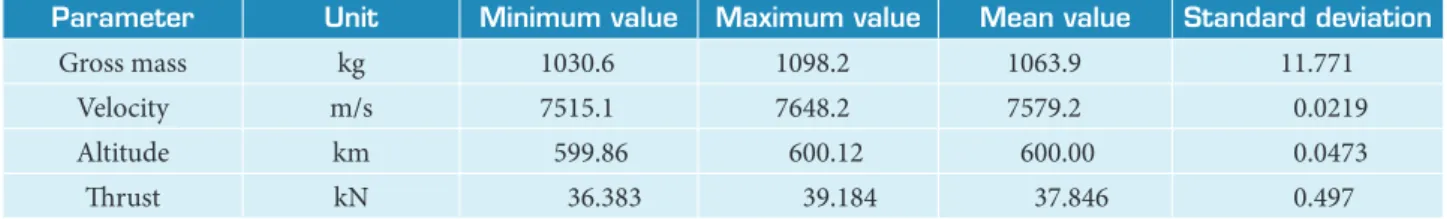
Monte Carlo analysis is widely used in system and early stage of design. It provides a relatively accurate statistical evaluation of the response distribution under input uncertainties. Monte Carlo sensitivity analyses of the main KSRM parameters were conducted to investigate the effect of uncertainties of design variables over the expected result. For this analysis, a ±1% error was added to every optimized value of design variables. The results are presented in Table 6, and the scatter plot is shown in Fig. 6.
Figure 6. Monte Carlo sensitivity analysis. 1120
1100
1060 1080
1040
1020
1000
0 200 400 600 800 1000
Monte Carlo runs
G
ros
s m
as
s (kg)
7.7
7.65
7.6
7.65
7.5
7.45
0 200 400 600 800 1000
Monte Carlo runs
V
elo
ci
ty (k
m/s)
600.2
600.1
600
599.5
599.8
0 200 400 600 800 1000
Monte Carlo runs
A
lt
it
ude (k
m)
Monte Carlo runs 40
39
38
37
36
35
0 200
T
h
r
u
s
t (kN)
400 600 800 1000
0.8
0.6
0.4
0.2
0
0 10 20 30 40 50
Time(s)
N
o
rm
al o
ver
lo
ad
1200
1000
800
600
400
200
0 10 20 30 40 50
Time(s)
G
ros
s m
as
s (kg)
40
39
38
37
36
0 10 20 30 40 50
Time(s)
Th
ru
s
t (KN)
14
12
10
8
6
4
0 10 20 30 40 50
Time(s)
A
xi
al o
ver
lo
ad
CONCLUSION
A GA based optimization approach has been applied
to conceptual design and optimization of a KSRM. he advantage of the GA relied on its independency of initial point to calculate the optimum. A 2D dynamic model was developed to simulate the orbital insertion trajectory of the upper stage composed of the PDM of 100 kg, the optimized a payload of 200 kg. A sensitivity analysis was conducted using Monte Carlo method to investigate the variation of the main parameters of the KSRM. he emphasis of this research was to ind the optimal KSRM design and the upper stage insertion
trajectory proile characteristics required for insertion a small payload into a circular LEO orbit of 600 km.
he results of the KSRM parameters are shown in Tables 4 and 5 and its insertion trajectory proile is shown in Figs. 4 and 5, and Monte Carlo sensitivity analysis shown in Fig. 6 evidenced the validity of the used approach for the early stage of the design process.
ACKNOWLEDGMENTS
Fredy Villanueva wishes to thank Beihang University and China Scholarship Council (CSC), for inancial support.
REFERENCES
Anderson M.B., Burkhalter, J. and Jenkins, R., 2001, “Multi- Disciplinary Intelligent Systems Approach to Solid Rocket Motor Design. Part I: Single and Dual Goal Optimization”, 37th AIAA/ASME/SAE/ASEE Joint Propulsion Conference and Exhibit, AIAA, paper 2001-3599.
Bayley, D.J. and Hartfield, R.J., 2007, “Design Optimization of a Space Launch Vehicles for Minimum Cost using a Genetic Algorithm”, AIAA 43rd AIAA/ASME/SAE/ASEE Joint Propulsion Conference and Exhibit, AIAA, paper 2007-5852.
Casalino, L., Pastrone, D. and Simeoni, F., 2011, “Hybrid Rocket Upper Stage Optimization: Effects of Grain Geometry”, AIAA 47th AIAA/ASME/SAE/ASEE Joint Propulsion Conference and Exhibit, AIAA, paper 2011-6024.
Davis, L., 2001, “The Handbook of Genetic Algorithm”, Van Nostrand Reingold, New York.
Fleeman, L.E., 2001, “Tactical, Missile Design”, AIAA, Reston.
Fletcher, R., 2000, “Practical Methods of Optimization”, John Wiley & Sons.
Goldberg, D., 1989, “Genetic Algorithm in Search, Optimization and Machine Learning”, first edition, Addison-Wesley–Longman Publishing Co., Reading, MA.
He Linshu, 2004a, “Launch Vehicle Design”, Beijing University of Aeronautics and Astronautics Press, Beijing.
He Linshu, 2004b, “Solid Ballistic Missile Design”, Beijing University of Aeronautics and Astronautics Press, Beijing.
He Linshu and Murad Y., 2005, “An Improved Method for Conceptual Design of Multistage Solid Rockets based on Depleted Shutdown”, Journal of Solid Rocket Technology, Vol. 28, No 2, paper 120-125.
Kamran, A., Lian, G., Godil, J., Siddique, Z., Zeeshan, Q. and Rafique, A., 2009, “Design and Performance Optimization of Finocyl Grain”, AIAA Modeling and Simulation Technologies Conference 10 -13 August 2009, Chicago, Illinois, AIAA, paper 2009-6234.
McGinnis, P.M. and Joyner, C.R., 2005, “Upper Stage Propulsion Options for Various Launch Vehicle Architectures”, AIAA 41st AIAA/ ASME/SAE/ASEE Joint Propulsion Conference and Exhibit, AIAA, paper 2005-4180.
Motlagh, J.A. and Novinzadeh, A.B., 2012, “Solid Upper Stage Design Process using Finite Burn Maneuvers for Low Earth Orbit– Geosynchronous Earth Orbit Transfer Phase”, Institution of Mechanical Engineers, Part G: Journal of Aerospace Engineering.
Table 6. Monte Carlo results.
Para meter Unit Minimum value Maximum value Mean value Standard deviation
Gross mass kg 1030.6 1098.2 1063.9 11.771
Velocity m/s 7515.1 7648.2 7579.2 0.0219
Altitude km 599.86 600.12 600.00 0.0473
Qazi, M. and He Linshu, 2005, “Rapid Trajectory Optimization using Computational Intelligence for Guidance and Conceptual Design of Multistage Space Launch Vehicles”, AIAA Guidance, Navigation, and Control Conference and Exhibit, AIAA, paper 2005-6062.
Rafique, A.F., He Linshu, Zeeshan, Q., Kamran, A., Nisar, K. and Wang, X.W., 2009, “Integrated System Design of Air Launched Small Space Launch Vehicle using Genetic Algorithm”, 45th AIAA/ASME/SAE/ASEE Joint Propulsion Conference and Exhibit, AIAA, paper 2009-5506.
Riddle, D.B., Hartfield, R.J., Burkhalter, J.E. and Jenkins, R., 2007, “ Genetic Algorithm Optimization of Liquid Propellant Missile Systems”, AIAA Aerospace Sciences Meeting and Exhibit, AIAA, paper 2007-0362.
Sutton, G.P. and Biblarz, O., 2001, “Rocket Propulsion Elements”, Wiley-Interscience, New York.
Tedford, N.P. and Martins, J.R., 2010, “Benchmarking Multidisciplinary Design Optimization Algorithms”, Optimization and Engineering, Vol. 11, No 1, paper 159-183.
Xiao, Y.I., 2001, “Rocket Ballistics and Dynamics”, Beijing University of Aeronautics and Astronautics.