145
Abstract
This paper aims to present an elastic, perfectly plastic, constitutive model based on the Hoek-Brown failure criterion and with non-associative plasticity. The objective is to apply the model to the non-linear analysis of geotechnical problems like excavations in rock mass. The computational implementation was carried out with a computational program called ANLOG (Non-Linear Analy-sis of Geotechnical Problem) system based on a displacement formulation of the inite element method. Due to the non-linear nature of the constitutive model, the study adopts an incremental iterative Newton-Raphson procedure with auto-matic load increments to guarantee the global level equilibrium. In addition, to guarantee the consistency condition at the local level, the study adopts, for the stress integration, an explicit algorithm with automatic sub-increments of strain. To validate the computational implementation and applicability of the numerical model, the study uses theoretical results to compare with ones obtained with the numerical simulation of cylindrical cavity in rock mass.
Keywords: Hoek-Brown failure criterion, inite element method, elastoplasticity, stress integration algorithm, cylindrical cavity, tunnel, rock mass.
Resumo
Esse artigo apresenta um modelo constitutivo elástico perfeitamente plás-tico com plasticidade associada e com base no critério de resistência de Hoek--Brown. O objetivo é aplicar esse modelo para análise não linear de problemas geotécnicos como escavações em maciços rochosos. As implementações compu-tacionais foram realizadas no sistema ANLOG (Análise não linear de obras ge-otécnicas) com base na formulação em deslocamento do método dos elementos initos. Devido à natureza não linear do modelo constitutivo, o estudo adota um procedimento incremental iterativo do tipo Newton-Raphson com incrementos automáticos de modo a garantir o equilíbrio em nível global. Além disto, para garantir a condição de consistência em nível local, o estudo adota um esquema de explicito de integração de tensão com subincrementos automáticos de defor-mação. Para validar as implementações computacionais e a aplicabilidade do modelo numérico gerado, o estudo usa os resultados da simulação numérica de uma cavidade cilíndrica em maciços rochosos.
Palavras-chave: Critério de ruptura de Hoek-Brown, método dos elementos initos, elastoplasticidade, algoritmo de integração de tensão, cavidade cilíndrica, túnel, maciço rochoso.
Non linear elasto-plastic analysis
of cylindrical cavity in rock mass
using a Hoek-Brown criterion
Análise não linear elastoplástica
de cavidades cilíndricas em maciços
rochosos usando o critério de Hoek-Brown
Jefferson Tales Simão Mestrando
Universidade Federal de Ouro Preto – Escola de Minas – Departamento de Engenharia de Minas – Programa de Pós-Graduação em Engenharia de Minas – PPGEM
Christianne de Lyra Nogueira Professora Associada IV da Universidade Federal de Ouro Preto – Escola de Minas – Departamento de Engenharia de Minas – Programa de Pós Graduação em Engenharia de Minas – PPGEM [email protected]
Civil Engineering
Engenharia Civil
REM: R. Esc. Minas, Ouro Preto, 68(2), 145-152, apr. jun. | 2015
146
1. Introduction
The application of the inite ele-ment method (FEM), which considers a continuous media, to analyze the me-chanical behavior of a rock mass has been restricted to hard rock or non-fractured rock mass. Due to the increasing number of geotechnical works carried out on frac-tured rock masses, it has become neces-sary to use a constitutive model that takes into account the geological condition of
a rock mass. Such a model is capable of providing more realistic results when us-ing a displacement formulation of FEM. In the early 1980’s, the Hoek-Brown failure criterion was developed for hard rock (Hoek and Brown 1980). Since then, several versions have been published in order to include the inluence of geological conditions on the failure pa-rameter of rock masses (Hoek and Brown
1988; Hoek et al 1992, 1995, 2002). The use of a Hoek-Brown failure criterion, as the yield function in an elastic-plastic analysis, leads to the appli-cation of an incremental iterative proce-dure at the global level of a FEM analysis and the application of a stress integration scheme at the local level (Sharan 2003; Sharan 2005; Clausen and Dumkilde 2008; Wang and Yin 2011).
2. Hoek-Brown elasto-plastic model formulation
The equilibrium equations of a mechanical problem, in static condi-tion, describe a non-linear equation system when adopting an elasto-plastic stress-strain-strength relationship
(Teixeira et al 2012). During a given equilibrium path, the variation on the displacement, strain, and stress ields depends on the stress and strain levels and their history through the
equilib-rium path.
Based on the displacement inite element formulation, the equilibrium equations can be written as:
F
int=
F
ext (1)(2)
(3)
(4)
(5)
(6)
(7)
(8) Where,
F
ext is the external nodal forcevec-tor that represents the global arrangement
of the element external nodal force vector
F
e deined as:in which ffff represents the parcel of external nodal force due to surface load; ffff represents the parcel of external nodal force due to body force, ffff and
represents the parcel of external nodal force due to non-null prescribed dis-placements, δ.
F
int is the internal nodal force vector that represents the globalarrangement of the element internal nodal force vector ffff equivalent to the stress state σ in a given element that is deined as:
F
exteF
exte=
F
Se+
F
be+
F
δeF
SeF
beF
δeF
inteF
int=
∫
B
Tσ
dV
e eVe
Due to the non-linear nature of the equation system represented by Equation (1), an incremental-iterative procedure should be used in order to obtain the displacement, strain, and stress ields. Then, starting from a given equilibrium
coniguration
n
, where the stress and strain states are known, a predicted incremental solution in terms of the global displacement (ΔÛ
on
) is obtained.
This predicted approximation should be corrected by successive iteration (δΔ
Û
) until reaching a new equilibrium
conigurationn
+1 (Crisield 1991). In this strategy, the problem solution is obtained by updating the nodal displace-ment vector (Û
) in each new equilibrium coniguration, by doing:B
is the cinematic matrix which depends on the strain-displacement relationship.Û
n+1=
Û
n+
Û
kΔ
Û
k= Δ
Û
οn
+
∑
δΔ
Û
kk =1 iter
Where,
Δ
Û
on
= [
K
ep]
-1
Δ λ
F
extδ Δ
Û
k= [
K
ep
]
-1Ψ
kΨ
k=
F
ext k
-
F
int k
iter is the necessary iterative cycle number to reach convergence at the current step, while Δλ is the increment of load factor, which can be
automati-cally deined starting from the initial trial provided by the user (Nogueira 1998; Oliveira 2006; Simão 2014).
K
ep is the global stiffness matrix that147
where,D
ep is the elasto-plasticconstitu-tive matrix which depends on the
stress-strain-strength relationship. According to the Modiied Newton-Raphson iterative
scheme the global stiffness matrix is kept constant during the iterative cycles.
The vector
F
extk represents the exter-nal nodal force applied at each load stepand kept constant throughout the iterative cycles, according to the Newton-Raphson
iterative scheme. This vector is updated at the beginning of a given step load by: (9)
(10)
(11)
(12)
(13)
(14)
(15)
(16)
(17)
(18)
(19)
K
ep=
∫
B
TD
ep
B
dV
e eF
extk=
F
ext n
+
Δ λ
F
ex whereF
ext n is the external nodal forcevector at a given equilibrium coniguration
n
. The internal nodal force vectorF
intk is evaluated at each iterative cycle dependingon the stress state evaluated at this itera-tive cycle,
σ
k.At the end of each iterative cycle, a convergence state of the solution is veri-ied by using a criterion that relates the Euclidian norm of the unbalance nodal force vector with the Euclidian norm of
the external nodal force vector. Thus, for a given tolerance and at each increment, the iterative scheme ensures the overall balance by satisfying the compatibility conditions, boundary conditions and
con-stitutive relationships.
This iterative scheme involves the stress state evaluation at each iterative cycle. Then, in each element, the stress vector
σ
k is obtained by:σ
k=
σ
n+
Δ
σ
k
σ
k=
D
epΔ
ε
k Where,
Δ
ε
k= -
B
Δ
Û
kand, Δ
Û
k is the incremental displacement vector at element level and updated at the current iterative cycleBy adopting linear elastic, per-fectly plastic (which is free of harden-ing durharden-ing the plastic low) and with
the associated plasticity (in which the potential plastic and yield functions are the same) constitutive model, the
elasto-plastic constitutive matrix can be written as:
D
ep=
D
e-
D
eT(
a
Ta
)
(
a
TD
ea
)
D
ewhere,
D
e is the elastic constitu-tive matrix which depends on the young modulus (E
) and Poisson coeficient (ν). The vectora
is the gradient of the yieldfunction (
F
) which depends on the failure criterion used.This paper adopts the generalized Hoek-Brown failure criterion (Hoek et al
2002) written in terms of principal stress,
σ
1 andσ
3, as:(
σ
1 -σ
3)
=σ
ci[
mb (
σ
3 /σ
ci ) + S ] aIn which
σ
ci is the uniaxial compres- sive strength of intact rock, andm
b,a
ands
are constants deined as:m
b= m
ie
(GSI - 100)/(28 - 14D)s
= e
(GSI - 100)/(9 - 3D)a = 0.5 + (e
- GSI/15)/(9 - 3D)- e
-20/3)/6
Where,m
i is a constant of Hoek-Browncriterion intact rock;
D
is a disturbance coefficient which varies from 0.0 for undisturbed in situ rock mass to 1.0 forvery disturbed rock mass, and GSI is the Geological Strength Index, which takes into account the geological condition of the rock mass.
As no hardening occurs in a perfect-ly plastic constitutive model and the yield concept merges with the failure concept, the yield function can be written as:
F = F (
σ
) = 0
REM: R. Esc. Minas, Ouro Preto, 68(2), 145-152, apr. jun. | 2015 148
(
)
0
s
3
I
m
sen
3
1
cos
θ
m
I
2cos
θ
I
)
,
I
,
I
(
F
b 1 cib 2D a / 1 ci 2D ci D 2
1
⎟
−
−
σ
=
⎠
⎞
⎜
⎝
⎛
θ
+
+
⎥
⎥
⎦
⎤
⎢
⎢
⎣
⎡
σ
σ
=
θ
(20) (21) (22) (23) (24) (25) (26) (27) (28) where,I
is the irst invariant of thestress tensor;
I
2D is the second invariant of the deviator stress tensor, and θ is the Lode angle that depends on the second and the third (I
3D) invariant of deviator stress tensor (Owen and Hinton 1989).In theory, at each increment and for a selected tolerance, the iterative scheme satisies the global equilibrium
equations, the compatibility and bound-ary conditions, and the constitutive equations. However, the constitutive equation integration is not trivial, even if one knows the incremental strain magnitude on each iterative cycle, what is still unknown is the way it varies across the incremental path. It is nec-essary then to use an accurate stress
integration algorithm.
It is possible, by adopting the ex-plicit stress integration scheme as sug-gested by Sloan et al (2001), to increase the precision of the stress calculation. According to these authors the incre-ment of stress can be divided into two parcels: elastic, Δ
σ
e , and elastic plastic,Δ
σ
ep , such as:Δ
σ
k=
Δ
σ
e + Δ
σ
ep=
α
D
eΔε
+
Δ
σ
ep where, α is a scalar that varies from 0 to
unity. For α = 0 the strain increment gen- erates an elastic plastic stress increment. For
α = 1 the strain increment generates a
purely elastic stress increment. The α sca-lar value is obtained by solving iteratively:
|F (
σ
n+
α
D
eΔ
ε
|
≤
FTOL
where
FTOL
is the tolerance sug-gested by Sloan et al, (2001) as 10-5. Oncedeined, the α scalar, the stress state upon the yield surface, is updated according to:
σ
int=
σ
n+
Δ
σ
eσ
j=
σ
j - 1+ d
σ
epj The increment of elastic plastic stress is obtained by:
d
σ
epj=
D
ep(
σ
j
)
d
ε
epj
d
ε
epj=
Δ
T
jΔ
ε
epΔ
ε
ep= ( 1-
α
)
Δ
ε
whereΔ
T
j is a scalar known as incrementof pseudo-time (
T
) that varies from zero to unity and is evaluated while taking into account the local error committed during the stress integration. This error cannotexceed a
STOL
tolerance. The irst trial is conducted by adopting ΔT
= 1. The procedure is controlled by pseudo-timeT
(0≤T≤1) at the end of each subincrement,
Σ
Δ
T = T
= 1. The stress state is updated
at the end of each sub increment starting from stress state upon the yield function (
σ
0=
σ
int). The procedure described in this paper was implemented into ANLOG (Nogueira 2010) by Simão (2014).3. Cylindrical cavity in elasto-plastic rock mass
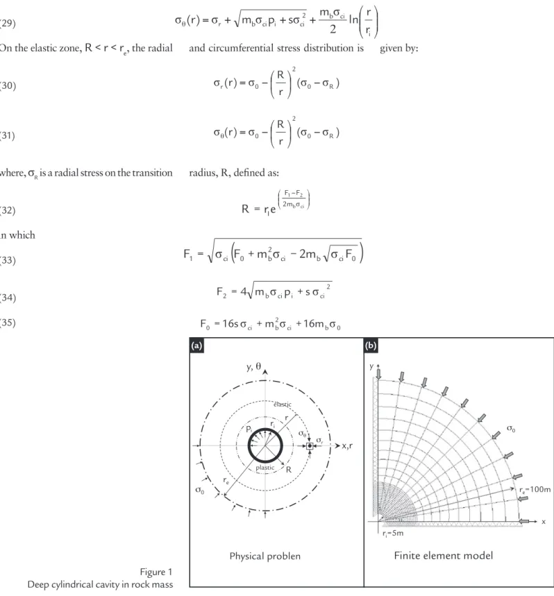
This item describes the numerical simulation of a cylindrical cavity in a semi-ininite rock mass. The main goal of this simulation is to establish the plastic and elastic zones around the cavity and its stress distribution, highlighting the inlu-ence of the pressure acting internally on the cavity wall.
The problem is depicted in Figure 1 and consists of a cylindrical cavity of internal radius, ri, deeply conducted in a rock mass considered homogeneous,
iso-tropic, and subjected to a isotropic initial stress state,
σ
0. The stress-strain behavior of the rock mass is represented by using non-linear elastic-perfectly plastic, with associate plasticity, based on the Hoek-Brown criterion constitutive model as presented in the previous item. The elasto-plastic transition radius,R
, deines a zone with plastic behavior(R-r
i)
around the cavity and the external radius,r
e, deines the dominium of the problem.Sharan (2003, 2005) and Park and
Kim (2006) presented an analytical solu-tion for this problem considering the rock mass, under isotropic initial stress state, as elastic-brittle-plastic material which presents a sudden loss of strength after reach its maximal value. In this paper, this solution is adapted to consider an elastic perfectly plastic material which does not present this sudden loss of strength. Then, the radial and circumferential stress dis-tribution on the plastic zone,
r
i<r<R
, is given by: i 2 ci i ci b i 2 ι ci br
m
σ
p
s
σ
p
r
r
l
n
r
r
l
n
4
σ
m
)
r
(
σ
⎥
+
+
149
⎟⎟
⎠
⎞
⎜⎜
⎝
⎛
+
+
+
=
θ i ci b 2 ci i ci b rr
r
ln
2
σ
m
s
σ
p
σ
m
σ
)
r
(
σ
(29) (30) (31) (32) (33) (34) (35)On the elastic zone,
R < r < r
e, the radial and circumferential stress distribution is given by:)
σ
(
σ
r
R
σ
)
r
(
σ
0 R2
0
r
⎟
−
⎠
⎞
⎜
⎝
⎛
−
=
)
σ
(
σ
r
R
σ
)
r
(
σ
0 R2
0
θ
⎟
−
⎠
⎞
⎜
⎝
⎛
−
=
where,
σ
R is a radial stress on the transition radius, R, deined as:⎟⎟ ⎠ ⎞ ⎜⎜ ⎝ ⎛ −
=
b ci 2 1 σ 2m F F Ie
r
R
in which(
ci b ci 0)
2 b 0 ci
1
σ
F
m
σ
2
m
σ
F
F
=
+
−
2 ci i ci b
2
4
m
σ
p
s
σ
F
=
+
0 b ci 2 b ci
0 16sσ m σ 16m σ
F = + +
x,r y,θ ri pi R re σ0 σr σθ r elastic plastic
re=100m
ri=5m
x y
σ0
Physical problen Finite element model
Figure 1 presents the inite element mesh used in the numerical simulation; it is composed of 220 quadrilateral qua-dratic isoparametric elements
(Q8)
and 661 nodal points. The following constitu-tive parameters were adopted:E =
5.5GPa;ν = 0.25;
σci = 30MPa;m
b = 1.7;s
= 0.0039;a
=0.5 (which correspond to a GSI = 50 andm
i = 10, approximately).The study uses a modiied Newton-Raphson incremental iterative procedure with automatic increment of load (
I
d = 10, miter = 20; toler = 0.1%; Δλ0 = 0.01;Δλ
min = 10-6;Δλ
max = 10
-2) and a Forward
Euler stress integration (FTOL = 10-5 and
STOL = 10-2).
Figure 2a illustrates the analytical and numerical (y = 0) results along the radial direction in terms of the radial (
σ
r) and circumferential (σ
θ) stresses, consid-ering an initial isotropic stress state (σ
0) of 30MPa and a null internal pressure (p
i). Table 1 presents the normalized elasto-plastic transition radius (R/r
i) and stresses. As can be observed, numerical and analytical solutions agree strongly.Figure 2b shows an elastic analyti-cal solution provided by Kirsch (Poulos and Davis 1972) of a circular opening considering a horizontal stress coeficient of one. In this case, the circumferential stress decreases along the radial direction, while the radial normal stress increases in this direction. The elastic analysis overestimates the circumferential stress on the wall cavity. The elasto-plastic so-lution presents an abrupt decrease in the circumferential stress on the elasto-plastic transition zone.
Figure 1 Deep cylindrical cavity in rock mass
REM: R. Esc. Minas, Ouro Preto, 68(2), 145-152, apr. jun. | 2015
150
Solution R/ri σr/σ0 σθ /σ0 σz /σ0
Analytical 2.833 0.526 1.474 0.500
Numerical 2.893 0.568 1.400 0.492
Table 1
Elasto-plastic transition radius and stress (pi = 0MPa and ri = 5m)
Figure 2
Stress distribution
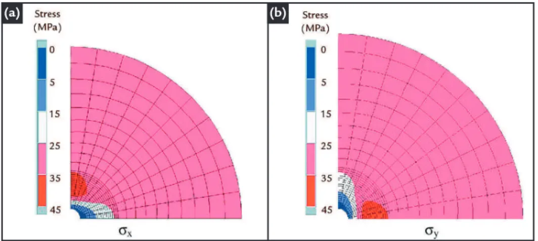
Figure 3 presents a stress distribution around the cavity in terms of the isocurve
of stress components. The highest vertical stress level is observed near the lateral wall
of the cavity while the highest horizontal stress level is observed near its roof (Fig. 3)
Figure 3
Stress distributions – pi = 0
0 1 2 3 4 5 6 7 8 9 10
r/r 0
0.25 0.5 0.75 1 1.25 1.5 1.75 2
N
o
rm
a
li
z
e
d
S
tr
e
ss
/ 0 (A nalytical) r/ 0(Analytical) / 0 (Numerical) r/ 0(Numerical) Elastic solution
r/ 0 / 0
Elastic-plastic solutions
0 1 2 3 4 5 6 7 8 9 10
r /ri 0
0.25 0.5 0.75 1 1.25 1.5 1.75 2
N
o
rm
a
li
z
e
d
S
tr
e
s
s
/ 0 pi/0 = 0.0
pi/0 = 0.2
pi/0 = 0.5
r/ 0 pi/0 = 0.0
pi/0 = 0.2
pi/0 = 0.5
Numerical elastic-plastic solutions
pi/σ0= varying
pi/σ0= 0
(a)
(b)
151
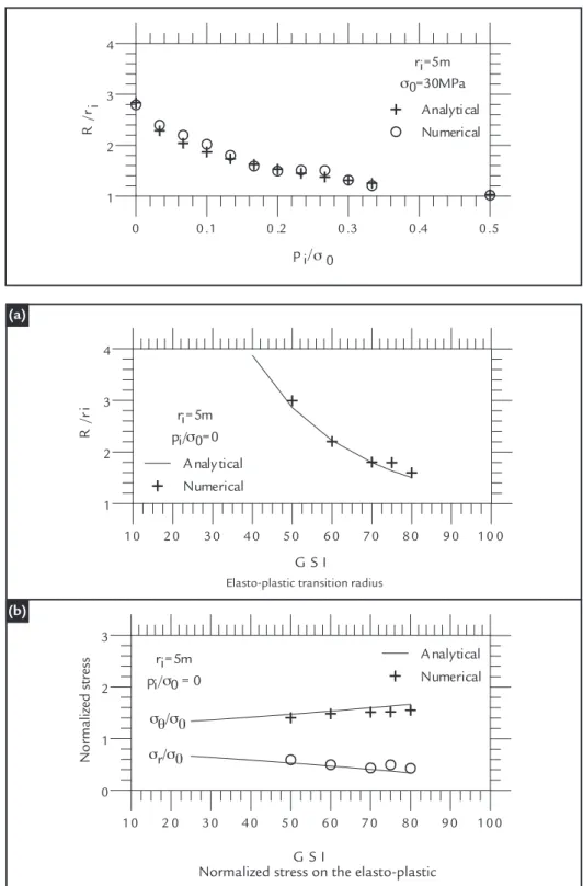
Figure 5Influence of GSI Figure 4 Elasto-plastic transition radius - pi varying
Figure 4 shows the inluence of the internal pressures acting on the in-ternal wall cavity on the elasto-plastic transition radius. No plastic zone is observed from the internal pressure on the order of magnitude around half of the initial isotropic stress. The highest elasto-plastic transition radius is
ob-served in an unsupported excavation, represented in this paper by a null in-ternal pressure. In this case the radius depends on the property’s material and the cavity radius.
Figures 5a and 5b show the inlu-ence of the GSI on the elasto-plastic transition radius and on the normal
radial and circumferential stresses at this point. As was expected, the elasto-plastic transition radius de-creases as the GSI inde-creases. Related to normal stresses, the radial stress decreases as the GSI increases, while the circumferential stress increases as the GSI increases.
0 0 .1 0 .2 0 .3 0 .4 0 .5
p i/σ0 1
2 3 4
R
/ri
ri=5m
σ0=30MPa
Analytical Numerical
1 0 2 0 3 0 4 0 5 0 6 0 7 0 8 0 9 0 1 0 0
G S I
1 2 3 4
R
/r
i
ri=5m pi/σ0=0
A naly tical Numerical
1 0 2 0 3 0 4 0 5 0 6 0 7 0 8 0 9 0 1 0 0
G S I
0 1 2 3
A nalytical Numerical ri=5m
pi/σ0 = 0
σθ/σ0 σr/σ0
Elasto-plastic transition radius
Normalized stress on the elasto-plastic transition radius
Normalized str
ess
5. Conclusion
The results presented in this paper demonstrated the importance of using the FEM and elastic-plastic constitutive model to simulate the opening cavity in
rock masses. It was shown, for instance, that the stress distribution on the support structure changes signiicantly. By using the computer program ANLOG, it is
pos-sible to perform parametric studies for a wide variety of materials and geometrical coniguration to improve the design of tunnel support.
(a)
REM: R. Esc. Minas, Ouro Preto, 68(2), 145-152, apr. jun. | 2015
152
Received: 19 March 2014 - Accepted: 18 August 2014.
CLAUSEN, J., DAMKILDE, L. An exact implementation of the Hoek–Brown crite-rion for elasto-plastic, inite element calculations. International Journal of Rock Mechanics & Mining Sciences, v. 45, n. 6, p. 831–847, 2008.
CRISFIELD, M. Nonlinear inite element analysis of solids and structures. John Wi-ley and Sons, 1991.
HOEK, E. Strength of rock and rock mass. ISRM New journal, v. 2, n. 2, p. 4-16, 1994.
HOEK, E., WOOD, D., SHAH, S. A modiied Hoek-Brown criterion for jointed rock mass. Proc. In: ROCK CHARACTERIZATION SYMPOSIUM, EUROCK’92, London, p.209-214, 1992.
HOEK, E., BROWN, E.T. Underground excavation in rock. London: Institution of Mining and Metallurgy, 1980.
HOEK, E., BROWN, E.T. The Hoek-Brown failure criterion – a 1988 update. In: Rock Engineering for underground excavation, Proc. In: CANADIAN ROCK MECHANICS SYMPOSIUM, 15. Toronto: University of Toronto, p. 31-38, 1988. HOEK, E., CARRANZA-TORRES, C., CORKUM, B. Hoek-Brown failure criterion
– 2002 edition, In: NORTH AMERICAN ROCK MECHANICS SYMPOSIUM, 15. Proc., TUNNELING ASSOCIATION OF CANADA CONFERENCE, 17. p.267-271, 2002.
HOEK, E., KAISER, P.K, BAWDEN, W. F. Support of underground excavation in hard rock. Rotterdam: Balkema, 1995.
NOGUEIRA, C. L. Análise não linear de escavações e aterros. Rio de Janeiro: De-partamento de Engenharia Civil, Pontifícia Universidade Católica do Rio de Janei-ro (PUC-Rio), 1998. 250 f. (Tese de Doutorado)
OLIVEIRA, R. R. V. Análise elastoplástica via MEF de problemas em solos refor-çados. Ouro Preto: Escola de Minas, Universidade Federal de Ouro Preto (UFOP), 2006. 143 f. (Dissertação de Mestrado em Engenharia Civil). OWEN, D.R.J. , HINTON, E. Finite elements in plasticity: theory and practice. Swansea, U.K.: Pineridge Press, 1980.
POULOS, H. G., DAVIS, E. H. Elastic solution for soil and rock mechanics. John Willey Ed., 1972.
PARK, K-H., KIM, Y-J. Analytical solution for a circular opening in an elastic–brit-tle–plastic rock. International Journal of Rock Mechanics & Mining Sciences, v. 43, n.4, p.616-622, 2006.
SHARAN, S. K. Elastic-brittle plastic of circular opening in Hoek brown media. In-ternational Journal of Rock Mechanics & Mining Sciences, v. 40, n. 6, p. 817-824, 2003.
SHARAN, S.K. Exact and approximate solutions for displacements around circular openings in elastic–brittle–plastic Hoek–Brown rock. International Journal of Rock Mechanics & Mining Sciences, v. 42, p. 542-549, 2005.
SLOAN, S. W., ABBO, A. J., SHENG, D. Reined explicit integration of elasto-plastic models with automatic error control. Engineering Computations, v. 18, n. 1/2, p. 121-154, 2001.
TEIXEIRA, M.B., NOGUEIRA, C.L., OLIVEIRA FILHO, W.L. Numerical Simula-tion of Hillside Mine Waste Dump ConstrucSimula-tion. REM: Revista Escola de Minas, v. 65, n. 4, p. 553-559, 2012.
SIMAO, J. T. Um modelo numérico para análise elastoplástica de maciços rochosos com base no critério de ruptura de Hoek-Brown. Ouro Preto: Escola de Minas, Universidade Federal de Ouro Preto (UFOP), 2014. 90 f. (Dissertação de Mestrado em Engenharia Mineral).
WANG, S. & YIN, S. A closed-form solution for a spherical cavity in the elastic–brittle–plastic medium. Tunneling and underground space technology, n.26, p.236-241, 2011.
7. References
6. Acknowledgments
The authors are grateful for the inancial support received from CAPES,
CNPq, and FAPEMIG. The irst author is grateful for the grant received by CAPES.