Cold Spray Deposition
of WC-Co
Mestrado Integrado em Engenharia Metalúrgica e de Materiais
Miguel Pereira de Magalhães e Couto; Nº. de aluno: 06050819 Porto, 13 de Julho de 2011
Faculdade de Engenharia da Universidade do Porto
Dissertação orientada por:
Professor Fernando Jorge Monteiro – Faculdade de Engenharia da Universidade do Porto Professor Josep Maria Guilemany – Centre de Projecció Tèrmica, Universitat de Barcelona
realidad. Cuando comprendes esto, ves que no eres nada, y siendo nada, eres todo.” Octavio Paz, in El laberinto de la soledad
À FEUP e ao DEMM por ajudar-me a evoluir durante estes cinco intensos e rápidos anos. Ao Professor Luís Filipe Malheiros por me ter sugerido este estágio e principalmente ao Professor Fernando Jorge Monteiro e à sua constante boa disposição. Ao Professor Guilemany pelas oportunidades que me ofereceu até hoje e ao Doutor Sergi Dosta, por toda a simpatia e tranquilidade, que me aturou durante este período e partilhou comigo o seu extenso e profundo conhecimento de Cold Spray.
Também devo mostrar todo o meu agradecimento ao pessoal do CPT: David, Jessica, Victor Crespo, Victor Gómez, à Nuria, ao Marc Torrell e à María por fazerem tão simples a minha adaptação e por toda a ajuda que me deram nos primeiros meses. Ao Marc Gardon por me ajudar a manter os pés na terra e a pouca lucidez que me resta (e a ele) na cabeça.
Ao Gustavo Cerati que tanta inspiração musical me deu e que espero do fundo do coração que melhore rapidamente. La tierra te extraña, hombre alado.
À Doutora Manuela Costa Pinto em quem vi, pela primeira vez na vida, uma verdadeira demonstração de coragem e positivismo inspiradores.
Ao Diogo Sá e ao Daniel Silva, os meus inseparáveis companheiros de estudo, de grupo, que tanto me ensinaram, e mais que ninguém, me viram crescer.
Ao Miguel Trevisan, que me conhece há mais tempo que eu próprio, e que nunca deixou de estar ao meu lado em todos os momentos: quero agradecer-lhe como a um irmão. Ao João Moura por ser uma pessoa com a qual sei que poderei contar e confiar sempre. Com eles o sol sempre deu a volta mais rápido.
À avó Teresa e avó Beatriz, constantes presenças espirituais. Ao André por fazer-me sempre sentir especial.
À Ingrid, que mesmo a 9000km de distância durante um semestre me deu forças e coragem inimagináveis; que me mostrou que nada é impossível e que as culturas e fronteiras não existem mais como barreiras; a ela devo o meu sucesso actual, em cada vez que me fez ver e compreender que subir para o próximo nível é ser mais. A sua bravura poderia ser distribuída por mil pessoas e, ainda assim, fazer corar o mais valente.
Ao Pai por nos ter proporcionado sempre as melhores oportunidades e nos ter posto em todos os momentos em primeiro lugar. Sem ele não teria aprendido a valorizar. À Mãe por ser a pessoa mais incrível, mais esforçada, mais humana, mais capaz de romper todos os limites por amor, e por nunca ter deixado de acreditar em mim. As próximas páginas são mais vossas que minhas e sei que vos encho de orgulho. Obrigado.
LIST OF FIGURES LIST OF TABLES ABSTRACT
1 – SUBSTRATE MATERIALS 1
1.1 – LOW CARBON STEELS 1
1.2 – ALUMINIUM 2
2 – COMPOSITES DEPOSITION 2
2.1 – CONVENTIONAL THERMAL DEPOSITION TECHNIQUES 3
2.1.1 – PLASMA SPRAY TECHNIQUES 4
2.1.2 – HIGH VELOCITY OXYGEN FUEL 6
2.2 – ADVANTAGES 7
2.3 - LIMITATIONS 8
3 – THE COLD SPRAY PROCESS 8
3.1 – ADVANTAGES 11
3.2 – LIMITATIONS 12
3.3 – PROCESS PARAMETERS 13
3.3.1 – PARTICLE VELOCITY 14
3.3.2 – PARTICLE, GAS AND SUBSTRATE TEMPERATURE 15
3.3.3 – POWDER SIZE, MORPHOLOGY AND DENSITY 17
3.3.4 – POWDER FEEDING RATE 17
3.3.5 – SPRAYING ANGLE 18
3.3.6 – NOZZLE-SUBSTRASTE STANDOFF DISTANCE 19
3.3.7 – SUBSTRATE ROUGHNESS AND THICKNESS 21
3.4 – BONDING MECHANISM 22 4 – EXPERIMENTAL PROCEDURE 25 4.1 – STRUCTURAL CHARACTERIZATION 25 4.1.1 – FEEDSTOCK POWDERS 26 4.1.2 – COATINGS 26 4.2 – ADHESION TESTS 26 4.3 – WEAR TESTS 26
4.3.1 – SLIDING WEAR TESTS 26
4.3.2 – ABRASIVE WEAR TESTS 27
4.4 – ELECTROCHEMICAL TESTS 27
5 – APPLICATIONS 27
6 – OBJECTIVE OF THE EXPERIMENTAL WORK 28
7 – RESULTS AND DISCUSSION 30
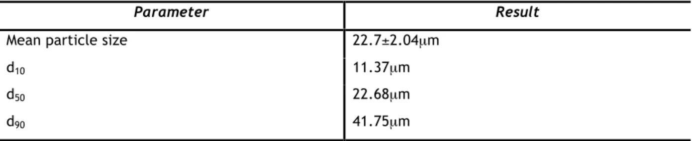
7.1 – POWDER CHARACTERIZATION 31
7.1.1 – PARTICLE SIZE DISTRIBUTION 31
7.1.2 – STRUCTURAL CHARACTERIZATION BY SEM 32
7.1.3 – STRUCTURAL CHARACTERIZATION BY XRD 33
7.1.4 – STRUCTURAL CHARACTERIZATION BY EDS 34
7.2 – COATINGS CHARACTERIZATION 35
7.3 – ADHESION TESTS 43
7.4 – TRIBOLOGICAL PROPERTIES 46
7.4.1 – SLIDING TESTS (BALL-ON-DISK) 46
7.4.2 – ABRASIVE TESTS (RUBBER-WHEEL) 48
7.5 – ELECTROCHEMICAL TESTS 49
8 – CONCLUSIONS 52
9 - FUTURE PERSPECTIVES 54
Figure 1 - Schematic diagram of the plasma spray process. 5 Figure 2 - Operational sequence of a Pulsed Plasma Spray. 5
Figure 3 - Schematic diagram of a HVOF spray gun. 7
Figure 4 - Schematic diagram of the cold spray process. 9
Figure 5 - Diagram of a de Laval nozzle showing approximate flow velocity (v), together with the
effect on temperature (T) and pressure (P). 11
Figure 6 - Comparison of process temperature and particle velocity ranges for several common
thermal spray processes and cold spray. 12
Figure 7 – Relative deposition efficiency, where Wc is the coating weight at a certain standoff distance and Wcmax is the maximum weight among the coatings deposited at different standoff
distances. 14
Figure 8 - "Window of deposition" depicting a correlation between particle velocity and deposition
efficiency for a constant impact temperature. 15
Figure 9 - Critical velocity, where σ is the temperature-dependent flow stress, ρ is the density, Cp is the heat capacity, Tm is the melting temperature, T is the mean temperature of particles upon
impact, and A and B are fitting constants. 15
Figure 10 - Equation for the speed of sound, where γ is the ratio of specific heats, R is the gas constant, T is the gas temperature, and Mw is the molecular weight of the gas. 16
Figure 11 - Particle velocity over particle temperature. 16 Figure 12 - Example of a chart depicting the coating thickness as a function of the powder mass
flow rate for copper. 18
Figure 13 - Normal and tangential velocity component, here Vp is the particle impact velocity, Vn the normal component and Vt the tangential component of Vp, θ the spray angle between the
nozzle and the substrate. 18
Figure 14 - Decomposition of particle impact velocity at spray angle of θ. 18 Figure 15 - Dependency of relative deposition efficiency on spray angle. 19 Figure 16 - Schematic diagram of the supersonic impingement zone at the substrate. 20 Figure 17 - The effect of standoff distance on deposition efficiency. Here Fd is the drag force, Mc is the centreline Mach number, Vg is the gas velocity, Vi is the particle impact velocity and Vp is the
in-flight particle velocity. 21
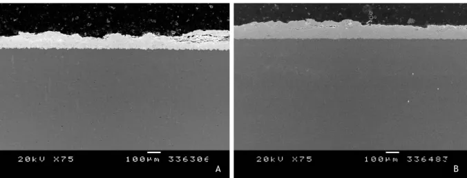
Figure 18 - Pressure field during impact (a), jetting (b). 24 Figure 19 - Multi-stage coating formation using the cold spray process. 25 Figure 20 - Previous experiments with a different WC-25Co powder. (A) 32 bar of gas pressure, 20mm of distance and 600ºC; (B) 32 bar of gas pressure, 20mm of distance and 700ºC. 29 Figure 21 - Experimental design represented by a square where each point corresponds to a
determined experiment. 30
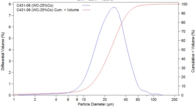
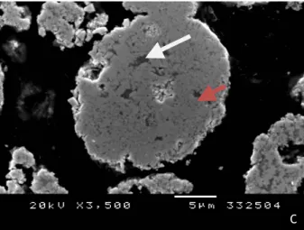
Figure 22 - Particle size distribution of the WC-25Co powder. 32 Figure 23 - (A) SEM micrograph of the free surface of the 25Co powder; (B) close-up of a WC-25Co particle; (C) close-up of a cross-sectional WC-WC-25Co particle. 333
Figure 25 - EDS analysis of the WC-25Co powder. 34 Figure 26 - Aluminium (A) and low carbon steel (B) coatings, for 40mm of nozzle-substrate spraying
distance. 35
Figure 27 - SEM micrographs of selected coatings on aluminium substrate. 36 Figure 28 - Coatings' thicknesses for each set of the aluminium substrate’s coating deposition
parameters. 37
Figure 29 - Deposition efficiencies for each of the aluminium substrate’s coating set of deposition
parameters. 38
Figure 30 - Coatings' Vickers hardness values of the aluminium substrate’s coating for each set of
parameters. 38
Figure 31 - SEM micrographs of selected coatings on low carbon steel substrate. 39 Figure 32 - Coatings' thicknesses for each set of the low carbon steel substrate’s coating deposition
parameters. 40
Figure 33 - Deposition efficiencies for each of the low carbon steel substrate’s coating set of
deposition parameters. 41
Figure 34 - Coatings' Vickers hardness values of the low carbon steel substrate’s coating for each
set of parameters. 41
Figure 35 - XRD analysis of the best set of conditions chosen for spraying onto aluminium substrate
(35bar and 20mm spraying distance). 42
Figure 36 - XRD analysis of the best set of conditions chosen for spraying onto LCS substrate (40bar
and 10mm spraying distance). 42
Figure 37 - Selected optimal experimental areas for aluminium and low carbon steel substrates. The dark balls represent the best results for each substrate. 43 Figure 38 – Binocular lens images of the samples after adhesion testing. 44
Figure 39 - EDS analysis of sample A. 45
Figure 40 - EDS analysis of sample B. 45
Figure 41 - Evolution of the friction coefficient for coatings 4 and 11, sprayed onto aluminium and
LCS substrate, respectively. 46
Figure 42 - SEM micrographs and EDS analysis of the wear tracks of coatings 4 (A) and 11 (B). 46 Figure 43 – Wear track reconstruction and profilometric analysis of coating 4 after BoD. 47 Figure 44 - Abrasive (Rubber-Wheel) wear rates versus time of coatings number 4 and 11. 48 Figure 45 - Open-circuit potential (Eoc) versus time curve for coatings 4 and 11 in aerated and
unstirred 3.5% NaCl aqueous solution. 49
Figure 46 - Photograph showing the result of 10 hours of electrochemical testing, on coating 4, and a close-up SEM micrograph of the pointed area. Notice the formation of a blue Co oxide complex. 50 Figure 47 - EDS analysis of the pointed area in Figure 46, for coating 4 after 10 hours of immersion
time. 50
Table 1 - Mechanical properties and chemical composition of the 1020 low carbon steel. 2 Table 2 - Mechanical properties comparison between two differently grain sized WC-6Co grade
cermets. 3
Table 3 - Comparison of thermal spray processes. 6
Table 4 - Typical range of gas-jet parameters for cold spray coating. 10
Table 5 - Fixed process parameters. 29
Table 6 - Factors and experimental domain. 30
Table 7 - Statistics of the particle size distribution of the WC-25Co powder. 31 Table 8 - Semi-quantitative analysis result of a cross-sectional WC-25Co powder sample. 34 Table 9 - Reference codes for the six different parameter combinations for each substrate. 36 Table 10 - Adhesion tests results for coating 4, sprayed onto aluminium substrate, and coating 11,
sprayed onto low carbon steel substrate. 44
Table 11 - Friction coefficients and volume lost after BoD test, for coatings 4 and 11. 48
ABSTRACT
This work discusses a novel deposition technique called “Cold Spraying” and focuses on the deposition of hard, wear corrosion resistant cermets, the WC-Co, on low carbon steels and aluminium substrates. Some conventional thermal deposition techniques such as Pulsed Plasma Spraying, High Velocity Oxide-Fuel and the Plasma Spraying were also discussed since these are the most widely used techniques for the deposition of hardmetals.
The WC-Co cermets have been used for applications and wear-resistant parts due to their unique combination of mechanical, physical and chemical properties. Since aluminium and low carbon steels both belong to a family of ductile materials, one could combine the properties of these with those of WC-Co to obtain both wear and corrosion/oxidation resistance applications for better performances.
Cold spray is a solid-state deposition process in which small powder particles (in the range of 5 to 50µm) are accelerated to velocities in the order of 500 to 1200m/s in a supersonic jet of compressed gas onto a substrate where the powder particles deform and bond together rapidly building up a thick layer of deposited materials. The fact that this is a solid-state process will allow for a uniform, thick, porosity and oxide free coating and usually maintaining the same properties as those of the bulk material.
1 – SUBSTRATE MATERIALS
1.1 – LOW CARBON STEELS
Low carbon steels are, of all the families of steels, those produced in the highest quantities and contain up to 0.30wt%C. This family of steels are also responsive to heat treatments and their microstructures consist of ferrite and pearlite constituents. As a consequence, these alloys are relatively soft and weak but have outstanding ductility and toughness, they’re machinable and are the less expensive to produce [1]. Typical applications include automotive body components, structural shapes such as I-beams, and sheets used in pipelines, buildings, bridges and tin cans. These applications require materials that are serviceable under a wide variety of conditions and that are especially adaptable to low-cost techniques of mass production into articles having good appearance. Therefore, these products must incorporate, in various degrees and combinations, ease of fabrication, adequate strength, excellent finishing characteristics to provide attractive appearance after fabrication, and compatibility with other materials and with various coatings and processes [1, 4]. In Table 1 some properties and chemical composition of the 0.20wt% C low-carbon steel are shown.
Table 1 - Mechanical properties and chemical composition of the 1020 low carbon steel [4]. AISI No. Tensile Strength, MPa Yield Strength, MPa Elongation, % Hardness, HV Composition, wt% 1020 448.2 330.9 36 143 0.20C 0.45Mn 1.2 – ALUMINIUM
Aluminium has an attractive combination of properties such as low density, high strength, corrosion resistance, durability, ductility conductivity and ease of fabrication making it one of the fastest growing base/alloying metals for a variety of applications. It contributes to vehicle light-weighting and subsequent energy savings, its strength and corrosion-resistance guarantee durability, and its formability allow flexibility of design and ease of handling. Aluminium is widely used in car industry, trains, ships and aerospace industry [2, 3].
2 – COMPOSITES DEPOSITION
Hardmetals, or cemented carbides, are a group of hard composites, very resistant to wear and degradation, in which hard carbide particles are “cemented” by a ductile and tough binder matrix, via liquid-phase sintering. These composite properties are achieved by combining both the toughness and plasticity of the metallic Co binder and the high hardness and strength of the covalent WC carbide. In matters of consumption and applicability the WC-Co group is regarded as the most important cermet, accounted with a quote of more than 80% in cutting applications and wear-resistant parts, especially for the heavy machinery industry [5]. The cutting tool and wear part applications arise because of their unique combination of mechanical, physical and chemical properties.
Cemented tungsten carbides are commercially one of the oldest and most successful powder metallurgy products and WC coatings have been widely used for their exceptional hardness, wear, erosion and corrosion resistance. Matrices of ductile metals, such as cobalt, greatly improve its toughness so that brittle fracture can be avoided, and even more, it allows the sintering of dense compacts at reasonable temperatures [6]. WC-Co cermets are the most important wear-resistant coating materials that are nowadays employed for deposition techniques. Their high strength (two to three times that of steel), excellent thermal conductivity, low thermal expansion, and excellent adhesion, make them the ideal coating substrate [5].
As further, these cermet properties can be controlled by composition and microstructure, in order to improve certain behaviors for specific applications. For example, the hardness of the cermet will increase with decreasing Co content and smaller particle size of WC, at some cost of rupture strength and fracture toughness [6].
Nevertheless the excellent properties mentioned in the previous paragraph there has been a reported concern on the particle size of the WC-Co powders that are used today. It is well known that nanocrystalline materials show greater mechanical properties compared to the conventional ones; the same happens when it comes to WC-Co particle size. A consequence of the smaller grain size is an improved performance, in terms of surface hardness and wear-resistance properties, as a direct consequence of the high density of grain boundaries, defects, and diffusion mechanisms that become available when a nanocrystalline size is achieved [7]. For that same reason, better coating adhesion results will be expected (this subject will be further discussed). In the following table a mechanical properties’ comparison, of a submicron and a fine/medium grain sized WC-6Co grade (%wt), is made to prove this point.
Table 2 - Mechanical properties comparison between two different grain sized WC-6Co grade cermets [5].
Grade (a) Hardness HV30 Transverse rupture strength, MPa Elastic modulus, MPa Fracture toughness, MPa.√m Thermal expansion coefficient, 10-6.K-1 WC-6Co/S* 1800 3000 630 10.8 6.2 WC-6Co/M* 1580 2000 630 9.6 5,5
(a) S*: submicron grain size; M*: fine/medium grain size.
2.1 – CONVENTIONAL THERMAL DEPOSITION TECHNIQUES
Presently there are three main deposition techniques, with its variants, of WC-Co cermet, them being Plasma Spraying, High Velocity Oxide Fuel and Cold Spraying. Limitations associated with the formation of brittle phases of the WC-Co cermet plus the decarburization observed when heated at high temperatures were the main precursor in the search and development of new and more efficient deposition processes, such as Cold Spraying.
Major commercial thermal spray process technologies can be broadly grouped into two basic categories: those that use electrical energy (Plasma Spray) and those that use chemical energy (HVOF).
2.1.1 – PLASMA SPRAY TECHNIQUES
Plasma spray is one of the mostly used electrical thermal spray processes where a partially ionized conductive gas, known as ‘plasma’, is used to melt and propel powdered feedstock material onto the substrate. To create the plasma jet, inert plasma-forming gas, usually argon or nitrogen with minor additions of helium or hydrogen is injected into the annular space between two cylindrical electrodes, and a high amperage direct current (DC) arc is then struck between the electrodes. The arc partially ionizes the gas to form a high-temperature, electrically conductive plasma, which expands and escapes through the open end of the plasma spray gun to form a very hot, high-velocity, plasma jet. This process can produce enough plasma jet temperatures to melt even the most refractory metals or ceramics. For this reason, the plasma spray process is one of the most versatile of all spray processes, able to deposit an exceptionally wide range of materials. There are two main Plasma Spray processes: Conventional Plasma (APS) and Vacuum Plasma (VPS) [8].
The conventional process ought to be the Atmospheric Plasma Spray for its relative lower cost when compared to the Vacuum Plasma Spray process. The main advantages of the Plasma Spray processes is the capacity to achieve plasma temperatures ranging from 6000 to 15000ºC, values above the melting point of every known material, and effectively deposit a wide range of materials. The Vacuum Plasma, or Low-Pressure Plasma, Spray uses low-pressures in the range of 0.01 to 0.05MPa) inside the chamber before ionizing the gas. Afterwards, and considering the pressure is very low, the plasma becomes larger in diameter and length and will be forced through a converting/diverging nozzle, resulting in a higher gas speed than those achieved with the APS process. In order to constantly maintain the working chamber pressure, efficient pump systems have to be employed to remove the injected plasma gases. The main advantages of this process, when compared to the previously mentioned ones, would be the ability to produce denser, more adherent coatings with much lower oxide contents (due to the lack of oxygen inside the chamber) [8]. Another advantage of the VPS technology is the option to clean the substrate surface especially from oxide layers and preheat the substrate, both giving better adhesion [9]. The better adhesion results can also be explained by the higher substrate temperatures since the cooling and convective heat transfer inside the chamber are reduced, therefore improving diffusion and reducing cooling residual tensions. On the other hand there are usually high investments and maintenance costs for achieving the vacuum conditions [9].
Figure 1 - Schematic diagram of the plasma spray process [10].
The Pulsed Plasma Spray technique is a novel thermal spraying-based process that through the action of a repetitively pulsed plasma jet, generated by an arc discharge, will simultaneously melt and accelerate (into the 2000m/s to 4000m/s range) the coating material’s powder particles. Such conditions, ideal for the melting and acceleration of the particles, are achieved due to the capillary arc discharges, which will readily produce states of high pressure, high temperature and high velocity gas (that being plasma) [11]. The operational process of this technique is illustrated in Figure 2.
Figure 2 - Operational sequence of a Pulsed Plasma Spray [11].
Firstly, there will be a chemical energy input, in the form of a short duration high-power electrical-arc discharge that will heat a working fluid/gas at pressures of over 100MPa and temperatures above 11000ºC. Consequently the high velocity plasma will tend to rapidly expand down the direction of the barrel’s exit, entrain and heat the previously injected powder suspension, and thus accelerating and spraying it onto a substrate [9, 11]. The incorporation of an inert gas (He or N2) will prevent any kind of chemical reaction of
the particles with the air prior to impact [11]. With this novel process, high velocities are accomplished – WC-Co powders were accelerated to velocities ranging from 1500 to 2200m/s – without using combustible gases and a vacuum chamber, maintaining at the same time an inert atmosphere for the particles during the spraying stage [11].
Automatically any kind of costs related to maintaining the vacuum conditions inside the chamber would be minimized.
In the following table are indicated and compared some of the systems parameters concerning the discussed Thermal Spray techniques.
Table 3 - Comparison of thermal spray processes [8].
Process Flame or exit plasma temperature (ºC) Particle impact velocity (m/s) Relative adhesive strength (a) Oxide content (%) Relative process costs (a) APS 5500 240 6 0,5-1 5 VPS 8300 240-610 9 ppm values 10 PPS[7] 11000 2000-4000 9 ppm values 5 HVOF 3100 610-1060 8 0,2 5
(a) low (1) to high (10)
2.1.2 – HIGH VELOCITY OXYGEN FUEL
The High Velocity Oxygen Fuel, commonly known as HVOF, is one of the most versatile conventional chemical thermal spray deposition techniques. In this process an explosive high-volume mixture of gases (hydrogen, propylene, propane, acetylene and kerosene), oxygen and powder (borne by a carrier gas and fed into the nozzle), is fed into a combustion chamber. A spark plug will then generate combustion at very high combustion chamber pressures exceeding 241 kPa and heat inputs of nominally 527 MJ; the resulting heated gas will exit through a converging-diverging nozzle therefore generating a supersonic gas jet (check point 4 for a deeper insight on the de Laval nozzle) - the sheer volume of gas flow, coupled with the high temperature of combustion, creates gas velocities in the range of 1525 to 1825 m/s [9, 13]. As the exiting gas jet expands through the nozzle and achieves supersonic velocities it will cool as thermal energy is converted to kinetic energy; the high pressure and velocity wave will heat and accelerate the powder particles – in this stage velocities of the order of 450-1000m/s are achieved - forcing them to travel down the barrel toward the substrate [12]. Depending on the process parameters such as the spray device, spray material and operating conditions different particle velocities and adhesion efficiencies are obtained.
Figure 3 - Schematic diagram of a HVOF spray gun [8].
The high gas velocity generated by HVOF will increase particle velocity, with a corresponding increase in coating density and adhesion with very little porosity (between 0.5 and 1.0%) and also create a more favorable compressive stress state caused by the peening effect of these high-velocity particles impacting the substrate’s surface. Lower average particle temperatures, compared to plasma spray, reduce the degree of particle melting and oxidation [9, 13].
The lower jet temperatures and higher particle velocities of HVOF make it a preferred process for applications such as spraying dense cemented carbide wear-resistant coatings, where the lower process temperatures prevent decarburization and the high impact velocities produce a relatively pore-free coating with a favorable residual stress state that makes it less prone to cracking.
2.2 – ADVANTAGES
The principal advantage of the conventional thermal spray deposition processes is the ability to deposit a wide range of materials that have a stable molten phase. Even some materials that do not melt can be co-deposited with another sprayable material thus creating a composite material coating – this is another advantage of these processes. Besides being able to deposit a wide range of materials it is also possible to deposit on an even wider range of substrates, even to temperature-sensitive materials because the thermal energy in a single droplet of molten spray material is quite limited therefore avoiding excessive heat build-up in the substrate. Some particle heating occurs on impact from the conversion of kinetic energy into thermal energy, which further aids in producing dense coatings. This process also offers the possibility to rapidly and economically coat very large surfaces meaning that it offers very high deposition rates (the material is deposited as 10-100µm molten droplets) [12].
The process’s effluents are relatively easy to control and dispose of in an environmentally friendly manner.
2.3 - LIMITATIONS
The presence of porosity is one of the greatest limitations of traditional thermal spray processes because it can dramatically affect the coating’s mechanical properties and if intended to protect the underlying substrate material from exposure to liquid or gaseous species that may cause corrosion and other problems. Porosity values vary according to the specific spray process, material and deposition conditions. Usually, higher velocity processes can produce coatings with less porosity, typically of the order of 3-8%vol. [12].
Another drawback associated with this family of processes would be the undesirable presence of oxides in the spray-deposited material, meaning that the use of oxygen in this process requires special protection measures. These defects and impurities in the sprayed material’s microstructure can degrade the mechanical, electrical and thermal properties of the coating as compared with the same material in conventionally processed form. Also, as these require heating to allow deposition of the powder particles it can result in the vaporization of more volatile species in a complex metal alloy causing a change in the chemical composition of the deposited material. Processes such as HVOF, that minimize heating of the spraying material result in lower oxide concentrations and minimal changes in alloy chemistry [12].
Residual stress is also a limitation of most thermal spray processes. The residual tensile stresses appear whenever each molten droplet solidifies and then cools to room temperature, undergoing in thermal contraction in direct proportion to the temperature change and the thermal coefficient of expansion for that material. Every time a new layer of coating material is deposited, the underlying and already solidified material, which is at a lower temperature, will result in a state of residual tensile stress, increasing as subsequent layers of material are added. Additionally, the steadily increasing residual tensile stress will limit the maximum thickness of thermal spray coatings and can sometimes crack or separate the coating from the substrate material. Coatings sprayed by HVOF processes, which tend to have less residual tensile stress because of the peening effect of the high-velocity impacting powder particles, may be in a state of compressive residual stress therefore superposing coating cracking and separating problems [12].
In virtually all thermal spray processes the deposition is limited to surfaces that are directly accessible to the spray stream.
3 – THE COLD SPRAY PROCESS
The cold spray process as a deposition technology was developed by a group of Russian scientists of the Russian Academy of Science in the mid-80s. This group, led by
Professor Anatolii Papyrin, could deposit a wide variety of materials such as pure metals, metallic alloys, polymers and composites onto various substrate materials obtaining very high coating deposition rates using this novel deposition process. While studying models subjected to a supersonic two-phase flow (gas + particles) in a wind tunnel it was verified that it would be possible to deposit a wide range of materials on various substrates without the use of temperature to melt and deposit the spraying materials, as it was usually done on the most common thermal deposition processes [12].
Unlike the conventional deposition techniques, which require both kinetic (particle velocity) and thermal (temperature) energy in order to promote coating formation onto a substrate, the cold spray process simply uses the kinetic energy of the powder particles for the coating formation. The kinetic energy of the impinging particles is sufficient to produce plastic deformation and high interfacial pressures and temperatures meaning it is, almost entirely, a solid-state process. Furthermore, because cold spray is a low-temperature process, i.e., does not use thermal energy, it produces less porous coatings with less oxidation and higher hardness.
Figure 4 - Schematic diagram of the cold spray process [12].
In the cold spray process it is necessary to produce a high-velocity stream of gas in order to give the powder particles enough kinetic energy to allow deposition onto the substrate. The metal powder particles which range in particle size from 5 to 50µm are fed centrally, by a separate gas stream typically introduced into the high-pressure side of a de Laval converging-diverging nozzle (Figure 5) where a preheated gas (usually air, He, N2, or
mixture depending on the deposition material and gas temperature) in the range of 300-800ºC is compressed and will expand to supersonic velocity while decreasing in pressure and temperature. Such velocities can be reached due to the changes of geometry and Mach ( , where s is the gas exit speed and is the speed of the sound in the medium)
gas is compressed, representing a subsonic Mach velocity (M < 1); at the throat, where the cross sectional area is minimum, the gas velocity becomes transonic (M = 1) and as the nozzle’s cross sectional area increases the gas expands and its flow reaches supersonic velocities (M > 1) [13]. This can be seen on the depicted diagram in Figure 5. It has to be noted that the gas is heated not to heat or soften spray particles, but instead to achieve higher sonic flow velocities, which ultimately result in higher particle impact velocities.
Since the contact time of the injected particles with the hot gas is short and the gas cools as it expands, it is considered that the particles temperature remains below its melting temperature. The term “cold spray” has been used to describe this process due to the gas stream’s exiting temperature (-100 to 100ºC) [12, 14].
Table 4 - Typical range of gas-jet parameters for cold spray coating [8].
Gas-jet parameters for cold spraying
Stagnation jet pressure (MPa) 1-3
Stagnation jet temperature (ºC) 0-700
Gas flow rate (m3/min) 1-2
Powder feed rate (kg/h) 2-8
Spray distance (mm) 10-50
Power consumption (kW) 5-25
Particle size (µm) 5-50
Operating gases: air, nitrogen, helium, and their mixtures
There are several parameters that can influence the quality of the deposition (will be discussed further in this paper) being the critical velocity the most important one. The critical velocity is the minimum value of velocity that an individual particle must attain in order to deposit after impact with the substrate; if a particle fails to attain such velocity then it will bounce off the surface and erode it. In the cold spray process the particles are accelerated to velocities in the range of 500-1200m/s, and if enough to achieve a critical velocity the solid particles will plastically deform and flow out upon impact, creating hydrodynamic flow instability at the interface between the incoming particle and the substrate, resulting in bonding [12].
Figure 5 - Diagram of a de Laval nozzle showing approximate flow velocity (v), together with the effect on
temperature (T) and pressure (P) [15].
3.1 – ADVANTAGES
Since cold spray is a solid-state process and does not require high temperatures to promote adhesion between the coating and the substrate material there are a large number of advantages associated with this process when compared to conventional thermal spray processes. This can be a very important advantage if a low porosity and low oxide content coating is desired. As so, these are two of the greatest advantages when producing coatings with cold spray: low porosity and low oxide content. Low porosity results from the fact that cold spray is, as stated before, a solid-state process so there is no melt and splashing of the powder particles onto the substrate; in addition, there will be a peening effect resulting from the impact of particles present in the outer high-velocity jet stream which tend to close any small pores and gaps in the underlying coating material which will also result in a very high density. As for oxidation of the metal powder during deposition, since it is processed at low temperatures, any reactions of metals with oxygen is greatly reduced or eliminated. Moreover, as these two “defects” are reduced there will be an improvement of mechanical, electrical and thermal properties. In cold spray it is possible to obtain ductile coatings, after performing a post-deposition heat treatment to anneal it, since they’re oxide and porosity free [12].
In cold spray chemistry, phase composition and crystal (grain) structure of the feedstock powder are preserved in the final coating; this means that the initial particle material’s properties are retained and the final product will show the exact same properties as the one’s evidenced by the bulk material’s powder. Low temperature is once again the main precursor of these advantages because it prevents vaporization of more volatile elements in the deposition process (maintaining the powder’s chemistry), also the melting and solidification processes are inhibited so the phase composition and crystal structure remain unaltered. This can be an amazing advantage if someone wishes to work with nanocrystalline powders since their unique properties won’t be changed by thermal grain growth [12].
High density, phase purity and homogeneous microstructure of cold spray coatings also promote exceptional corrosion characteristics.
Since the cold spray particles are deposited at relatively low temperatures there is little temperature-drive dimensional change (thermal contraction). Adding the peening effect to this results that cold spray coatings are typically in a state of compressive residual stress that will prevent cracking and coating separation. This can also be a plus as thicker coatings can be obtained in this state of favourable residual stress. This process also shows very high bond strength over many substrates (metals, alloys, composites, etc.), even more it is possible to work with highly dissimilar materials since cold spray does not heat and melt the coating material and the formation of weak interfaces is avoided. Furthermore, in this process, there is a minimum thermal input to the substrate (the one received by the enthalpy of the impacting particles), which allows working on substrates made of temperature-sensitive materials [12].
It is also possible to deposit coating materials in highly localized areas without the need for costly masking operations. Moreover, this process has an elevated deposition rate due to its narrow and well-defined spray beam.
Considering all the previous advantages and high feeding powder rates it is also expected high deposition efficiency (DE) values for most materials.
The absence of high-temperature gas jets, radiation and explosive gases will increase operational safety.
Figure 6 - Comparison of process temperature and particle velocity ranges for several common thermal spray
processes and cold spray [12].
3.2 – LIMITATIONS
The cold spray process, unlike traditional thermal spray processes, is essentially limited to depositing materials that exhibit good ductility to produce quality bonds between the coating and the substrate material. The fact that it is a solid-state process and the powder particles do not melt before impact, these should have at least a limited
ductility in order to deform and create the hydrodynamic shear instability that bonds the particles with the underlying material. At the same time, the substrate material should be hard enough to allow the ductile particles to deform upon impact. So, in cold spray, harder and more brittle materials can’t be used as coating material, and softer materials can’t be used as substrates; although this is very limitative, composites that have a ductile matrix such as WC-Co can be deposited. Furthermore, this extensive plastic deformation suffered by the particles impinging on the substrate will provide a work hardening effect on the coating and result in very low ductility in the as-sprayed condition – for some applications it can be an issue while in other, such as wear resistant components, it can be an advantage [12].
Another drawback of cold spray is that it consumes much more process gas than the traditional thermal deposition techniques, in the order of 1-2m3/min. If to this we add that some deposition materials such as titanium, which have high individual particle critical velocity, require the use of very expensive gases (He) to achieve the necessary impact velocity and coating quality then it can turn into a costly process and become a huge drawback [12]. A solution could be using higher pre-heating temperatures (~800ºC) of the nitrogen in order to achieve superior existing jet velocities hence providing the minimal velocity ( c) for deposition materials that require higher values of critical velocity.
Since the cold spray process’s gun produces a very thin and well-defined beam it makes the process not suitable for coating very large surface areas. As in other processes, this is also a line-of-sight process hence spraying complex shapes and internal surfaces is difficult [12].
Although cold spray offers a wide range of advantages, such as low level of porosity and oxidation, it won’t replace the traditional thermal spray processes mainly due to its limitation in coating/substrate materials compatibility.
3.3 – PROCESS PARAMETERS
The cold spray process will be influenced by several parameters (critical velocity; particle, gas and substrate temperature; powder size; etc.). Controlling these parameters will allow understanding the nature of the cold spray phenomenon and control the basic coating properties. One of the most important characteristics of the process is the deposition efficiency, which is defined as the ratio of the mass gain of the substrate during its exposure to the flow with the proper set of parameters and the decrease/consume in powder mass in the feeder during the same time [16]. The relative deposition efficiency, RDE, is used to estimate the weight gains of coatings of several samples, through measuring its weights before and after deposition.
Figure 7 – Relative deposition efficiency, where Wc is the coating weight at a certain standoff distance and
Wcmax is the maximum weight among the coatings deposited at different standoff distances [17].
3.3.1 – PARTICLE VELOCITY
The particle velocity prior to impact is one of the most important parameters in the cold spray process. There is a critical velocity value that depends both on particle and substrate nature and properties, below which no particle adhesion to the surface is possible. Particles hitting the substrate will either adhere (by plastic deformation) to it or bounce back (and erode the substrate surface). Optimizing this parameter will reduce the manufacturing costs by increasing the deposition efficiency. For a given material, there exists a critical velocity resulting in a transition from erosion of the substrate to deposition of the particle. Only those particles achieving a velocity higher than the critical one can be deposited to produce a coating.
It is important to have a narrow distribution window of particle size due to the effects of erosion/adhesion. As explained before, when a particle (usually the larger ones within a distribution window) does not achieve its critical velocity it will hit the surface of the substrate and bounce back eroding it hence reducing the deposition efficiency of the process. The velocity distribution was combined with the measured deposition efficiency and the particle size distribution, to give the size and velocity of the largest particle that would bond successfully to the substrate [12, 18-22]. Erosion can also appear when the particle velocity is too high thus exceeding the deposition efficiency saturation point and causing a large-impact dynamics phenomenon. Brittle materials would cause erosion for any velocity at temperatures below their melting point. This is depicted on Figure 8.
Figure 8 - "Window of deposition" depicting a correlation between particle velocity and deposition efficiency
for a constant impact temperature [20].
As particle velocity is higher than the critical one, the deposition efficiency increases with increasing the impact velocity. A further increase of velocity leads to an increase in deposition efficiency until it reaches the saturation level of almost 100% deposition efficiency. After reaching this limit the deposition efficiency will decrease with an increase in particle velocity due to the phenomenon discussed before. At the velocity where deposition efficiency is 0%, erosion velocity is defined – being usually two to three times higher than critical velocity [12, 20].
Based on an analysis and correlation of material properties and the critical velocity – or an interplay between kinetic energy, material strength and heat generation due to plastic deformation - Schmidt et al. [20] defined that critical velocity could be as:
Figure 9 - Critical velocity, where σ is the temperature-dependent flow stress, ρ is the density, Cp is the heat
capacity, Tm is the melting temperature, T is the mean temperature of particles upon impact, and A and B are fitting constants [20].
Moreover, the particle velocity increases with the decrease of particle size and a higher velocity can be obtained for a particle of lower density under the same gas conditions, or by incorporation of the materials into a ductile matrix (cermets, for example) [12].
3.3.2 – PARTICLE, GAS AND SUBSTRATE TEMPERATURE
Particle velocity is influenced by several parameters being the particle, gas and substrate temperature three of the most important; so, controlling the temperature of
these parameters will allow for a greater deposition efficiency of the process. Thus, the coating quality can be further improved by increasing the initial temperatures of the particles and substrates.
If one wants to increase particle velocity increasing the gas temperature will result in higher particle velocities and lower critical velocity values. Generally, the purpose of increasing the gas temperature is not to heat the particles temperature but rather to increase the gas velocity. Also, using a smaller molecular weight gas such as helium will provide higher gas velocities as it is stated by the equation:
Figure 10 - Equation for the speed of sound, where γ is the ratio of specific heats (1.4 for air, 1.66 for He), R is
the gas constant, T is the gas temperature, and Mw is the molecular weight of the gas [12].
Altering the particle and substrate temperature will affect the physical and mechanical properties of the particle at the substrate in a way that will generally result in a reduced mechanical performance. Since particles at higher temperature need less kinetic energy to heat particle surface areas by plastic deformation, increasing the particle temperature should allow one to decrease the particle velocity necessary to achieve the same deposition efficiency for the coating. Additionally an increase in particle temperature improves the particle-particle adhesion. Moreover, heat conduction will be less effective due to lower temperature gradients, which leave more time for diffusion and bonding [12, 22]. Figure 11 shows how critical velocity varies with temperature.
3.3.3 – POWDER SIZE, MORPHOLOGY AND DENSITY
Using materials with a finer grain structure will imply an increased amount of grain boundaries thus impeding dislocation motion and improving properties like hardness, toughness and even sliding and abrasion resistance. When compared to conventional materials, nanocrystalline materials are typically characterized by a significant increase of mechanical properties. For these reasons, the use of nanostructured feedstocks can produce these improvements in microstructure and bonding of the final coating [23].
For materials with a smaller particle size distribution a higher particle velocity is expected. This is due to the fact that the gas/particle momentum transfer or particle acceleration imparted by the gas is proportional to 1/d, based on Newton’s law (acceleration and deceleration of the particles are considered to be action of the drag force acting on a particle which is proportional to the particle drag coefficient; an increasing drag coefficient leads to an increased drag force acting on the particle and thus to a higher particle velocity). Consequently, a smaller particle size will result in higher acceleration and particle impact velocity [24]. This means that a lower gas/particle temperature is needed, avoiding possible effects of oxidation of the small grain sized powder particles, resulting in better coating quality and characteristics.
Since one is relying on the coupling of the high-velocity gas stream to accelerate the particles, the particle morphology will determine the deposition efficiency. Long aspect shapes do not present a large cross-sectional area to promote drag effects. This type of particle geometry will tend to orientate into a direction that will present a reduced cross-section perpendicular to the gas flow reducing the drag coupling and consequently the final particle velocity.
The particle density is another factor to consider. Particles with a high density, such as tungsten, will accelerate more slowly than particles with a lower density such as aluminum. The very-high-density materials may also require higher velocity powder carrier gas flows, such as those provided by helium, to maintain particle suspension in the gas flow for the journey to the nozzle [12].
3.3.4 – POWDER FEEDING RATE
Loading of the powder particles can also influence the properties of the coating. Varying the mass flow rate at which the powder particles are fed into the carrier gas stream can affect the coating’s thickness.
Excessive powder feeding rate may saturate the gas stream flow resulting in a reduction in particle impact velocity due to a reduced gas/particle momentum transfer, while insufficient particle mass flow rate may lead to reduced coating thickness or
coatings with high porosity. Increasing the powder feed rate increases the coating’s thickness linearly until a maximum powder feed rate is reached for which there are too many particles impacting the surface of the substrate resulting in excessive residual stress causing the coating to peel - as a result of the higher powder mass flow rate, too many particles impact the substrate over a given surface area per unit time resulting in an increase in residual stresses in the coating (shot peening effect) [25].
Figure 12 - Example of a chart depicting the coating thickness as a function of the powder mass flow rate for
copper [25].
3.3.5 – SPRAYING ANGLE
The deposition efficiency will also be affected by the spray angle and, since the particles deformation depends mainly on its, velocity this variable is considered to influence the coating characteristics and deposition behaviour.
The particle impact velocity is decomposed into a normal and a tangential velocity component, relative to the substrate surface:
Supposing that the tangential velocity component is negligible, the deposition efficiency will be solely affected by the normal velocity component. When particles are sprayed at an
Figure 14 - Decomposition of particle impact velocity at spray
angle of θ [26].
Figure 13 - Normal and tangential velocity
component, here Vp is the particle impact velocity, Vn the normal component and Vt the tangential component of Vp, θ the spray angle between the nozzle and the substrate [26].
off-normal angle relative to the substrate surface, the normal component of the particle velocity will be inferior compared with that at the normal angle. With the decrease in the spray angle, the normal component of the velocity will be decreased until a point where its velocity is below the critical velocity thus not being able to deposit on the substrate. Also the flow direction of the depositing particles, which usually deposit perpendicular to the particles approaching direction, will be altered hence significantly influencing the layering directions of the spray particles and the coating’s microstructure [25, 26].
Figure 15 - Dependency of relative deposition efficiency on spray angle [26].
As it can be observed in Figure 15 there exists three typical angle ranges: maximum deposition angle range, transient region angle range (both depend on the particle mean velocity and velocity distribution) and no deposition angle range. At the maximum deposition angle range – this being 90º - the relative deposition efficiency reaches 100%; the angle range in which the relative deposition efficiency decreases from 100% to zero is defined as the transient angle range, being quite broad for the particles presenting a wider velocity distribution and narrower for the smaller ones [25, 26].
3.3.6 – NOZZLE-SUBSTRASTE STANDOFF DISTANCE
The nozzle-substrate standoff distance is also one of the most important parameters in the cold spray deposition process. It is known that at short standoff distances the impact velocity of small particles is reduced as a consequence of the bow shock formed at the substrate hence affecting the deposition efficiency of the process. The bow shock (Figure 16) is defined as a shockwave occurring as a result of a supersonic flow on the substrate; as gas molecules in the primary jet-flow impact with the substrate there is a general change in molecular energy which is transmitted to other regions of the flow by pressure waves travelling at the speed of sound thus forming a normal shockwave. The bow shock will enclose a region of high-density, low-velocity fluid that will affect the
velocity and trajectory of the incoming primary jet’s particles. As across the bow shock and the stagnation bubble there will be some negative drag forces decelerating the particles the deposition efficiency will be reduced if their velocity falls below the critical velocity; not only the bow shock will prevent the small momentum and sized particles to maintain their velocity to the substrate, but also larger particles with velocities only slightly above theirs critical velocity value [27].
Figure 16 - Schematic diagram of the supersonic impingement zone at the substrate [27].
Therefore in order to achieve optimum performance this parameter should be controlled, using diagrams such as the one depicted in Figure 17, where three distinct regions can be seen. At the first region, where the standoff distance is smaller, the presence of the bow shock adversely affects deposition performance, and is limited by the length of the nozzle's supersonic potential core; at the medium standoff region, where the bow shock has disappeared and, if the gas velocity remains above the particle velocity (positive drag force), the deposition efficiency continues to increase until 100%; and at the large standoff region, where the gas velocity has fallen below the particle velocity (negative drag force), and the particles begin to decelerate hence decreasing the deposition efficiency as the standoff distance is increased. For optimal deposition the standoff distance should be set within Region 2 [27].
Figure 17 - The effect of standoff distance on deposition efficiency. Here Fd is the drag force, Mc is the
centreline Mach number, Vg is the gas velocity, Vi is the particle impact velocity and Vp is the in-flight particle velocity [27].
Besides the decrease of the deposition efficiency with the standoff distance, also the coating thickness decreases with the standoff’s distance increase [17].
In cold spray the selection of a too short standoff distance could compromise the coating’s oxide content because at shorter distances the previously deposited coating/substrate will be exposed to a higher gas temperature. Therefore, the selection of standoff distance should be careful with compromising the deposition efficiency and possible oxidation for temperature susceptive materials [17].
3.3.7 – SUBSTRATE ROUGHNESS AND THICKNESS
Studies show that the use of different grit sizes leads to changes in the mass deposited on the substrate (deposition efficiency) but have no significant effect on the coating microstructure. Both substrate preparation and substrate thickness showed to have effect on the final coating’s characteristics hence making them cold spray process parameters. Since one of the suggested bonding mechanisms is associated to mechanical interlocking (check section 3.4) it is possible to assume that an increased substrate roughness would further enhance bonding as it presents a greater array of recesses in which the particles can be lodged and then be subjected to additional compaction as successive particles impact on the substrate. Larger recesses also allow larger particles to come into better contact with the substrate. For surfaces with low roughness, the first particles to impact have fewer chances to bond because they have little surface area with which to bond, resulting in weaker bond strengths. All considered, a larger surface roughness area appears to be beneficial for the deposition efficiency of the process, although affecting it only for the first few layers of particles impinging on the substrate. A thinner substrate won’t affect negatively the deposition efficiency or resulting microstructure meaning that this process can also be used for very thin substrates [28].
3.4 – BONDING MECHANISM
In the cold spray process, bonding of the coating to the substrate occurs when the impact velocity of the powder particles equals or exceeds its critical velocity value, happening a localized deformation and adiabatic shear instability at the same time. The adhesion of the particles to the substrate in this process is due solely to their kinetic energy upon impact even though the actual mechanism by which the solid particles deform and bond during cold spray is still not well understood [12]. During cold spray deposition there are two very different stages. During the initial stage, a thin film of particle material (monolayer) is deposited on the substrate. This stage is characterized by a direct interaction of particles with the substrate and depends very much on the degree of surface preparation and on the properties of the substrate material. The initial stage includes the time of surface activation, i.e., the incubation time, during which erosion instead of deposition can occur. In the second stage a coating layer of finite thickness is build up. In this stage particles interact with a surface formed by particles themselves [29].
It is know that the substrate, or the deposited material (depending if it has already been deposited a layer of coating material), and the powder particles undergo an extensive localized deformation during impact therefore providing the necessary conditions for particle/substrate and particle/deposited material bonding, by means of a clean contact surface and high pressures. Localized deformation is known to cause disruption of the thin oxide films (as oxides tend to be more brittle than metals fracturing these oxide shells becomes a necessary part of coating formation) on the surface and enabling an intimate contact between the particles and the substrate/deposited material. This hypothesis is supported by such findings: (1) a wide range of ductile materials can be cold sprayed while non-ductile materials can be deposited only if they are co-cold sprayed with a ductile (matrix) material – plastic and localized deformation; (2) the mean deposition particle velocity should exceed a minimum critical velocity value to achieve deposition, which suggests that sufficient kinetic energy must be available – plastic deformation/disruption and cleaning of the surface films [12].
Moreover there are a number of phenomena that are frequently responsible for inter-phase bonding such as interfacial melting, atomic inter-diffusion and plastic deformation which are now believed not to play a significant role in the bonding mechanism of cold spray. This conclusion was elaborated based on the following [12]:
- The average kinetic energy of the particles is significantly lower than the energy required to melt the particle/substrate interfacial region meaning that the particle/substrate bonding is a solid-state process;
- Provided very short particle/substrate contact times, atomic inter-diffusion is not expected to play a significant role in particle/substrate bonding. This can be readily proven as follows: the metal-to-metal inter-diffusion coefficient at temperatures near the melting point is of the order of 10−15 to 10−13 m2/s, and
for a typical particle/substrate contact time of 40 ns, the atomic inter-diffusion distance is between 0.004 and 0.1 nm. Since this distance is only a fraction of the inter-atomic distance, atomic diffusion at the particle/substrate interface should be excluded as a dominant particle/substrate bonding mechanism under the dynamic cold-spray deposition conditions.
So it is possible to conclude that the temperatures that are achieved in the interfacial region will be neither enough to produce interfacial melting nor to significantly promote atomic inter-diffusion, plus, adhesion is an atomic length-scale phenomenon and its occurrence is controlled by the presence of clean surfaces and high contact pressures [12].
As mentioned before, in order for efficient adhesion to take place at the particle/substrate contact surfaces, such surfaces must be clean and subjected to high contact pressure plus, and all of the particle’s kinetic energy must be transformed into heat and strain energy to the coating and substrate. A phenomenon known as adiabatic shear instability and the localization of the plastic flow into interfacial jets will ensure cleanliness of the surfaces during cold spray; thus high particle velocities will ensure the necessary high levels of particle/substrate contact pressure. At the highly strained interfaces, oxide shells are broken and the heated surfaces are pressed together and are thus bonded. In cold spraying, in particular, ductility is needed to obtain sufficient flattening of particles in order to build up a dense coating [22]. This and the resultant plastic-flow localization are the phenomena that are believed to play a major role in the particle/substrate bonding during cold spraying.
Adiabatic shearing, occurring at strain-rates above 103 s-1, is expressed as a much
critical thermo-plastic material instability, i.e., by the balance between only the two strain-rate hardening and thermal softening terms. This meaning that, under adiabatic conditions, the plastic strain energy dissipated as heat increases the temperature causing thermal material softening and consequently decreasing the rate of strain hardening [30, 31]. It has also been suggested that the dissipation of kinetic energy into heat is strain rate
dependent, i.e., the fraction of plastic work dissipated into heat would be larger for higher strain rates. This would further support the assumption of adiabatic heating in cold gas sprayed particles [30].
Figure 18 - Pressure field during impact (a), jetting (b) [22].
When a particle first impacts, a strong pressure field propagates spherically - Figure 18 (a) – into the particle and the substrate from the point of first contact. This is followed by generation of a shear load, due to a pressure gradient at the gap between the colliding interfaces, accelerating the material laterally and thereby causing localized shear straining. Adiabatic shear instabilities phenomenon will appear when the impact pressure and the respective deformation are high enough thus occurring thermal softening of the material meaning that the latter process is locally dominant over strain and strain-hardening, which leads to a discontinuous jump in strain and temperature and consequently an immediate breakdown of stress. Also, in this region, the viscous flow will generate an out-flowing material jet with material temperatures close to the melting temperature – Figure 18 (b) [22]. The coating build-up is not a simple one-particle impact, but rather a series of multiple impacts that transfer the incoming particle’s kinetic energy to the substrate initially and then to the coating. A multistep process has been suggested consisting of substrate cratering and first-layer build-up, followed by particle deformation and realignment, metallurgical bonding and void reduction (Figure 19). When the deposition process is about to end it should be expected to have a not as well compacted last layer of coating as the first and medium ones, since the last particles that arrive and conform the last layer will not be impacted by any other particles and be subjected to the previously discussed mechanisms.
It is also suggested that an interfacial instability-based mechanism, by which interfacial mixing/interlocking occur, may also contribute to particle/substrate bonding. Interfacial instability can arise when two fluids are moving at different velocities in a direction parallel to their interface. When an interface is subjected to a perturbation, then as one fluid flows around the other a centrifugal force is generated thus raising a
change in pressure, which may promote amplification of the interfacial perturbations. These instabilities may then lead to the formation of interfacial roll-ups and vortices which may enhance the overall strength of interfacial bonding in at least three ways: (1) by significantly increasing the interfacial area available for adhesion; (2) by producing a fine length-scale mixing of the two materials; (3) by creating mechanical interlocking between the two materials. Also a particle length-scale, rivet-like mechanism may also be operative and its onset may be linked with the minimum critical particle velocity [12, 30, 32].
Figure 19 - Multi-stage coating formation using the cold spray process [12].
4 – EXPERIMENTAL PROCEDURE
In order to study and characterize the cold spray’s obtained coatings some tests must be carried out according to the specified ASTM standards so these results can be later compared with those obtained, and extensively published, by the characterization and study of HVOF coatings. It is a very important step of the work in progress because it will allow determining if the chosen process parameters were the most effective and then optimizing them, also it will provide the knowledge to understand if this process brings in fact more advantages and efficiency when compared to other conventional thermal spray techniques. It is the intent of these test methods to produce data that will reproducibly rank materials in their resistance under a specified set of conditions.
A structural characterization of the feedstock powders will be performed as well as adhesion, wear and corrosion tests.
4.1 – STRUCTURAL CHARACTERIZATION
Prior to characterization, the substrates and resulting coatings shall be cut on the transverse to view cross sections using a diamond saw. Secondly, they must be subjected
![Table 2 - Mechanical properties comparison between two different grain sized WC-6Co grade cermets [5]](https://thumb-eu.123doks.com/thumbv2/123dok_br/15195897.1017412/14.892.129.772.615.776/table-mechanical-properties-comparison-different-grain-sized-cermets.webp)
![Table 4 - Typical range of gas-jet parameters for cold spray coating [8].](https://thumb-eu.123doks.com/thumbv2/123dok_br/15195897.1017412/21.892.126.821.465.683/table-typical-range-gas-parameters-cold-spray-coating.webp)
![Figure 8 - "Window of deposition" depicting a correlation between particle velocity and deposition efficiency for a constant impact temperature [20]](https://thumb-eu.123doks.com/thumbv2/123dok_br/15195897.1017412/26.892.262.631.123.369/deposition-depicting-correlation-particle-velocity-deposition-efficiency-temperature.webp)
![Figure 10 - Equation for the speed of sound, where γ is the ratio of specific heats (1.4 for air, 1.66 for He), R is the gas constant, T is the gas temperature, and M w is the molecular weight of the gas [12]](https://thumb-eu.123doks.com/thumbv2/123dok_br/15195897.1017412/27.892.240.654.808.1048/figure-equation-speed-specific-constant-temperature-molecular-weight.webp)
![Figure 12 - Example of a chart depicting the coating thickness as a function of the powder mass flow rate for copper [25]](https://thumb-eu.123doks.com/thumbv2/123dok_br/15195897.1017412/29.892.277.622.333.596/figure-example-depicting-coating-thickness-function-powder-copper.webp)
![Figure 19 - Multi-stage coating formation using the cold spray process [12].](https://thumb-eu.123doks.com/thumbv2/123dok_br/15195897.1017412/36.892.297.580.367.631/figure-multi-stage-coating-formation-using-spray-process.webp)